


Description
Coherent CBPDV2120R Balanced Photodetector 43 GHz, C-Band 1525-1575 nm, FC/PC
Coherent CBPDV2120R is a 43 GHz balanced photodetector integrating two waveguide-structure photodiodes on a single chip, with a 3 dB cutoff of 42 GHz (C-band specification value) and an optical window of 1525–1575 nm (typ. 1550 nm). The bias network is integrated on-chip, keeping the response undistorted from DC to the 3 dB cutoff with no external bias tee; responsivity ≥0.4 A/W (best polarisation, typ. >0.5 A/W), polarisation-dependent loss PDL ≤0.4 dB, and linear response up to 10 dBm average optical input power. V® (1.85 mm) RF connector — female or male optional — plus an FC/PC (standard) or FC/APC fibre interface. Suited to 43 Gb/s coherent communications, microwave photonics, analogue optical links and high-speed test & measurement. The tax-inclusive price is shown in the price box on this page (13% VAT included).
Product Overview
The core structure of the BPDV21x0R series is two optimised 43 GHz waveguide-integrated photodiodes on the same chip: the optical signals enter PD1 and PD2 via two single-mode fibres, and the differential current forms the balanced RF output — common-mode intensity noise (such as EDFA ASE and laser RIN) cancels in the difference, which is the foundation of coherent reception and differential measurement. The waveguide structure brings two engineering benefits: first, a frequency response extremely flat in both amplitude and phase with almost no ringing in the impulse response, making time-domain measurements trustworthy; second, excellent high-optical-power tolerance — linear response within 10 dBm average input power, with a dynamic range clearly better than ordinary planar high-speed detectors.
The second key design is the on-chip integrated bias network. Conventional high-speed balanced detectors need an external bias tee to separate the DC bias from the RF signal, and the bias tee’s S21 ripple adds into the detection chain; BPDV21x0R builds the bias network into the chip and package, keeping the response undisturbed from DC to the 3 dB cutoff while saving the cost and insertion loss of an external bias tee. The two photodiodes are powered separately: VPD1 (Pin 14, +2.0 to +3.3 V) and VPD2 (Pin 3, −3.3 to −2.0 V), typically ±2.8 V; the RF output is Pin 17, and Pins 2/15 are ground.
The package is a hermetic module designed for the 1550 nm optical window and optimal RF performance. CBPDV2120R is the standard configuration of this series: standard PDL version (x = 2), V® female connector (y = VF), FC/PC (zz = FP). The device is manufactured by Coherent Corp (formerly the Finisar / II-VI communications device business line) and supplied original by Soar Laser; parameters on this page are taken from the Coherent official datasheet “43 GHz Balanced Photodetector BPDV21x0R” (© 2023 Coherent Corp) and cross-checked against the manufacturer’s public materials (checked 2026-11-04).
CBPDV2120R belongs to the Coherent BPDV21x0R series (43 GHz Balanced Photodetector). It places two waveguide-integrated photodiodes side by side on one chip sharing a single RF output: the two optical inputs enter PD1 and PD2 respectively and the photocurrents are subtracted at the output, forming a single-ended RF signal. Waveguide coupling decouples the absorption-region length from the spot size, so the device combines 40 GHz-class speed with tolerance of high input fibre power — the manufacturer specifies linear response up to 10 dBm average optical power and a maximum average input of 13 dBm, a rare high-power capability among 40 GHz-class detectors.
The balanced structure brings more than “two channels subtracted”: both PDs are made on the same die with excellent amplitude and phase matching — responsivity imbalance typically 0.15 dB (max 0.5 dB) and 2 ps skew. These two figures determine how high the common-mode rejection holds, and are the main reasons coherent receivers and analogue photonic links choose this device. The manufacturer’s stated positioning is optical communication systems and advanced device R&D, with a prudent usable-bandwidth plan of 35 GHz.
Key Features
- 3 dB bandwidth >40 GHz (specification value 42 GHz, C-band): suited to 43 Gb/s data-rate systems and microwave photonics / test & measurement up to 35 GHz
- Balanced detection structure: two waveguide photodiodes monolithically integrated, with flat amplitude and phase response and almost ringing-free impulse response
- On-chip bias network: response undisturbed from DC to the 3 dB cutoff, no external bias tee — simpler link, lower cost
- 1550 nm optical window: C-band 1525–1575 nm, seamless with EDFAs, coherent transceiver modules and C-band lasers
- High responsivity: ≥0.4 A/W (minimum at best polarisation), typ. >0.5 A/W
- Low polarisation-dependent loss: PDL ≤0.4 dB (this standard version; low-PDL BPDV2150R ≤0.2 dB)
- Small responsivity mismatch: typical inter-channel imbalance Imb 0.15 dB, guaranteeing common-mode rejection
- High linearity / high power tolerance: linear within 10 dBm average optical input (waveguide structure tolerates more power than ordinary planar high-speed detectors)
- Low reflection: output reflection coefficient S22 ≤−3 dB
- Hermetic package: industrial reliability, operating case temperature 0–75 °C
- RoHS compliant, MSL 1 (unlimited), ECCN 5A991B5A
Technical Specifications
| Parameter | Value |
|---|---|
| Manufacturer | Coherent Corp. |
| Manufacturer part number (MPN) | CBPDV2120R |
| Series | BPDV21x0R (43 GHz Balanced Photodetector) |
| Product type | Balanced photodetector (dual waveguide-integrated PIN photodiodes, single-chip, single-ended RF output) |
| Version (model code x) | 2 = standard PDL version (5 = low-PDL version BPDV2150R) |
| RF interface (model code y) | VF: V® female (series standard) |
| Fibre connector (model code zz) | FP: FC/PC (series standard) |
| Wavelength range | C-band: 1525 nm (min) / 1550 nm (typ) / 1575 nm (max) |
| 3 dB cutoff frequency f3dB | 37 GHz (min) / 42 GHz (typ), C-band; characteristic bandwidth >40 GHz, applications recommended to 35 GHz |
| DC responsivity R | ≥0.4 A/W (min, best polarisation); typ. >0.5 A/W |
| Polarisation-dependent loss PDL | 0.4 dB (typ) / 0.8 dB (max), standard version; low-PDL BPDV2150R: 0.2 / 0.4 dB |
| Responsivity imbalance Imb | 0.15 dB (typ) / 0.5 dB (max), Imb = |10·log10(RPD1/RPD2)| |
| Dark current IDARK | 5 nA (typ) / 200 nA (max), TCASE = 25 °C |
| Optical return loss ORL | ≥27 dB |
| Common-mode rejection CMRR | ≥18 dB, CMRR = 20·log10|(S21−S31)/(S21+S31)| |
| Output reflection coefficient S22 | −5 dB (typ) / −3 dB (max), 0–50 GHz |
| Inter-channel skew | ≤2 ps |
| Average optical input power POPT_avg | max 13 dBm; each PD linear to 10 dBm |
| Photodiode bias VPD1 | +2.0 / +2.8 / +3.3 V (min / typ / max), Pin 14, positive |
| Photodiode bias VPD2 | −3.3 / −2.8 / −2.0 V (min / typ / max), Pin 3, negative |
| Pin assignment | Pin 3 = VPD2; Pins 2 / 15 = GND (chassis ground); Pin 14 = VPD1; RF output via the V® connector |
| Bias method | On-chip integrated bias network, no external bias tee required |
| Signal fibre | SMF-28, 900 μm loose tube, yellow; PD1 labelled “1”, PD2 labelled “2” |
| Operating case temperature TCASE | 0 °C to +75 °C |
| Storage temperature TSTORE | −40 °C to +85 °C |
| Relative humidity | 5%–85%, non-condensing |
| Package | Hermetic butterfly metal module, 16 pins (mechanical drawing pins 1–8 / 9–16), 4× 4-40 UNC mounting holes |
| Dimensions | 29.51 × 20.3 × 8.63 mm (L × W × H); pigtail 1100 mm (+50 / 0) |
| Absolute maximum — bias voltage | VPD1: 0 to +4.0 V; VPD2: −4.0 to 0 V (exceeding may cause permanent damage) |
| Absolute maximum — average optical input power | 16 dBm (40 Gb/s NRZ, per channel); 19 dBm (pulsed <25 ps or RZ, per channel) |
| Absolute maximum — ESD / bend radius | ESD ±250 V (HBM, 100 pF / 1.5 kΩ); fibre bend radius ≥16 mm |
| Status | Active |
| RoHS | RoHS compliant |
| ECCN | 5A991B5A (manufacturer compliance information) |
| MSL | 1 (unlimited, manufacturer compliance information) |
| Packaging | Bulk, manufacturer standard package of 1 unit |
| Factory lead time | Approx. 4 weeks (subject to our confirmation) |
Note: parameters are taken from the Coherent official datasheet “43 GHz Balanced Photodetector BPDV21x0R” (© 2023 Coherent Corp.) and the manufacturer product specification Rev A05 (2020-02); where the two differ, the stricter value applies (responsivity minimum 0.4 A/W in the 2023 edition vs 0.45 A/W in 2020). Absolute maximum ratings, pin assignment and mechanical dimensions are from Rev A05. Responsivity, PDL and dark current vary with wavelength, polarisation state and case temperature — calibrate under actual conditions before quantitative measurement.
Chip Structure & Characteristic Curves
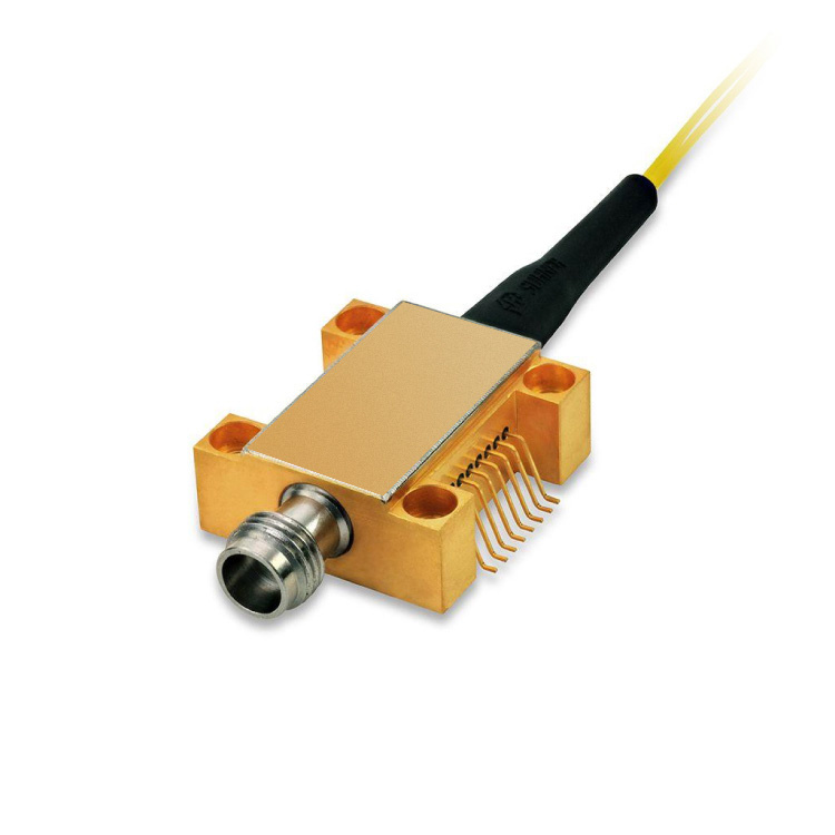
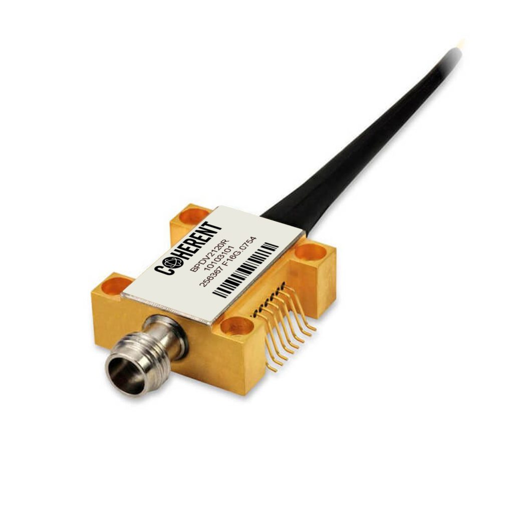
- Figure 1 — BPDV2120R product photo: gold hermetic butterfly package, V® %s RF output connector on the front, two single-mode fibre pigtails at the rear (example photo; the actual unit may differ; source: Coherent official datasheet, RF connector label may differ)
- Figure 2 — Typical O/E bandwidth response S21: flatness better than 1 dB from DC to about 20 GHz, 3 dB bandwidth beyond the 40 GHz line (source: Coherent official datasheet, RF connector label may differ)
- Figure 3 — Typical output return loss S22: below the −3 dB specification line across the band, better than −15 dB in the low/mid frequencies (source: Coherent official datasheet, RF connector label may differ)
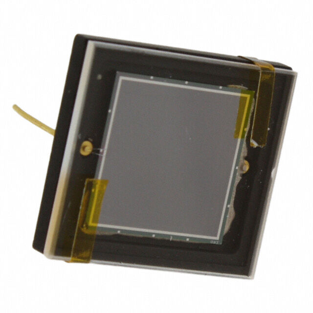
- Figure 4 — BPDV21x0R series waveguide-integrated dual-photodiode chip (source: Coherent product materials)
BPDV2120R vs BPDV2150R Selection
The two share identical chip structure, package, interfaces and bandwidth — the only difference is polarisation-dependent loss (PDL). BPDV2120R is the standard version (PDL ≤0.4 dB) and BPDV2150R the low-PDL version (PDL ≤0.2 dB). PDL means how much the responsivity changes as the polarisation state of the incident light rotates. The table below helps selection by system polarisation budget.
| Item | BPDV2120R (this page) | Coherent BPDV2150R |
|---|---|---|
| Item | BPDV2120R (this page) | Coherent BPDV2150R |
| Version | Standard PDL version (model x = 2) | Low-PDL version (model x = 5) |
| 3 dB cutoff | 42 GHz (C-band, specification value) | 42 GHz (C-band, specification value) |
| Optical window | C-band 1525–1575 nm | C-band 1525–1575 nm |
| DC responsivity | ≥0.4 A/W (best polarisation) | ≥0.4 A/W (best polarisation) |
| PDL | 0.4 dB (typ) / 0.8 dB (max) | 0.2 dB (typ) / 0.4 dB (max) |
| Responsivity imbalance | Typ. 0.15 dB | Typ. 0.15 dB |
| Dark current | 5 nA (typ) / 200 nA (max) | 5 nA (typ) / 200 nA (max) |
| Typical scenarios | Coherent detection with controlled polarisation or PM-fibre input, microwave photonics links; general T&M | Field/free-space coupling links with uncontrolled polarisation, polarisation-multiplexed coherent reception, polarisation-sensitive calibration setups |
| Note: BPDV2150R is also available in dual-pair (RM) and quad-set (RQ) configurations for polarisation-diversity coherent reception; for connector customisation and fibre matching services, contact us to confirm with the manufacturer. Without polarisation control in the system, the low-PDL version is recommended. |
Typical Applications
- 43 Gb/s coherent communication systems and DWDM transmission R&D: coherent receiver front ends, demodulation and polarisation-diversity experiments
- Microwave photonics: photonic generation of microwaves, microwave photonic filters and receiver ends of analogue optical links
- Analogue optical links and radio-over-fiber: photoelectric conversion with high linearity requirements
- High-speed test & measurement: device frequency response / eye diagram / pulse characterisation (to 35 GHz), O/E conversion front ends
- Advanced device R&D: differential laser RIN measurement, common-mode noise suppression measurement
- High-sensitivity differential detection: precise amplitude/phase comparison of two optical signals
Downloads
- Coherent BPDV21x0R Official Datasheet (PDF, © 2023) — key specification tables, typical S21 bandwidth and S22 return-loss curves, selection rules and package outline.
- Thorlabs Balanced Detectors (BDX3 / PDB4xx series) — amplified lab alternatives for comparison.
If you need earlier-edition specifications (with absolute maximum ratings and environmental test data), a RoHS declaration or application notes, our engineers can request them from the manufacturer on your behalf.
Frequently Asked Questions (FAQ)
Q: What is the CBPDV2120R detector, and how is the suffix read?
A: It is Coherent’s 43 GHz balanced photodetector, converting differential optical signals in the C-band to RF. The model rule is BPDV21x0R-Vy-zz: x = 2 means the standard PDL version (x = 5 is the low-PDL BPDV2150R); y is the RF connector, VF = V® female, VM = V® male; zz is the fibre interface, FP = FC/PC (standard) and FA = FC/APC. For the CBPDV2120R the connector options are confirmed at order (RF: VF female / VM male; fibre: FP FC/PC / FA FC/APC).
Q: Is an external bias tee needed? How is it powered?
A: No. The BPDV21x0R bias network is integrated inside the chip and package, keeping the response undisturbed from DC to the 3 dB cutoff — one of its core design differences from ordinary high-speed balanced detectors. Power the two PDs separately: VPD1 (Pin 14) +2.0 to +3.3 V, VPD2 (Pin 3) −3.3 to −2.0 V, typically ±2.8 V; Pins 2/15 are ground (chassis), Pin 17 is the RF output. The two bias voltages need not be symmetric but must stay within specification.
Q: What data rate corresponds to the 43 GHz bandwidth? How fast an optical signal can be measured?
A: The 3 dB cutoff is specified at 42 GHz (C-band) with a flat response from DC. As a rough correspondence, 42 GHz of electrical bandwidth supports NRZ testing at about 40–43 Gb/s. The manufacturer explicitly recommends an application limit of 35 GHz (microwave photonics and T&M scenarios) because the response rolls off near the cutoff and small group-delay variations must be budgeted. For more bandwidth, the same product line offers 70 GHz (BPDV3x20Rv) and 100 GHz (BPDV412xRv) balanced detectors.
Q: How do I choose between BPDV2120R and BPDV2150R?
A: The only difference is PDL: BPDV2120R standard PDL ≤0.4 dB, BPDV2150R low PDL ≤0.2 dB. If your optical path has polarisation control (PM fibre, polarisation controller, or fixed input polarisation), BPDV2120R is sufficient; if the polarisation state drifts over time (field fibre, free-space coupling, long ordinary single-mode runs), PDL appears as slow output-amplitude drift with polarisation — choose BPDV2150R. For polarisation-multiplexed coherent reception, go straight to the low-PDL version or even dual-pair/quad sets.
Q: How does it differ from Thorlabs balanced detectors (BDX / PDB series), and when should I choose it?
A: They have different positions. Thorlabs BDX / PDB series are laboratory general-purpose balanced detectors with built-in transimpedance amplification or adjustable gain, bandwidths concentrated around DC–5 GHz, and free-space or large-core fibre inputs, aimed at spectroscopy and general optical-power differencing; this device is a telecom-grade unamplified photodiode module with 42 GHz bandwidth, single-mode fibre input and a 50 Ω RF interface for coherent communications, microwave photonics and high-speed time/frequency-domain measurement, requiring an external receiver amplifier or direct oscilloscope connection. In short: for slow signals needing gain choose BDX/PDB; for fast signals above 10 GHz needing faithful frequency response choose BPDV21x0R. Our site also carries the Thorlabs RXM series 10–42 GHz ultra-fast fibre-optic receivers (single-ended) for comparison if balanced differencing is not required.
Q: What is the maximum input optical power, and how linear is it?
A: Key datasheet figures: average optical input power up to 13 dBm; characterised as linear within 10 dBm. The waveguide structure’s high-power tolerance clearly exceeds ordinary planar photodiodes. In engineering practice keep the normal operating point within 10 dBm with margin; over-specification input may cause permanent damage and is not covered by warranty.
Q: Is it in stock? What is the lead time? What does the price include?
A: It is a make-to-order item; lead time is subject to our confirmation with the manufacturer — for urgent needs please check in-transit stock with us first. The tax-inclusive price shown on this page (13% VAT included) is our RMB selling price, minimum order 1 unit in the manufacturer’s standard package; volume purchasing, connector customisation (FC/APC, V® male, etc.) and fibre-matching services can be quoted separately.
Ordering Information
Ordering model: CBPDV2120R (manufacturer: Coherent Corp). Series selection rule BPDV21x0R-Vy-zz: x = 2 standard PDL / 5 low PDL; y = VF V® female (standard) / VM V® male; zz = FP FC/PC (standard) / FA FC/APC. Dual-pair (RM) and quad-set (RQ) custom configurations are also available for polarisation-diversity coherent reception.
For matching low-noise DC bias sources, RF cables and adapters, transimpedance-amplifier evaluation boards, or factory-screened / calibrated versions, contact our engineers for a solution and quotation.
Disclaimer
Parameters, curves and interface data on this page are compiled from the Coherent official datasheet “43 GHz Balanced Photodetector BPDV21x0R” (© 2023 Coherent Corp), the Coherent product-line pages and public product materials (collected 2026-11-04) and cross-checked; actual product parameters, appearance and packaging are subject to the manufacturer’s shipment, and specifications may change without notice.
This product is an electrostatic-sensitive device — take ESD precautions when handling; bias voltages, optical power or temperature beyond specification may permanently damage the device, and such losses are not covered by warranty.
The product is intended for lawful scientific research, industrial and similar uses only. Coherent and V® are trademarks of their respective owners and are used here for product description only.
Reviews
There are no reviews yet.