


Laser-Induced Damage Threshold (LIDT) Calculator
Calculate laser fluence and power density, assess the damage risk to optical components, and help you select optical components and laser parameters appropriately
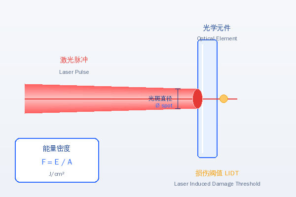
⚡ Laser Damage Threshold Calculator
Enter laser parameters to calculate energy density and power density, and determine whether they exceed the damage thresholds of common optical components
💡 Tip: the peak energy density of a Gaussian beam is twice the average, and damage usually occurs at the peak
Damage Thresholds of Common Optical Components
Typical damage threshold reference values at 1064 nm wavelength and 10 ns pulse duration
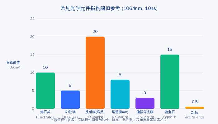
Fused silica
High transmission from ultraviolet to infrared
~10 J/cm² @ 1064nm, 10ns
High-purity synthetic silica glass, the most widely used optical material in high-power laser systems. It offers extremely low absorption and excellent optical homogeneity.
K9 glass (BK7)
Borosilicate crown glass
~5 J/cm² @ 1064nm, 10ns
The most commonly used optical glass, offering good value for money. Owing to its impurity content, its damage threshold is lower than that of fused silica.
High-reflection coating (HR)
dielectric coating
~2-20 J/cm² @ 1064nm, 10ns
Multilayer dielectric mirrors whose damage threshold varies widely with coating design and fabrication process. Laser damage usually initiates in the coating.
Anti-reflection coating (AR)
Anti-Reflection
~5-15 J/cm² @ 1064nm, 10ns
Single- or multilayer anti-reflection coatings used to reduce reflection at optical surfaces. The fewer the layers, the higher the damage threshold generally is.
Polarising beamsplitter coating (PBS)
Polarizing Beam Splitter
~2-5 J/cm² @ 1064nm, 10ns
A polarising beamsplitter coating used to separate s- and p-polarised light; its layer structure is complex and its damage threshold is usually relatively low.
Zinc selenide (ZnSe)
Mid-infrared material
~0.5 J/cm² @ 10.6μm, CW
The most commonly used optical material for CO₂ lasers, with high transmission in the mid-infrared. However, its thermal conductivity is relatively low, limiting the continuous-wave power density.
Core LIDT Calculation Formulas
Master the calculation of energy density and power density to accurately assess laser damage risk
Meaning:Pulse energy per unit area, a common parameter for the damage threshold of pulsed lasers. E_p is the single-pulse energy and A is the spot area.
Meaning:Average power per unit area, a common parameter for the damage threshold of continuous-wave lasers. P_avg is the average power.
Meaning:The peak power density during a pulse. τ is the pulse duration. Damage from ultrashort (fs) pulses is determined by the peak intensity.
Principal Mechanisms of Laser Damage
Laser damage mechanisms differ markedly across pulse duration ranges
🔵 Ultrashort pulses (fs) — multiphoton ionisation
The pulse duration of a femtosecond laser is far shorter than the electron–phonon relaxation time, so energy is transferred directly to the electrons. Throughmultiphoton ionisationandtunnel ionisationchemical bonds are broken directly. The damage threshold is low, almost independent of pulse duration, and determined by the peak intensity (typically of the order of ~10¹³ W/cm²).
🔴 Nanosecond pulses — thermal damage
Damage from ns pulses is mainlya thermal effect: absorbed laser energy is converted into heat, causing local temperature rise, melting and even vaporisation. The damage threshold is proportional to the square root of the pulse duration (the √τ law). This is the most common damage mechanism in industrial lasers.
🟡 Continuous-wave lasers — thermal deformation / thermal fracture
CW laser damage is mainly caused bysustained heat accumulation. Fracture occurs when the thermal stress from the temperature gradient exceeds the strength limit of the material. Thermal lensing in ZnSe lenses of high-power CO₂ lasers is also a common problem. The damage threshold is usually expressed as power density (W/cm²).
⚠️ High-repetition-rate pulses — cumulative effects
High-repetition-rate pulses (e.g. MHz) can cause damage throughheat accumulationeven when the single-pulse energy is below the LIDT. When the repetition rate is high enough that the pulse interval is shorter than the thermal diffusion time, heat cannot dissipate and the temperature accumulates pulse by pulse. In this case both the average power density and the single-pulse energy density must be considered.
Common Misconceptions
Avoid these LIDT misunderstandings to ensure safe operation of the optical system
‘If the average power is below the rating, it is safe’
Wrong! For pulsed lasers it is thepeak power densitythat is key to damage. For a 100 W, 10 ns, 10 kHz laser with a single-pulse energy of 10 mJ and a 100 μm spot, the peak power density can reach1.27×10⁹ W/cm², far exceeding the CW damage threshold. For pulsed lasers both the energy density (J/cm²) and the peak power density must be checked.
Using average power / spot area to assess damage
Damage in pulsed lasers cannot be calculated from average power! You must usesingle-pulse energy ÷ spot areato obtain the energy density (J/cm²), then divide by the pulse duration to get the peak power density. The LIDT quoted by manufacturers (e.g. 10 J/cm² @ 10 ns) is a pulse energy density parameter referring to a single pulse, not an average.
LIDT is an absolute value — staying below it is safe
LIDT is a statistical value, not an absolute one! Damage isa probabilistic event, strongly dependent on surface defects, coating quality, pulse count and so on. The value usually quoted is the 1-on-1 (single-pulse) LIDT; the N-on-N (multiple-pulse) LIDT is lower. It is advisable to allow at least a2–3 times safety margin。
‘Use the average energy density for a Gaussian beam’
A dangerous mistake! The centre intensity of a Gaussian beam is several times that at the edge, anddamage always occurs first at the peak. For a Gaussian beam the peak energy density is F_peak = 2 × F_avg (average). Calculations must compare the peak density with the LIDT; otherwise one may wrongly conclude that the beam is ‘safe’ when damage has in fact already occurred.
LIDT at different pulse durations can be compared directly
No! LIDT must state the test pulse duration. The LIDT (J/cm²) of ns pulses is far higher than that of fs pulses, but their peak power density is far lower. As a rough estimate:In the ns range (1 ns–1 μs), LIDT ∝ √τ. From 10 ns to 100 ns, the LIDT increases by about √10≈3.2 times.
Coating and substrate LIDT are the same
The damage threshold of a coated componentis usually lower than that of a bare substrate! Coating interfaces, nodular defects and absorbing layers are damage initiation sites. Particular care is needed with AR and PBS coatings. High-reflection (HR) coatings have relatively high LIDT, but this also depends on the coating design and fabrication process. When selecting high-power optical components, always confirm the coating LIDT.
Calculation Examples
Learn LIDT calculation methods through practical examples
Safety margin assessment for fibre laser marking
Average powerP = 50 W
Pulse durationτ = 100 ns
Repetition ratef = 100 kHz
Spot diameterØ = 50 μm
- Single-pulse energy:E_p = P/f = 50W / 100kHz = 0.5 mJ
- Spot area (1/e²):A = π·(d/2)² = π × (25×10⁻⁴cm)² = 1.96×10⁻⁵ cm²
- Average energy density:F_avg = E_p/A = 0.5×10⁻³J / 1.96×10⁻⁵cm² = 25.5 J/cm²
- Peak energy density (Gaussian):F_peak = 2 × F_avg = 51 J/cm²
- Peak power density:I_peak = F_peak/τ = 51 J/cm² / 100×10⁻⁹s = 5.1×10⁸ W/cm²
Conclusion: the peak energy density of 51 J/cm² far exceeds the damage threshold of fused silica (~10 J/cm²), indicating a serious damage risk!
Power density calculation for a CO₂ continuous-wave laser lens
PowerP = 500 W (CW)
Spot diameterØ = 20 mm
- Spot area:A = π·(1cm)² = 3.14 cm²
- Average power density:I_avg = P/A = 500W / 3.14cm² ≈ 159 W/cm²
- Peak power density (Gaussian):I_peak = 2 × I_avg = 318 W/cm²
Conclusion: the CW damage threshold of a ZnSe lens is normally >1 kW/cm²; the peak of 318 W/cm² provides an adequate safety margin, so it can be used safely.