


Fibre Coupling Efficiency Calculator
Calculate the theoretical coupling efficiency between a Gaussian beam and a single-mode fibre, assess the effects of alignment error and angular misalignment, and optimise fibre coupling system design
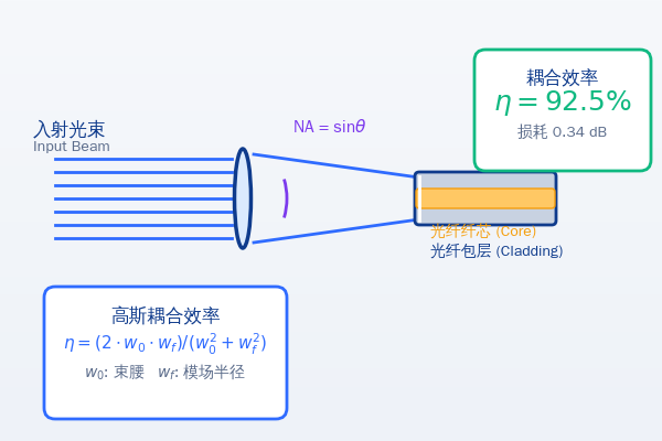
🔗 Fibre Coupling Efficiency Calculator
Enter the beam and fibre parameters to calculate the theoretical coupling efficiency, coupling loss and the effect of alignment deviations
M²
NA
💡 Tip: maximum coupling efficiency occurs when the beam waist diameter equals the fibre mode field diameter and alignment is exact
Common single-mode fibre parameters
Reference values of mode field diameter and numerical aperture for standard single-mode fibres
| Fibre type | Operating wavelength | Mode field diameter (MFD) | Numerical aperture (NA) | Typical applications |
|---|---|---|---|---|
|
SMF-28 |
1310/1550 nm | 9.2 μm @1310nm 10.4 μm @1550nm |
0.14 | Optical fibre communications, fibre lasers |
|
HI1060 |
980/1064 nm | 6.2 μm @980nm 6.6 μm @1064nm |
0.14 | Fibre lasers, amplifiers |
|
Polarisation-maintaining fibre (PM) |
780/1064/1550 nm | 5.2~10.5 μm (depends on the model) |
0.11~0.14 | Interferometry, fibre sensing |
|
Multimode fibre |
Visible ~ infrared | 50/62.5/105 μm (core diameter) |
0.22 | High-power delivery, illumination |
|
LMA large mode area fibre |
1064 nm | 20~30 μm (mode field diameter) |
0.06~0.08 | High-power fibre lasers |
Core coupling efficiency formulas
Theoretical basis of Gaussian beam to single-mode fibre coupling
Effect of alignment errors on coupling efficiency
Sensitivity analysis of the three types of alignment error
🔴 Lateral offset — most sensitive
Lateral (perpendicular to the optical axis) offset is the error source with thegreatestimpact on coupling efficiency. For a single-mode fibre (MFD≈10 μm), a 1 μm offset causes about 2% efficiency loss, 2 μm about 8% and 5 μm can reach 40% loss. Precision fibre coupling requires nanometre-scale lateral alignment accuracy.
🟡 Angular misalignment — moderately sensitive
The sensitivity to angular misalignment depends on the mode field size and wavelength. For SMF-28 at 1550 nm, an angular deviation of 1° (about 17 mrad) causes about 3 dB (50%) loss. Fibres with a small MFD are more sensitive to angular error. In practical systems this is usually reduced bylens collimation + focusingto reduce the effect of angular error.
🟢 Axial misalignment — least sensitive
Axial (along the optical axis) offset usually has the smallest effect. As long as the waist position lies within the Rayleigh range, the efficiency drop is negligible. A system with MFD = 10 μm at 1550 nm has a Rayleigh range of about500μm, meaning an axial offset of 100 μm causes only about 4% efficiency loss.
⚠️ Combination of the three errors
In practical systems all three errors coexist, and the overall coupling efficiency is approximately theproductof the individual efficiencies (first-order approximation). For example: lateral offset loses 10% (η = 0.9), angular misalignment loses 15% (η = 0.85) and axial misalignment loses 5% (η = 0.95), giving a total efficiency ≈ 0.9 × 0.85 × 0.95 ≈ 72.7%. Precision alignment systems can usually achieve coupling efficiencies above 80%.
Methods to improve fibre coupling efficiency
Practical engineering tips to achieve the best coupling results
Mode field matching
Mode Field Matching
The most critical factor
Choose a suitable focusing lens so that the focused waist diameter exactly equals the fibre mode field diameter. Options include aspheric lenses, gradient-index (GRIN) lenses or microscope objectives.
Precision alignment
Precision Alignment
Nanometre-scale accuracy
Use a six-axis stage (three translation plus three rotation axes) for precise positioning. Active alignment (monitoring the coupled power in real time) is far more accurate than passive alignment.
Fibre end-face preparation
Fiber End Face
Avoid end-face reflection
Ensure the fibre end face is cleaved flat and clean. If necessary, use angle polishing (APC, 8°) to reduce Fresnel reflection, or apply an anti-reflection coating.
Beam quality
Beam Quality M²
The closer M² is to 1, the better
A single-mode fibre can only excite the fundamental mode; energy in higher-order modes of the beam cannot couple into it. The larger the M², the lower the coupling efficiency.
NA matching
NA Matching
Avoid angular mismatch
The divergence angle of the incident beam must be smaller than the fibre numerical aperture (NA); otherwise, high-angle rays cannot be confined by the fibre waveguide and leak from the cladding.
Fibre couplers
Fiber Coupler
Integrated solution
Commercial fibre couplers integrate the lens and fibre into one unit, precisely aligned before leaving the factory, so only the input beam needs to be adjusted in use.
Calculation examples
Learn fibre coupling efficiency calculation through practical examples
Coupling a 1064 nm laser into HI1060 fibre
Focused waist2w₀ = 6.6 μm
M² = 1.1
Fibre MFD6.6 μm
Lateral offsetΔx = 0.5 μm
- Optimal match efficiency (size matching):η₀ = 4·3.3·3.3 / (3.3² + 3.3²) = 100% (ideal alignment)
- Effective mode field radius:w_eff = √(3.3² + 3.3²) = 4.67 μm
- Effect of lateral offset:η_x = exp(-2×0.5²/4.67²) = exp(-0.023) = 0.977 = 97.7%
- M² correction:Actual coupling efficiency ≈ η × (1/M²) = 97.7% × (1/1.1) ≈ 88.8%
- Coupling loss:Loss = -10·log₁₀(0.888) = 0.52 dB