


Single-Lens Focal Length Calculator
Based on the lensmaker equation; enter the refractive index and radii of curvature to quickly calculate the lens effective focal length, optical power and back focal length, with automatic lens type determination
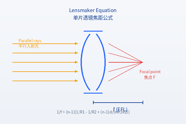
🔍 Single-Lens Focal Length Calculator (lensmaker equation)
Enter the lens parameters to calculate the effective focal length, optical power and back focal length in real time
n
mm
mm
mm
💡 Tip: for a flat surface, enter 0 or leave blank (treated as R=∞, 1/R=0). Sign rule for R: positive when the centre of curvature lies to the right of the vertex, negative when to the left.
📊 Thin-lens approximation comparison (d≈0)
Thin-lens approximate focal length:— mm; difference from the thick-lens result:—
Sign convention for radius of curvature
Understanding the sign of R is the key to using the lensmaker equation correctly
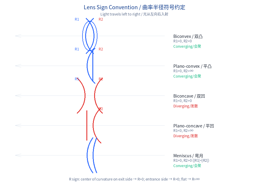
Figure: sign conventions for the radius of curvature of five common lens types. Light travels from left to right.
📏 Sign rules (optical convention)
Light travels from left to right. The sign of the radius of curvature R depends on which side of the surface vertex thecentre of curvaturelies:
• Centre of curvature to theright of the vertex(exit-light side) →R is positive
• Centre of curvature to theleft of the vertex(incident-light side) →R is negative
• Flat surface: R = ∞ (enter 0 or leave blank in the tool; treated as 1/R=0)
⚠️ Key point: the sign of R does not depend on whether the surface is “convex” but on which way it bulges — the same convex surface is positive as the first surface (S1) and negative as the second surface (S2).
| Lens type | First surface R₁ | Second surface R₂ | Optical power | Example |
|---|---|---|---|---|
| Biconvex | + (positive) | − (negative) | Converging (+) | R₁=100, R₂=-100 |
| Plano-convex (convex surface facing the light) | + (positive) | ∞ (flat) | Converging (+) | R₁=100, R₂=∞ |
| Plano-convex (flat surface facing the light) | ∞ (flat) | − (negative) | Converging (+) | R₁=∞, R₂=-100 |
| Biconcave | − (negative) | + (positive) | Diverging (−) | R₁=-100, R₂=100 |
| Plano-concave (concave surface facing the light) | − (negative) | ∞ (flat) | Diverging (−) | R₁=-100, R₂=∞ |
| Plano-concave (flat surface facing the light) | ∞ (flat) | + (positive) | Diverging (−) | R₁=∞, R₂=100 |
| Meniscus (positive meniscus) | + (positive) | + (positive), |R₁|<|R₂| | Converging (+) | R₁=50, R₂=100 |
| Meniscus (negative meniscus) | − (negative) | − (negative), |R₁|<|R₂| | Diverging (−) | R₁=-50, R₂=-100 |
The lensmaker equation and core formulas
Focal length calculation methods for thick and thin lenses
Thick-lens lensmaker equation
Purpose:Accurately calculate the lens effective focal length (EFL). Applies to single lenses of any thickness in air (n_air≈1). φ is the optical power (in dioptres D = m⁻¹) and f is the effective focal length.
Thin-lens approximation (d≈0)
Purpose:When the lens thickness d is much smaller than the radii of curvature, the third term can be neglected. The thin-lens formula is simpler and often used for quick estimates. This calculator gives both thick- and thin-lens results for easy comparison.
Back focal length BFL (back vertex focal length)
Purpose:The distance from the last surface of the lens (the back vertex) to the rear focal point. In optomechanical design, the BFL determines how much space must be reserved behind the lens for a detector or other components.
Optical power
Meaning:The optical power φ is the reciprocal of focal length and characterises the ability of a lens to converge or diverge a beam. φ>0 is a converging (positive) lens and φ<0 a diverging (negative) lens. Eyeglass power = φ×100.
Refractive indices of common laser optical materials
Refractive index varies with wavelength; use the value at the actual operating wavelength
| Material | Typical refractive index n | Reference wavelength | Common applications |
|---|---|---|---|
| N-BK7 / H-K9L | 1.517 | d-line (587.6 nm) | General-purpose visible–near-IR substrate |
| Fused Silica | 1.458 / 1.449 | 589nm / 1064nm | UV–IR windows, high-power lasers |
| CaF₂ calcium fluoride | 1.434 | d-line | UV–mid-IR, low dispersion |
| Sapphire (o-ray) | 1.768 | d-line | Hard windows, protective windows |
| ZnSe zinc selenide | 2.40 | 10.6 μm | CO₂ laser lenses/windows |
| Ge germanium | 4.0 | 10.6 μm | Thermal imaging, CO₂ lasers |
| Si silicon | 3.42 | 10.6 μm | Mid-IR optics |
| SF11 flint glass | 1.785 | d-line | High refractive index, achromatic design |
| F2 flint glass | 1.620 | d-line | Achromatic doublets |
⚠️ The above are approximate values; for precise refractive indices, consult the material supplier’s Sellmeier coefficient table. Refractive index varies with wavelength (dispersion), so the same material has different n at different wavelengths.
Common misconceptions
Avoid these misunderstandings about lens focal length calculation
“The sign of R depends on whether the surface is convex”
Wrong! The sign of R depends onwhich side the centre of curvature is on, not on whether it is convex. The same convex surface is positive as the first surface (the one the light strikes first) and negative as the second surface. Remember the rule:“Centre of curvature to the right: R positive; centre to the left: R negative”(light travels from left to right).
“Thin-lens and thick-lens formulas are the same”
They are not the same. The thin-lens formula neglects the effect of thickness d (the third term of the lensmaker equation). For a thin lens with d < 1 mm the difference is <0.1%; but at d = 10 mm and R = 50 mm it can reach 2–5%. Precision optical design must use the thick-lens formula.
“EFL = BFL; all focal lengths are the same”
The EFL (effective focal length) is the distance from the principal plane to the focal point; the BFL (back focal length) is the distance from the last surface of the lens to the focal point. The two are only approximately equal for a thin lens (d≈0). For a thick lens, BFL = f × [1−(n−1)d/(nR₁)], which depends on R₁ and d.
“Entering R=0 for a flat surface will cause an error”
No. In this tool, R=0 or a blank entry represents R=∞ (a flat surface), so 1/R=0 and the corresponding term disappears from the formula. This is precisely the correct way for the lensmaker equation to handle a flat surface — it makes no contribution to optical power.
“Meniscus lenses always diverge”
Not necessarily. A meniscus lens (R₁ and R₂ of the same sign) may either diverge or converge, depending on the difference in curvature between the two surfaces. When |R₁| < |R₂| and both are positive, the net effect is converging; otherwise it is diverging. The key is the sign of 1/R₁ − 1/R₂.
“The shorter the focal length, the better the lens”
There is no “best” focal length, only the “most suitable” one. A short focal length means high optical power and a small spot, but also a short working distance and shallow depth of field. Laser cutting commonly uses f-theta lenses with f = 50–200 mm, while laser collimation uses long-focus lenses with f above 500 mm.
Related lens products
Soar Laser supplies a wide range of laser lenses; contact our technical team for selection support
Thorlabs LA1353 plano-convex lens
N-BK7, Ø75 mm, f = 200 mm, uncoated. Suitable for visible–near-IR laser focusing and collimation.
Plano-convex lens
N-BK7
f=200mm
Thorlabs LA1002 plano-convex lens
N-BK7, Ø75 mm, f = 150 mm, uncoated. Commonly used in laser marking and welding focusing optics.
Plano-convex lens
N-BK7
f=150mm
Thorlabs ACY254-200-B cylindrical achromatic doublet
Ø25.4 mm, f = 20 mm, B coating (650–1050 nm). Achromatic design for broadband focusing.
Achromatic lens
Broadband
JG-SL-1064 F-Theta scanning lens
Dedicated to 1064 nm, focal length 110 mm, scan field 163 mm. A core component of laser marking galvanometer systems.
F-theta lens
1064nm