


1. How Bad Can a Wrong F-Theta Lens Be?
If you build laser equipment, have you ever run into these maddening situations—
- Lines as thick as brush strokes, with customers complaining about “insufficient precision”?
- The galvo feels “weak” while scanning, and edge marking always comes out shallow and faint?
- You upgraded to a higher-power laser source, yet results still will not improve?
- The working distance does not match—either the beam cannot reach the workpiece, or it sits too far and defocuses?
- After adding coaxial vision, the red light and the laser simply refuse to share one focal point?
Before blaming the laser source or the galvo scanner—90% of these problems trace back to the wrong F-Theta lens.
The F-Theta lens (flat-field focusing lens) is the last and most critical lens component in a laser processing beam path. It determines spot size, scan field, working distance, and edge uniformity… Choose the right one and the machine performs to its full potential; choose the wrong one and even the most powerful laser is wasted.
In this article, I will cover in full the 9 core selection parameters, the pairing rating table, coaxial vision matching, thermal lensing, and the galvo welding chapter. After reading this, you will never step into a pit when selecting an F-Theta lens again.
⚠️ Note: this article is long—bookmark it and refer back repeatedly. When selecting, cross-check the quick-reference tables at the end to get it right the first time.
Before we officially start, clarify one most fundamental question—does your laser output a point source or quasi-parallel light? I expect many readers are stopped cold by this question. Let me briefly describe it the way I understand it:
It is simple—look at the laser output interface. If your laser’s output end is a fiber interface (QBH, QD, FC, SMA, D80, etc.—the kind with a fiber connector head), the light comes out of a fiber only a few tens of microns thick, so the output is divergent, like a light bulb—that is a point source. CW fiber lasers and some pulsed fiber lasers (those with fiber output interfaces) are of this type.
If the light from your laser is already a quasi-parallel beam (a few millimeters thick, barely diverging), that is quasi-parallel light. Pulsed fiber, QCS, Q-switched, MOPA, CO2 RF-tube, and green/UV solid-state lasers all output this type.
F-Theta lens selection splits into two paths: one is the quasi-parallel light path, which we call Path A here; the other is the point-source path, which we call Path B here.
One-sentence rule: does your laser need a collimator? Yes → Path B, No → Path A.
This determines your entire selection route:
| Laser Output Type | Typical Lasers | Beam Path | Core Formula |
|---|---|---|---|
Path A: quasi-parallel light |
Pulsed fiber, Q-switched, MOPA, CO2 RF tube, green/UV solid-state |
Beam expander → galvo scanner → F-Theta lens |
Φ₀ = 4M²λf/(πΦ) |
Path B: point source/divergent light |
CW fiber lasers |
Collimator → galvo scanner → F-Theta lens |
d = (d_fiber × f_f) / f_c |
👉 For Path A, read Chapters 2–7; for Path B, jump straight to Chapter 8. The formulas of the two paths must not be mixed!
2. Path A (Quasi-Parallel Light) Core Formula: Get the Four-Element Relationship Straight
⚠️ Note: the formulas and rules below apply to Path A laser systems. If you build Path B laser systems, the beam path and formulas are completely different—jump straight to Chapter 8.
Before the specific parameters, Path A systems must first remember this iron rule—
Laser output beam diameter × beam expander ratio ≤ galvo aperture ≤ F-Theta entrance pupil
This chain determines whether the whole beam path can “pass through”:
- Laser output beam diameter: the diameter of the quasi-parallel beam leaving the laser aperture. Some laser manuals call it output beam, others beam diameter, others 1/e², and still others beam waist diameter.
- Beam expander ratio: 2×, 3×, 4×, 5×, 6×, 8×, etc. The expander enlarges the beam so that the focused spot becomes smaller.
- Galvo aperture: the maximum beam diameter the galvo mirrors can accept; commonly 10mm, 12mm, 15mm, 20mm, 25mm, 30mm.
- F-Theta entrance pupil: the maximum incident beam diameter the F-Theta lens can accept; commonly 10mm, 12mm, 14mm, 15mm, 20mm, 25mm, 30mm.
⚠️ Pitfall case: a 20W fiber marking machine had a laser output beam of 6.5mm with a 2× expander, giving an output beam of 13mm—but the galvo was fitted with only 10mm mirrors. The beam was clipped at the mirror edges, edge light was lost outright, and marks came out bright in the center and dim around the edges.
Speed First vs. Precision First
The choice in this beam-path chain directly determines whether you take the “speed-first” or the “precision-first” route:
| Route | Expander Ratio | Galvo Mirror Size | Focused Spot | Typical Use |
|---|---|---|---|---|
| Speed first | Low ratio (2×–3×) | Small mirrors → faster galvo response | Larger | On-the-fly marking, large-character coding |
| Precision first | High ratio (4×–8×) | Large mirrors → slower galvo response | Smaller | Fine marking, micromachining |
Remember: the larger the expansion ratio, the smaller the focused spot, but the slower the galvo response. It is a trade-off—a unity of opposites, with no solution that has it both ways.
3. Path A Laser Systems: The 9 Key F-Theta Lens Selection Parameters
① Operating Wavelength: Must Match
The F-Theta coating is designed for specific wavelengths; a wavelength mismatch means transmission collapses.
| Wavelength | Type | Typical Applications |
|---|---|---|
| 1064nm | Near-infrared | Fiber/Nd:YAG marking, cutting |
| 10600nm | Far-infrared | CO₂ cutting, marking |
| 532nm | Green | Precision cutting, wafer scribing |
| 355nm | Ultraviolet | Micromachining, flexible materials |
| 9.3μm 9.4um 10.2um | Far-infrared | Also CO2 laser wavelengths—for PET (polyethylene terephthalate), PI polyimide (Kapton), LCD polarizers, FR4/FR2 printed circuit boards, etc. |
⚠️ Pitfall alert: firing 532nm green light through a 1064nm F-Theta lens can drop transmission from 99.5% to below 60%—more than 1/3 of the power lost! The focal position also shifts, because refractive index depends on wavelength. F-Theta lenses for different wavelengths must never be mixed.
② Path A Laser Systems—Scan Field and Focal Length: Field ≈ 0.7 × Focal Length
This is the most intuitive selection parameter. There is an approximate relationship between the focal length (f) of the F-Theta lens and the scan field (diagonal):
Scan field (diagonal) ≈ 0.7 × focal length f
Common reference table:
| Focal length f (mm) | Field (mm × mm) | Diagonal (mm) | Typical Application |
|---|---|---|---|
| F100 | 70×70 | ~99 | Precision micromachining |
| F160 | 110×110 | ~156 | Small-part marking |
| F210 | 150×150 | ~212 | Standard marking |
| F254 | 175×175 | ~247 | General-purpose marking |
| F330 | 220×220 | ~311 | Large-format marking |
| F420 | 300×300 | ~424 | Large format/cutting |
| F525 | 360×360 | ~509 | Ultra-large-format cutting |
⚠️ Pitfall alert: a bigger field is not automatically better! The F525 field is more than 5× that of F100, but the focused spot is also 5× larger—try to mark a fine QR code with F525 and it simply will not resolve. Choose the field from actual needs and just leave a 10%–15% margin.
③ Path A Laser Systems—Entrance Pupil: The Most Common Mistake!
The entrance pupil is the maximum beam diameter the F-Theta lens can accept. This is the most common mistake equipment builders make, bar none.
Why? Because many people look only at focal length and field size and completely ignore the entrance pupil. The result is—
⚠️ Weak edge light, shallow marks near the corners, more obvious the larger the field—this is almost 100% caused by an insufficient entrance pupil!
The principle is simple: if the beam diameter exceeds the F-Theta entrance pupil, then when the galvo mirrors tilt to their maximum angle, the reflected beam extends beyond the F-Theta lens aperture, and the excess light is clipped off by the lens edge. Center light still passes normally, while loss grows toward the edges.
In machining terms: deep in the center, shallow at the edges.
⚠️ Pitfall case: an integrator paired a 30W Coherent C30A laser with a 6× CO2 beam expander and picked a cheap CO2 F-Theta lens with only a 38mm lens diameter—and a 38mm lens diameter implies an entrance pupil of just 10mm. The C30A beam diameter is 2mm, so after the expander the beam leaving it is 2*6=12mm. The lens was rated for a 110*110mm field—yet the result was shallow marking in the outer 10% of the field, i.e., marking depth clearly dropped in the 98–110mm zone. The problem was solved immediately after switching to a 48mm-diameter CO2 lens with a 12mm entrance pupil.
Selection advice: the entrance pupil should at least be ≥ the expanded beam diameter, and a small margin is recommended.
Dynamic Relationship Between Entrance Pupil and Field
Most F-Theta datasheets list a nominal marking field or marking range, but for the same lens the actual field varies dynamically—it depends on the match between entrance pupil and galvo scan angle. This is the key point 90% of equipment builders overlook.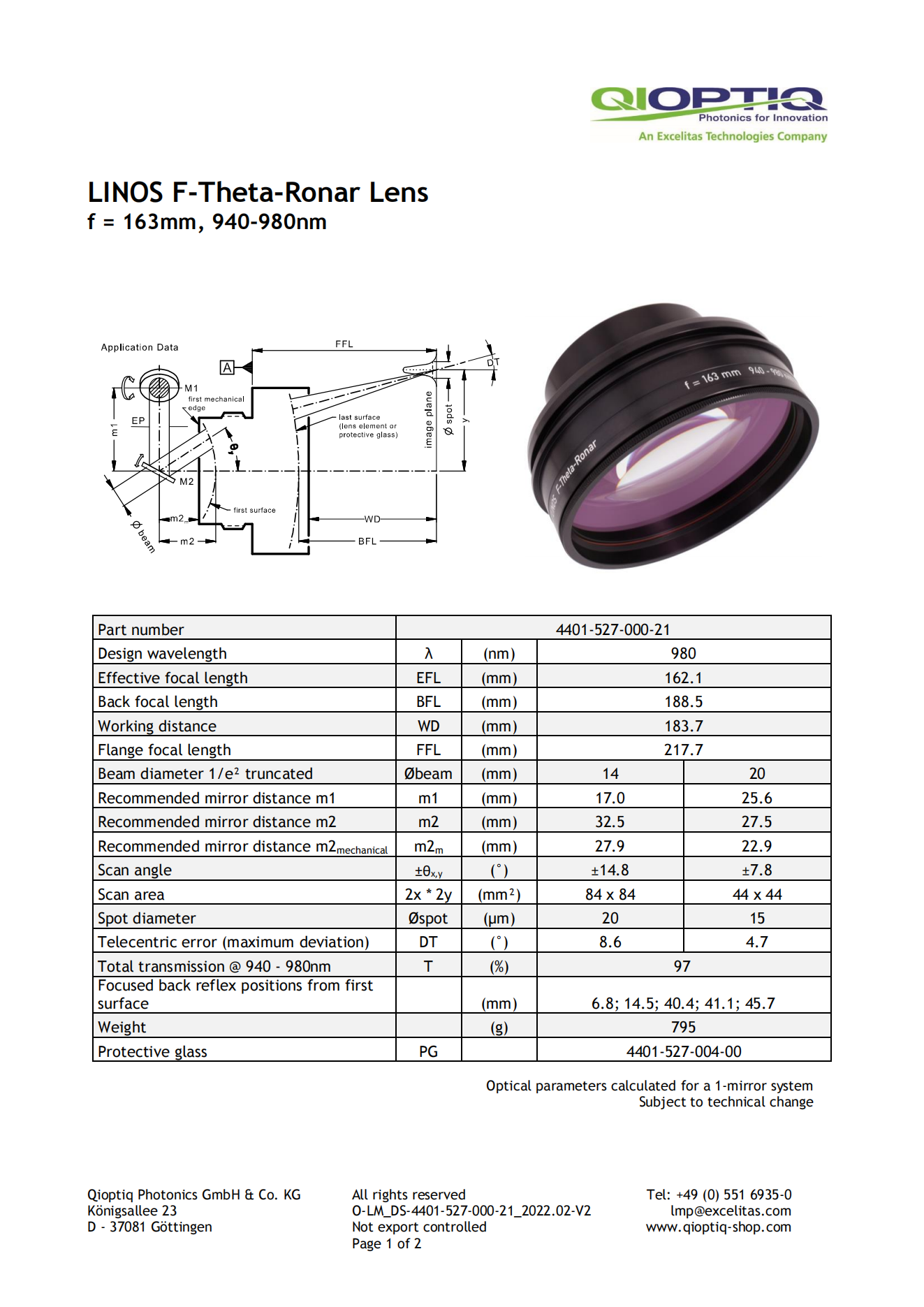
Take the LINOS 4401-527-000-21 F-Theta lens as an example: the same lens behaves completely differently at different entrance pupils:
| Entrance Pupil | Max Scan Angle | Actual Scan Field | Focused Spot |
|---|---|---|---|
| 14mm | ±14.8° | 84×84mm | 20μm |
| 20mm | ±7.8° | 44×44mm | 15μm |
| 16mm (derived) | ~±11° | ~60×60mm | ~17.7μm |
Pattern: larger entrance pupil → smaller allowed scan angle → smaller field → but a finer spot (because Φ₀=4M²λf/(πΦ): the larger Φ, the smaller the spot)
What does this mean? The nominal field is the maximum at a specific entrance pupil and scan angle; the actual field can be flexibly adjusted as needed!
Field technique 1—large field + short focal length: use a large-pupil lens (20/30mm entrance pupil) while the actual beam is only 10mm → larger galvo deflection angle → a field far beyond the nominal rating. For example, a lens rated 110×110 with a 30mm pupil may reach 180×180 when the actual beam is 10mm, and 150×150 when it is 20mm.
Field technique 2—small field + ultra-fine: take a 110×110 lens with a 20mm pupil, add a beam expander to fill the pupil → finer spot → shrink the field to 50×50 in software → fine and precise.
Scan Angle Matching
The scan angle of an F-Theta lens is an often-overlooked parameter. Common scan angle specs: ±11°, ±14.8°, ±15°, ±17.3°, ±20°, ±28°
Core principle: galvo deflection angle ≤ the F-Theta lens’s allowed scan angle. If the galvo cannot reach the lens’s maximum allowed angle, the actual field will be smaller than nominal. Conversely, when the lens entrance pupil is larger than the galvo aperture, the galvo can deflect at larger angles and the actual field exceeds the nominal value—exactly the pattern shown by the LINOS example above.
④ Path A Laser Systems—Focused Spot: Φ₀=4M²λf/(πΦ)
Theoretical formula for the focused spot diameter:
Φ₀=4M²λf/(πΦ)
where: f = focal length, λ = wavelength, Φ = incident beam diameter.
Example: a 1064nm fiber laser with a 7mm incident beam and laser M² = 1.5:
| Focal length f (mm) | Focused spot Φ₀ (μm) |
|---|---|
| F100 | ~29 |
| F160 | ~46.4 |
| F254 | ~73.7 |
| F330 | ~95.8 |
| F525 | ~152 |
⚠️ Important note: the values above are theoretical diffraction-limited values; the actual spot size must also account for the lens’s aberrations. Actual spots are typically 1.5–2× the theoretical value. Good manufacturers publish the actual spot size in their datasheets—pay attention to that figure when buying, not just the theory. In fact, the parameters in real F-Theta datasheets usually look better than the values in my table above. Why? First, lens manufacturers assume the beam-quality factor M² = 1, treating the laser beam as an ideal Gaussian beam, which makes their specs look better. Second, they generally compute from their own lens’s entrance pupil—for example, for a lens with a 12mm entrance pupil, they ignore that the actual fiber laser beam is 7±1mm, and they also ignore that most galvos in use have 10mm mirrors and cannot possibly reflect a 12mm beam into the lens. They calculate from their own entrance pupil because it makes the specs look better.
⑤ Working Distance WD ≠ Focal Length F!! The Deepest Pit
This is the most deeply misunderstood parameter in F-Theta selection. Many people assume working distance equals focal length—especially end users who see a focal length of F210 and simply measure 210mm straight down from the bottom edge of the lens. Dead wrong! That is not the focal length, it is not the focal length.
The F-Theta focal length is not the working distance—remember, remember: the working distance (WD) is the distance from the lower surface of the last lens element to the focal plane. The focal length (F) is the optical design value. The two differ, and not by a little! Generally, the smaller the field, the closer the F-Theta focal length is to the working distance; but the longer the focal length, the larger the gap—and the working distance is greater than the focal length
WD reference table for common F-Theta lenses:
| F-Theta Lens Model | Focal Length F (mm) | Working Distance WD (mm) | Recommended Column Height (mm) |
|---|---|---|---|
| F100 | 100 | ~100 | ~200 |
| F160 | 160 | ~185 | ~280 |
| F210 | 210 | ~245 | ~340 |
| F254 | 254 | ~298 | ~400 |
| F330 | 330 | ~385 | ~490 |
| F420 | 420 | ~492 | ~590 |
| F525 | 525 | ~597 | ~720 |
⚠️ Pitfall case: an integrator sized the marking machine column to the F525 focal length and used a 550mm column. After assembly, the focal point could not be found—the column was simply too low and could not rise high enough, so the focus was out of reach.
How to find focus—the continuous-emission method: during commissioning, first enable continuous marking in the marking software. Slowly turn the column hand crank so the column moves upward from its lowest position. When the marking sound becomes a sharp, forceful crackling, and then clearly loses force as you keep cranking upward, the position with the strongest sound is the focal height. At that moment, record the height from the bottom edge of the lens to the object being marked. From then on, whenever you mark objects of a different height, just set the distance from the lens bottom edge to the new object to the recorded value. Do not rely on theoretical values—actual measurement rules.
⑥ Depth of Focus: Make-or-Break for Curved Surfaces and Deep Engraving
Depth of focus (DOF) is the range before and after the focal point within which the spot diameter grows by no more than √2. The formula:
Depth of focus DOF= 2ZR=2πΦ₀²/M²λ
Depth of focus is proportional to the square of the focal length, so long-focal-length lenses have far deeper DOF than short ones:
| Focal Length | Focused Spot | DOF Range |
|---|---|---|
| F100 | ~28μm | ±2.3mm |
| F254 | ~72μm | ±15mm |
| F525 | ~148μm | ±64mm |
⚠️ Selection advice: for curved workpieces (e.g., marking on the side of a cylinder) or deep engraving (engraving depth > 2mm), a long-focal-length lens is mandatory. Short-focal-length lenses have only a few millimeters of DOF, and power density falls off a cliff with the slightest defocus.
⑦ Power Density Conversion: Equivalent Power Across Focal Lengths
Machining results depend on power density (W/mm²), not total power. Power density = power / spot area. Because spot size differs with focal length, the same laser power paired with different lenses yields vastly different power densities.
Conversion formula:
Equivalent power = actual power × (reference spot / actual spot)²
Example (1064nm, 12mm entrance pupil):
| Laser Power | With F110 Lens | With F254 Lens | With F525 Lens |
|---|---|---|---|
| 20W | Power density ≈25.8W/mm² | ≈3.9W/mm² | ≈0.92W/mm² |
| 50W | ≈64.5W/mm² | ≈9.8W/mm² | ≈2.3W/mm² |
| 100W | ≈129W/mm² | ≈19.6W/mm² | ≈4.6W/mm² |
⚠️ Key conclusion: the power density of 20W + F110 ≈ that of 71W + F525. So do not assume “a 100W laser unlocks a large field”—power density is king: at F525, 100W delivers less power density than 20W at F110.
⑧ Thread Interface: Awkward If It Will Not Fit
The mounting thread between the F-Theta lens and the galvo must match. Common specs:
| Thread Spec | Compatible Galvos | Typical Scenario |
|---|---|---|
| M39×1 | Cleaning-head galvos | Laser cleaning |
| M55×1 | Some RAYLASE galvos | Laser marking |
| M79×1 | Common marking galvos | Laser marking |
| M85×1 | Common marking galvos with an adapter ring | Laser marking |
| M95~112 | Large-aperture galvos | Laser welding |
| Screw-mounted | Custom/special | Some Han’s Laser machine models |
⚠️ Pitfall alert: you buy an M79-thread lens while the galvo is M85—it will not thread on! Confirm the galvo thread spec before purchasing, or buy a thread adapter ring.
⑨ Scan Angle and m1/m2 Values
Scan angle: the maximum incidence angle the lens accepts; commonly ±11°, ±14.8°, ±15°, ±17.3°, ±20°, ±25°. Scan angle and focal length together determine the final field—once the entrance pupil is fixed, the larger the scan angle, the larger the field (see the earlier discussion “the field is not a fixed value”).
⚠️ Pitfall alert: the galvo deflection angle must be ≤ the lens’s maximum allowed scan angle, or edge aberrations rise sharply and the spot deforms. The common complaint “a 110 lens only marks 80” may simply mean the galvo deflection angle is not large enough to reach the lens’s maximum scan angle.
m1/m2 galvo mirror positions: M1 and M2—especially m2—must be distinguished from the M² parameter. M1/M2 generally refer to the XY galvo mirrors; m1 is the spacing between the M1 and M2 mirrors (i.e., the distance between the X and Y mirrors), and m2 is the distance from the center surface of the first element of the F-Theta lens to the center of the M2 mirror.
Back reflection point: the position where light reflected inside the F-Theta lens returns behind the lens. A lens typically has several back reflection points, but the decisive one is that of the first surface. We must avoid letting any back reflection point of the lens land on a galvo mirror; otherwise, when laser power is high, the back-reflected light will focus right onto the mirror, damaging its coating or even shattering the mirror.
⚠️ Pitfall alert: with high-power lenses (>50W pulsed/>500W CW), poorly handled back reflections can burn out the galvo mirrors. Install strictly at the spacing required by the manufacturer.
4. Fiber Laser & F-Theta Lens Pairing Rating Table
This is the table many equipment builders need most—with different laser powers paired to different focal lengths, what actually works? Rating criteria:
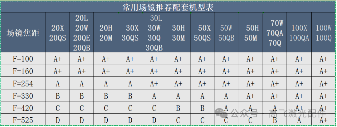
- A+: perfect match, ample power density, suitable for precision work
- A: good match, the first choice for general applications
- B: barely usable, compromises needed in some scenarios (e.g., lower speed, reduced precision)
- C: not recommended, noticeably degraded results
- D: severely mismatched, nearly unusable
5. Coaxial Vision Matching
For high-precision marking and cutting positioning, coaxial vision is nearly standard equipment. But coaxial matching is full of pitfalls, and many people step into them without ever knowing why.
Why Achromatic Correction?
Coaxial vision uses red light (650nm) as fill light, while the marking laser is 1064nm. Without an achromatic F-Theta lens, here comes the problem—glass refracts different wavelengths differently, so 1064nm and 650nm passing through the same lens do not focus at the same position!
How large is this focal shift? An ordinary lens may shift by 0.5–2mm—it sounds small, but for marking at 0.1mm precision it is a disaster. Then either the camera image looks clear while the mark comes out blurry and weak, or the mark is clear and strong while the camera image is a complete blur—visual matching becomes impossible, nothing looks sharp.
Achromatic Correction Targets Two Monochromatic Wavelengths, Not “Laser vs. Visible Light”!
⚠️ This is an extremely common misunderstanding. Many people think achromatic = correcting “laser and visible light.” It does not!
An achromatic F-Theta lens corrects chromatic aberration for two specific wavelengths, 1064nm and 650nm, so that the foci of the two wavelengths coincide. It is not broadband correction across “infrared and visible light,” but precise correction of these two monochromatic wavelengths.
Therefore:
- An achromatic lens only guarantees coincident foci at 1064nm and 650nm
- If you use 532nm green + 650nm red, an ordinary 1064+650 achromatic lens will not do the job
- When buying, always confirm that the achromatic wavelength pair matches your laser and indicator light
Fill Light Must Match the Wavelength
The camera in a coaxial vision setup needs fill light to see the workpiece clearly. The fill light wavelength must match the lens’s achromatic design—
⚠️ If the lens is achromatic for 1064+650, the fill light must be a 650nm red lamp—white light will not do!
Why? White light is broadband; after the lens, each wavelength focuses differently and the image blurs. A 650nm monochrome lamp paired with an achromatic lens gives a sharp, crisp image.
6. Thermal Lensing: The Hidden Killer at High Power
No matter how good the coating, an F-Theta lens never transmits 100%—there is always slight absorption. Absorption is typically 0.1%–0.5%, which looks negligible, but—
⚠️ 0.2% absorption under a 100W laser means 0.2W of heat continuously injected into the lens!
Heated, the lens’s refractive index changes and its curvature shifts slightly, moving the focal length—this is thermal lensing.
Symptoms:
- Normal for the first few minutes after startup, then focus gradually degrades
- Lines grow thicker after long emission
- Everything returns to normal after shutdown and cooling
Countermeasures:
- Below 50W: an ordinary lens is basically fine; temperature rise is manageable
- Above 50W: fused silica lenses are mandatory (thermal expansion far lower than ordinary glass)
- Above 200W: water-cooled lenses are mandatory (coolant circulates inside for heat dissipation)
- At every power level: choose high-quality lenses with coating absorption ≤0.15%
⚠️ Pitfall case: an integrator paired a 100W fiber laser with an ordinary-glass lens; five minutes after startup the focus had shifted 0.3mm and machining precision degraded from ±0.05mm to ±0.3mm—after switching to a fused-silica lens the problem vanished immediately.
7. Path A: Four Core Trade-offs and Solutions
F-Theta selection involves four core contradictions; only by understanding them can you make the right trade-offs.
Contradiction 1: Fine Spot ↔ Large Field
Shorter focal length → smaller spot → smaller field; longer focal length → larger field → larger spot.
Solution: use a 3D galvo (dynamic focus) plus an appropriately sized lens, keeping the field while achieving a small spot through Z-axis compensation. Or pair an XY stage with a short-focal-length lens, using stage motion instead of large galvo deflection. You can also exploit the dynamic pupil–field relationship—a large-pupil lens plus a small actual beam delivers a large field from a short focal length (see Chapter 3 ③ Entrance Pupil).
Contradiction 2: Precision ↔ Speed
High precision needs high expansion → large-mirror galvo → slower response; high speed needs low expansion → small-mirror galvo → larger focused spot → coarser line quality.
Solution: trade off by application. Choose high expansion when marking precision comes first; choose low expansion when on-the-fly speed comes first.
Contradiction 3: Expansion ↔ Depth of Focus
Higher expansion → smaller focused spot → shallower DOF. Shallow DOF means a tight focus tolerance—the slightest deviation defocuses the beam.
Solution: for applications that need DOF (curved surfaces, deep engraving), reduce the expansion ratio somewhat, trading a bit of spot fineness for a longer DOF.
Contradiction 4: Wavelength ↔ Depth of Focus
Short wavelengths (UV 355nm) → small spot → shallow DOF; long wavelengths (CO₂ 10600nm) → large spot → deep DOF.
Solution: when UV processing needs DOF, consider reducing the beam expander ratio or using a longer-focal-length lens. When CO₂ needs a small spot, consider a short-focal-length lens with high-ratio expansion. For extreme cases, combine UV with a 3D galvo.
Path B: F-Theta Lens Selection for Point-Source/Divergent-Beam Systems
If your laser emits divergent light (a point source)—typically a CW fiber laser with QBH/FC/SMA/D80 output—then the beam-expander route above does not apply at all! What you need is a collimator, not a beam expander.
Galvo welding, CW-fiber deep engraving, and similar applications all belong to this path.
8. Path B: F-Theta Lens Selection for Point-Source/Divergent-Beam Systems
Galvo welding is booming—new-energy batteries, 3C electronics, automotive parts, and medical devices all rely on it. The lens selection logic is completely different from marking! If you do welding, follow this chapter’s logic.
8.1 Beam Path Difference: Welding Must Collimate First
Marking lasers—Q-switched/MOPA—output parallel light and go straight into beam expander → galvo → F-Theta lens.
But galvo welding uses CW fiber lasers that output divergent light (a point source) through QBH/IQB interfaces—collimation first, no exceptions!
| System | Beam Path | Incident Light | Spot Formula |
|---|---|---|---|
| Marking system | Laser → beam expander → galvo → F-Theta lens | Parallel light | Φ₀ = 4M²λf/(πΦ) |
| Welding system | Laser → QBH → collimator → galvo → F-Theta lens | Point source/divergent light | d = (d_fiber × f_f) / f_c |
⚠️ Key difference: marking systems compute the spot from wavelength λ and incident beam diameter Φ; welding systems compute it from fiber core diameter d_fiber and the focal length ratio f_f/f_c. The two formula sets are completely different and must never be mixed!
8.2 Confirm 4 Parameters First
Before selecting a welding F-Theta lens, confirm the following 4 parameters:
- NA value — typically 0.11 for CW fiber lasers, 0.22 for some
- Fiber core diameter (d_fiber) — commonly 25μm, 50μm, 100μm
- Collimator focal length (f_c) — commonly 75mm, 100mm, 150mm
- F-Theta focal length (f_f) — commonly F160, F210, F254, F380, F420
8.3 Two Core Formulas
Collimated beam diameter: D = 2 × f_c × NA
Focused spot diameter: d = (d_fiber × f_f) / f_c
Note: the hierarchy in welding systems is F-Theta entrance pupil ≥ galvo aperture ≥ collimated beam diameter D. The entry quantity here is the collimated beam diameter D—not the marking system’s “output beam × expansion ratio”!
Selection order: compute D first → set the galvo aperture (≥D) → choose the lens entrance pupil (≥ galvo aperture) → pick the focal length based on spot size and welding thickness requirements
8.4 Worked Example
Assume: NA=0.11, fiber core diameter=50μm, collimator focal length=100mm
- D = 2×100×0.11 = 22mm
- Galvo aperture: choose 30mm (≥22mm)
- Lens entrance pupil ≥30mm
- Choose F160: d = (0.05×160)/100 = 80μm
- Choose F210: d = (0.05×210)/100 = 105μm
8.5 Balancing Focal Length, Spot, and DOF
- Focal length↑ → spot↑ → energy density spreads → but DOF↑ → needed for thick-plate welding
- Focal length↓ → spot↓ → energy density concentrates → but DOF↓ → thin plates only
- Choosing focal length is not just about spot size—also consider how thick the plate is! And whether the laser power is enough!
8.6 Common Welding Lens Questions
Q: Can a galvo welding lens and a marking lens be shared?
They can be shared! But welding lenses usually have larger threads—M95×1/M102×1/M112×1—different from the M85×1 or M79×1 of marking lenses, so you need a lens adapter ring.
Q: What if welding must cover different plate thicknesses?
Thin and thick plates need different focal lengths. Thin plates take short focal lengths (F160/F210) for a small, concentrated spot; thick plates take long focal lengths (F380/F420) for a longer DOF. If you must cover both, keep two lenses—it costs far less than swapping the laser.
9. Brand Recommendations
Imported Brands
- LINOS (Germany): high-precision F-Theta lenses, consistent quality
- SILL Optics (Germany): a dedicated F-Theta specialist with authoritative technical documentation
- JENOPTIK (Germany): high-end optical components with outstanding performance
Domestic Brands
- Wavelength Opto-Electronic (波长光电): well-standardized lens designs, strong value for money
- Tiankai Optoelectronics (Days凯光电) (Suzhou): complete F-Theta and galvo matching
10. Cost-Saving Selection Tips
Tip 1: Small-Mirror Galvo + Large-Pupil Lens
Use a short-focal-length lens to deliver a large field while keeping a small, precise spot—much cheaper than “high-power laser + long-focal-length lens.” For the principle, see Chapter 3 ③ Entrance Pupil, “dynamic relationship between entrance pupil and field.”
Tip 2: Keep Multiple Lenses on Hand
Short focal length for small products (high precision), long focal length for large products (large field), switching flexibly. More economical than buying one ultra-high-power machine.
Tip 3: Thread Adapter Rings
When the lens thread does not match the galvo, an adapter ring solves it—no need to replace either the galvo or the lens.
Tip 4: Exploit the Pupil–Field Dynamic Relationship
A large-pupil lens with a small actual beam → a field far beyond nominal; add a beam expander to fill the pupil → a finer spot. See Chapter 3 ③ Entrance Pupil.
11. Frequently Asked Questions (Q&A)
Q1: Why does my 110×110mm lens only mark 80×80mm?
Possible causes: ① galvo aperture > lens entrance pupil → switch to a larger-pupil lens ② galvo deflection angle < the lens’s allowed angle → use a galvo with a larger deflection angle ③ insufficient scan angle → see Chapter 3 ③ Entrance Pupil, “dynamic relationship between entrance pupil and field”
Q2: I want to mark 200×200mm—which focal length?
Focal length = 200 ÷ 0.7 ≈ 285mm; choose F290 or F330.
Q3: Is a large-field lens better, or a small-field one?
Bigger is not automatically better! Small fields give a small spot and high precision but shallow DOF (inconsistent results on curved parts); large fields give lower precision but longer DOF (consistent on curved parts). Choose by need, or keep several lenses.
Q4: Which lens for ultrafast lasers?
Fused silica is mandatory (high damage threshold); if distortion matters, choose a telecentric silica lens (distortion <0.1%), priced at roughly 3–5× an ordinary lens.
Q5: When is a telecentric lens needed?
Precision cutting/micromachining/machine vision/perpendicular hole drilling → yes. Ordinary marking → a standard lens is enough and more cost-effective.
Q6: The lens is rated 110×110—can I actually mark a larger area?
Yes! If the lens entrance pupil > the actual beam diameter, the galvo can deflect at larger angles and the actual field will exceed the rating. That is why a large lens with a 30mm pupil sometimes marks a bigger field—the actual beam entering the pupil is small, so the scan angle is not limited. See Chapter 3 ③ Entrance Pupil, “dynamic relationship between entrance pupil and field”.
12. 10-Point Checklist Before Buying a Lens
Before placing the order, verify the following 10 items one by one:
- ✅ Wavelength match: lens coating wavelength = laser wavelength; never mix
- ✅ Field is adequate: field ≥ maximum work size ×1.1, but not much larger
- ✅ Pupil is large enough: entrance pupil ≥ expanded beam diameter + 2–3mm margin
- ✅ Verify WD: confirm the actual working distance; do not rely on the focal length F value alone
- ✅ Power rating: lens rated power ≥ laser power ×1.2 (safety factor)
- ✅ Thread match: confirm the lens thread matches the galvo thread
- ✅ Spot size data: calculate the actual spot size; do not rely on theoretical values alone
- ✅ Coaxial vision: if coaxial vision is needed, choose an achromatic lens for the corresponding wavelengths
- ✅ Thermal lensing: fused silica above 50W, water cooling above 200W
- ✅ Supplier quality: do not blindly chase the lowest price—buy from major manufacturers and purchase lenses through knowledgeable specialists
13. Quick-Reference Selection Tables
Marking System Quick Reference
| Your Requirement | Recommended Focal Length | Recommended Entrance Pupil | Notes |
|---|---|---|---|
| Precision micromachining (electronic components, wafers) | F63~F100 | 10~12mm | Shallow DOF; the workpiece must be flat |
| Standard marking (metal nameplates, QR codes) | F160~F254 | 12~15mm | The most universal combination |
| Large-format marking (panels, keyboards) | F330~F420 | 15~20mm | Requires a high-power laser |
| Large-format welding (sheet metal, tubes) | F420~F525 | 20~30mm | Water-cooled lens mandatory |
| Curved-surface marking (cylinders, spheres) | F254~F330 | 15~20mm | Long focal length to preserve DOF |
| Deep engraving/3D relief | F254~F330 | 15~20mm | Even better with a 3D galvo |
| Coaxial vision positioning | Select by field | Select by beam path | Achromatic design + 650nm fill light mandatory |
| High-power welding (>200W CW) | F254~F525 | 20~30mm | Water-cooled lens + silica protective window |
Welding System Quick Reference
| Welding Scenario | Recommended Lens Focal Length | Typical Spot | Suitable Plate Thickness |
|---|---|---|---|
| Precision welding (ICs, thin sheets) | F160/F210 | 80~105μm | ≤1mm |
| Standard welding (3C housings, automotive parts) | F254/F300 | 120~150μm | 1~3mm |
| Thick-plate welding (structural parts, tube sheets) | F380/F420 | 190~210μm | ≥3mm |
Final Words
There is no “universal formula” for F-Theta selection. The core is to understand what each parameter means and how they contradict each other, then make the trade-offs your specific application demands.
Remember these iron rules:
- Marking system: laser output beam × expansion ≤ galvo aperture ≤ F-Theta entrance pupil; focused spot from Φ₀=4M²λf/(πΦ)
- Welding system: collimate before the galvo; focused spot from d=(d_fiber×f_f)/f_c; never mix the two formula sets!
- Field ≈ 0.7 × focal length, but WD ≠ focal length, and the field is not a fixed value (it depends on entrance pupil and scan angle)
- Power density is king, not total power
- Fused silica above 50W, water cooling above 200W
- Coaxial vision requires achromatic correction, and the fill light must match the wavelength
Choose the right lens and the machine’s performance improves immediately; choose wrong and even the most expensive laser is wasted. I hope this guide helps you choose right the first time and avoid detours.
If you still have questions during selection, contact the SOAR LASER technical team—we provide free F-Theta lens selection consulting.
📞 Technical hotline: 159-2722-0467
🌐 Website: www.soar-laser.cn
This article was originally written by the SOAR LASER technical team; please credit the source when republishing. Technical parameters are based on common industry practice—make the final selection against your actual working conditions.
Leave a Reply