


1. Definition of Terms: An ‘Inexpensive’ Optical Consumable that Matters Most
A laser protection window (Protective Window, also called protection window, protective lens, guard window or window plate) is a plane-parallel optical window with no optical power mounted at the very front of the output end of a laser processing head or optical system, or ahead of critical optical components. It is usually coated with an anti-reflection (AR) film for the working wavelength on both faces and, together with the O-ring in the holder, forms a sealed interface.
In the optical path it performs three functions at once:
- Transmit the laser — convey the main beam with the lowest loss, without focusing or changing its direction (a plane-parallel plate causes only a slight axial displacement and a focal shift);
- Block spatter and fumes — trap molten slag, spatter droplets, plasma fumes, oil mist and powder generated by processing on the window, protecting the costly focusing lens, collimator, f-theta lens and galvanometer behind it;
- Seal and isolate — form a gas-tight interface with the O-ring, maintaining protective-gas pressure and keeping dust and moisture out of the optical cavity.
Understanding a protection window takes one sentence: it is a sacrificial consumable, designed on the principle of ‘using a replaceable part costing tens of yuan to protect core optics worth thousands or tens of thousands’. The lower protection window nearest the sheet in a cutting head, and the window on a handheld welding head, are the most frequently replaced optical parts in the whole machine.
A widespread misconception needs correcting: a protection window is by no means exclusive to cutting and welding heads. Any location where the laser output faces contamination, spatter or a sealing requirement has one — fibre laser cutting heads (upper and lower windows), handheld and automated welding heads, beneath the f-theta lens on markers, the output of 3D dynamic focusing galvanometers, laser cleaning heads, CO₂ engravers and cutters, additive-manufacturing build chambers, laser cladding powder-feed heads, medical laser handpieces and research vacuum chambers; every station has its own specification and design logic.
2. Physical Principles and Optical Materials
2.1 Three optical effects of a plane-parallel window
A protection window is a flat plate with parallel faces (a plano-plano window) and has no optical power in itself, but once inserted into the optical path it still produces three effects that must be understood:
① Fresnel reflection loss. When light passes from air into a medium of refractive index n, part of it is reflected at each interface. Fused silica has n≈1.45 at 1064 nm, giving a single-surface reflectance of roughly:
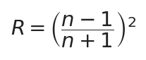
Single-surface reflectance at an air–glass interface, where n is the material’s refractive index; for fused silica n≈1.45 gives R≈3.5%
Uncoated, the two surfaces lose about 7% in total — on a 12 kW system that means over 800 W reflected or scattered, losing processing energy while creating return light and stray heat sources. With a multilayer AR coating the residual reflection per surface can be pushed below 0.25%, giving a total two-surface transmittance above 99.5%:
 Total transmittance of a plate window, with R₁ and R₂ the reflectances of the two faces; after dual-surface AR, T>99.5%
At high power, every percentage point of transmittance lost is real heat: on a 12 kW system 1% means 120 W absorbed or reflected by the window, enough to cause noticeable thermal lensing.
② Focal shift. Inserting a plane-parallel plate of thickness t and index n into a converging path moves the focus backwards along the axis (away from the plate) by:
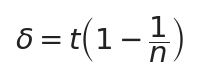
Focal shift caused by a plane-parallel plate; t is plate thickness, n is refractive index, fused silica n≈1.46
This means the thickness of a protection window is an optical design value, not something to increase for robustness: a 7 mm fused-silica window shifts focus by about 2.2 mm, so changing thickness arbitrarily changes the focus position of the whole machine. Windows beneath a marker’s f-theta lens are therefore made very thin (1–3 mm) and mounted as close to the lens as possible where the beam is still wide.
③ Plate aberrations and wedged windows. A plane-parallel plate introduces astigmatism at large incidence angles (edge beams in galvanometer scanning can exceed 20°); a window with strictly parallel faces also sends reflections from front and back surfaces back along the original path, forming Fabry–Pérot (F-P/etalon) interference fringes and ghost return light. Making the two faces meet at a small angle — a wedged window — deflects the back-surface reflection out of the path:
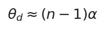
Beam deviation of a wedged window; α is the wedge angle, n the refractive index; a 30-arcminute wedge gives about 13 arcminutes of deviation
The most common standard wedge in industry is 30 arcminutes (about 0.5°), enough to break up interference and prevent return light feeding back into the laser; highly coherent or return-sensitive systems may use 1°–3°. Wedged plates must be installed in a strict orientation: reversing one sends the ghost reflection back along the original path into the laser and can cause return-light damage, so always follow the marks on the plate or holder.
2.2 Laser-induced damage threshold (LIDT)
LIDT (Laser-Induced Damage Threshold) is the critical fluence at which an optical component suffers irreversible damage (ablation, coating delamination, cracking, bulk damage) under specified laser conditions, tested according to the ISO 21254 series. Two operating regimes, two units:
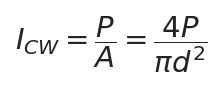
Average power density of a CW laser, in W/cm²; P is laser power, d is beam diameter at the window
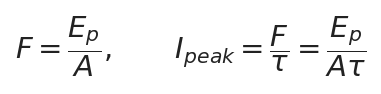
Pulsed fluence F (J/cm²) and peak power density (W/cm²); Eₚ is single-pulse energy, τ is pulse width
Three points must be borne in mind:
- LIDT varies sharply with wavelength and pulse width and cannot be transferred across conditions. The same fused-silica window has a threshold of about 15–30 J/cm² at 1064 nm / 10 ns, falling to about 5 J/cm² at 355 nm in the UV; shorter pulses (picosecond/femtosecond) mean higher peak power density and easier coating damage.
- The coating threshold is usually lower than the substrate’s. A premium bare fused-silica plate has a very high intrinsic threshold, but the absorption and defect density of the AR dielectric coating determine the usable threshold; deposition process and surface quality (scratches, pits) set the ceiling for LIDT.
- Contamination makes the effective threshold plummet. A single fingerprint or metal particle is a strong absorption site — test data from a clean window cannot save a contaminated one.
- All LIDT values in the table are measured on clean components under laboratory conditions and are not the power density allowed in the field. Real operating conditions require ample safety margin for wavelength, pulse width, spot size and contamination (often several times over in engineering); never take a manufacturer’s stated LIDT as the on-site operating limit.
Publicly available LIDT data for windows from major optics manufacturers (for order-of-magnitude reference in selection):
| Product / source | Stated LIDT | Test conditions |
|---|---|---|
| Edmund Optics 1064 nm V-coat fused-silica window | 15 J/cm² | 1064 nm, 20 ns |
| Mainstream optics manufacturers’ fibre-laser protection windows (typical) | about 20 J/cm² | 1030–1090 nm broadband (typical; refer to each maker’s data sheet) |
| Thorlabs Infrasil broadband AR window | 30 J/cm² | 1064 nm, 10 ns, 10 Hz |
| Thorlabs UV fused-silica window (-UV coating) | 5.0 J/cm² | 355 nm, 10 ns |
| Literature: clean bare fused silica (typical) | order of 20 J/cm² | 1064 nm, ns regime (varies with test conditions) |
| Literature: scratched/contaminated fused silica | markedly lower threshold (typical drop about one-third) | 1064 nm, ns regime (surface defects greatly reduce threshold) |
2.3 The full spectrum of protection-window materials
The first determinant of substrate choice is the working wavelength (a material’s transmission band is a physical boundary that coatings cannot overcome), followed by power/thermal load, contamination environment and cost. The following lists systematically all mainstream and specialty materials involved in laser protection windows, by material family.
(1) Fused silica family — the mainstay for fibre/UV/green lasers
The Chinese optical quartz glass grades JGS1/JGS2/JGS3 originate in the obsolete building-materials standard JC 185-81 ‘Optical Quartz Glass’ (revised as JC/T 185-1996; the current version is JC/T 185-2013 ‘Optical Quartz Glass’, which renames grades as ZS/HS/KS, though the JGS designations remain in industry use). The core differences among the three grades lie in hydroxyl (-OH) content and manufacturing process:
| Grade | Name / process | Transmission band | Hydroxyl content | Positioning |
|---|---|---|---|---|
| JGS1 | Far-UV optical quartz, SiCl₄ vapour synthesis (CVD / oxyhydrogen flame hydrolysis) | 185nm~2.5μm | High (about 1000–2000 ppm) | Highest purity, best deep-UV transmission and homogeneity; mainstay for high-power fibre/green/UV protection windows, corresponding to imported high-OH synthetic fused silica: Corning HPFS 7980 (OH 800–1000 ppm), Heraeus Suprasil 1/2, Saint-Gobain Spectrosil series |
| JGS2 | UV optical quartz, oxyhydrogen flame fused | 220nm~2.5μm | Medium (about 100–200 ppm) | Cost-effective tier, general purpose at medium-low power 1064 nm; has an OH absorption peak at 2.7 μm |
| JGS3 | IR optical quartz, vacuum electric melting | 260nm~3.5μm | Very low (almost no hydroxyl) | Good IR transmission, used above 2 μm and for IR optics; corresponds to imported low-OH electric-fused / IR-grade silica: Heraeus Infrasil series (natural crystal electric-fused), Corning 7979 (OH<1 ppm); note Infrasil is low-OH natural fused quartz and belongs to a different material family from high-OH synthetic JGS1 |
Fused silica’s core advantages are an extremely low thermal expansion coefficient (about 0.55×10⁻⁶/℃, roughly 1/13 that of K9 glass), excellent thermal-shock resistance (heated to 1100 ℃ and plunged into cold water without cracking), broad high transmission from deep UV to near IR, and Mohs hardness 7 for scratch resistance. This is why high-power fibre laser protection windows are almost universally fused silica (preferably JGS1).
The practical boundary of hydroxyl absorption needs clarification: -OH has a strong absorption peak at 2.7 μm (about 2600–2800 nm), while 1064 nm fibre lasers, 532 nm green and 355 nm UV are completely unaffected by hydroxyl; hydroxyl mainly reduces transmission above 2 μm in the IR — hence high-OH JGS1 is actually the first choice for fibre/green/UV windows, and only above 2 μm is a low-OH material such as JGS3 needed.
(2) Optical glass — cost-effective for low power and large sizes
| Material | Transmission band | Characteristics | Window positioning |
|---|---|---|---|
| K9 / H-K9L (Chinese, equivalent to Schott N-BK7) | approx. 350 nm–2 μm | Low cost, easy to machine, good homogeneity; expansion about 7.1×10⁻⁶/℃, poor thermal-shock resistance | Low-power (<500 W) marking/alignment/f-theta protection windows, an economical option costing tens of yuan |
| Schott N-BK7 | approx. 350 nm–2.1 μm | German Schott crown glass, better batch stability and homogeneity than ordinary K9 | Spare parts for imported equipment, precision low-power systems |
| Schott Borofloat 33 borosilicate float glass | approx. 350 nm–2.5 μm | Expansion about 3.3×10⁻⁶/℃ (between K9 and silica); float process enables large thin sheets at far lower cost than silica | Cost-effective option for medium-large f-theta/galvanometer protection windows, medium-low power |
| Schott B270 / D263T | approx. 300 nm–2.5 μm | Ultra-white crown / ultra-thin borosilicate (down to 0.1 mm) | Low power, ultra-thin windows |
(3) Sapphire and specialty hard materials — upgrades for extreme conditions
Sapphire (single-crystal Al₂O₃) transmits about 0.15–5.5 μm, has Mohs hardness 9 (second only to diamond), a melting point around 2050 ℃, excellent chemical stability and far greater resistance to spatter-particle erosion than silica. Its drawbacks are high cost (several times silica) and the need to cut single-crystal material oriented to the optical axis because of birefringence. Its role in protection windows is an upgrade for severely contaminated conditions — laser cladding powder-feed heads, laser cleaning, heavy-spatter cutting of highly reflective materials (copper/aluminium/galvanised sheet), and long unattended stations; mainstream fibre cutting/welding windows remain fused silica. In addition CVD diamond (transmits about 0.23–25 μm, extremely high thermal conductivity, the highest LIDT) represents the frontier for ultra-high-power windows, at very high cost and currently limited to extreme research and defence applications; transparent spinel (MgAl₂O₄) can make large, hard polycrystalline windows.
(4) The CO₂ and IR material family — 10.6 μm is a different world
Fused silica and K9 absorb strongly at 10.6 μm and must never be used for CO₂ lasers. CO₂ wavelengths require IR materials:
| Material | Transmission band | Characteristics | Window positioning |
|---|---|---|---|
| ZnSe (zinc selenide) | approx. 0.5–22 μm | High transmission at 10.6 μm, uniform refractive index, non-hygroscopic; relatively soft and scratch-prone (Knoop hardness about 110); cutting/polishing dust is hazardous and handling and breakage disposal require proper protection | The absolute mainstay for CO₂ windows and focusing lenses, grown by CVD |
| GaAs (gallium arsenide) | approx. 1–15 μm | Hard, strong, non-hygroscopic, reasonably conductive; opaque to visible light | Alternative for high-power CO₂ windows |
| ZnS (zinc sulfide) | approx. 0.4–12 μm (wider for multispectral grades) | Harder than ZnSe, impact-resistant, multispectral transmission | IR windows, multiband systems |
| Ge (germanium) | approx. 2–14 μm | High refractive index (about 4.0); absorption rises sharply with temperature (thermal runaway), opaque to visible light | Used in CO₂/IR systems mainly for thermal imaging, pyrometry and low-power windows; germanium windows are rarely used for high-power transmission because of thermal-runaway risk |
| Si (silicon) | approx. 1.2–8 μm | Very high thermal conductivity (about 150 W/(m·K)), inexpensive, opaque to visible light; a strong absorption band at 9 μm | 3–5 μm mid-IR windows/filter substrates; ordinary Czochralski (CZ) silicon has an oxygen absorption band at 9 μm and is unsuitable for 10.6 μm transmission; float-zone (FZ) high-purity lightly doped silicon with a dedicated IR AR coating can transmit 10.6 μm, but under high-power CW CO₂ heating induces free-carrier absorption with thermal-runaway risk, so industrial CO₂ transmission windows use ZnSe/GaAs — in CO₂ equipment silicon is used mainly as gold-coated mirror substrates rather than protection windows |
(5) Fluorides and UV materials: CaF₂ (about 0.13–10 μm, deep-UV/excimer/ultrafast windows, low index, nearly insoluble in water but vulnerable to knocks), MgF₂ (about 0.11–8.5 μm, the hardest fluoride, moisture- and radiation-resistant, deep/vacuum UV), BaF₂ (about 0.15–12 μm, slightly water-soluble, needs a dry environment), LiF (about 0.105–7 μm, the limiting material for vacuum-UV transmission, soft). Fluoride crystals mainly serve deep UV (below 355 nm), excimer (193/248 nm) and broadband research, and are rarely seen in industrial processing heads.
Material selection in brief: 1064 nm fibre/YAG → JGS1 fused silica (sapphire for harsh conditions); 532 nm green / 355 nm UV → JGS1 plus wavelength-specific coating (CaF₂/MgF₂ for deep UV); 10.6 μm CO₂ → ZnSe (GaAs for high power); visible/low-power marking → K9/Borofloat 33; above 2 μm IR → JGS3/sapphire; extreme ultra-high power → CVD diamond.
2.4 Anti-reflection coatings and coating selection
Protection windows are AR-coated on both faces; common coating types:
- Single-layer MgF₂ coating: residual reflection about 1.5% per face, economical for low power;
- Narrowband V-coat: reflectance <0.25% at a single design wavelength, the mainstream choice for 1064 nm fibre lasers;
- Broadband AR (BBAR): covering e.g. 1030–1090 nm or 900–1100 nm, suiting multiple machine types and femtosecond broadband sources;
- Dual-/multi-wavelength coating: optimising 1064 nm plus red alignment (635/650 nm), or 1064+532+355 nm harmonic coaxial systems;
- Low-absorption AR coating: for ten-kilowatt-class high power, where coating absorption matters more than reflectance and a low-absorption film suppresses thermal-lens focal drift;
- DLC diamond-like hard coating: improves wipe and spatter resistance for harsh conditions.
3. Structural Classification: Windows for Six Stations
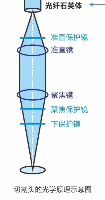
Figure 1. Optical principle of a fibre laser cutting head: the laser emerges from the fibre and passes in order through the upper protection window (collimator side), collimator, focusing lens and lower protection window (focusing side; some machines have a separate focus-protection window) — the number of window stations varies by manufacturer, refer to the maker’s manual
Source: Anno Optical (technical data on laser cutting head optics)
3.1 Cutting-head protection windows (upper + lower)
A typical fibre cutting-head optical path: laser output head → upper protection window → collimator group → focusing group → lower protection window → nozzle → sheet.
- Lower protection window: located below the focusing lens and above the nozzle, facing molten-pool spatter and piercing slag directly; it is the most frequently replaced lens in the whole machine. Its aperture is usually larger and its thickness greater than the upper window (to withstand more contamination and thermal shock).
- Upper protection window: located above the collimator, near the fibre output end, it intercepts dust entering the cavity during consumable changes and fumes flowing back upwards, protecting the collimator and laser output head. It is less contaminated and replaced less often.
- The upper and lower windows often differ in size, thickness and coating and are not interchangeable. Taking the RayTools BT240S cutting head manual as an example: upper window D24.9×1.5 mm (manual part number 211LCG0020), lower window D27.9×4.1 mm (part number 211LCG0037); a dual-drawer window structure with seals provides IP65 protection.
Common circulation sizes for cutting heads (industry-standard imperial/metric size families; refer to the machine specification): D24.9×1.5, D27.9×4.1 (1.1″×0.16″), D30×5, D34×5, D37×7, D38.1×1.6 (1.5″), D50×2/3 and so on. The higher the power, the larger the aperture and thickness: 6–12 kW commonly uses D37×7; ten-kilowatt class uses larger apertures with low-absorption coatings.
3.2 Welding-head protection windows (including handheld)
Welding contamination differs from cutting: molten-pool droplets adhere strongly, welding fumes contain oil mist, and a handheld torch sits close to the pool with weak air-knife protection — handheld welding windows are among the most frequently replaced, with the common complaint of ‘only remembering to change the lens when no light comes out’. Sizes are mostly small-diameter: D18×2, D20×2, D20×3, D21.5×2, D27.9×4.1 and so on (the WSX official protection-window series covers 18×2, 20×2, 20×3, 21.5×2, 22.35×4). Automated/oscillation/remote welding heads use larger apertures, and high-power models use water-cooled holders. Material is mainly JGS1 fused silica, with sapphire an option for extremely heavy spatter.
3.3 F-theta protection windows (marking/engraving systems)
Galvanometer marker optical path: laser → beam expander → XY galvanometer → F-theta lens → protection window → workpiece. Marking power is usually only tens of watts, but organic volatiles from marking plastics and resins (tar-like oil mist) and metal-marking fumes deposit upwards onto the lowest surface of the f-theta lens — an f-theta lens is a precision group of 3–6 elements whose internal contamination can hardly be cleaned on site and costs thousands to replace. Adding a thin protection window (1–3 mm thick, K9 or JGS1) below the lens, spending tens of yuan to save a lens costing thousands, is the most cost-effective protective modification for marking equipment. Note that the f-theta window sits in the converging path behind the lens, so its thickness shifts focus by δ=t(1−1/n): a thin specification must be used and the mounting position kept consistent.
3.4 Dynamic galvanometer / 3D scanner protection windows
3D dynamic focusing galvanometers (e.g. large-format marking and welding scanners) have large-aperture output windows (Ø40–100 mm), and edge-of-scan beams arrive at large angles (over 20°), requiring high surface figure (λ/10 or better), low stress birefringence, dual-side broadband AR coatings and no vignetting across a wide field. Material is mainly JGS1/synthetic fused silica; for large, medium-low power applications Borofloat 33 can control cost. An isolation sealing window is also often found at the galvanometer-box entrance (laser side).
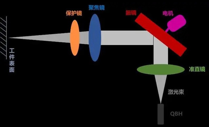
Figure 2. Optical path of a galvanometer laser processing head: QBH output → collimator → galvanometer deflection → focusing lens → protection window → workpiece, with the window at the output end nearest the workpiece
Source: Technical data on galvanometer laser processing head optics
3.5 Laser cleaning head protection windows
Cleaning heads shine directly on rust, paint and oil, with the highest back-spray dust load of all; the window is usually changed every shift, supported by a quick-change drawer and air knife. Material is mainly JGS1 (K9 for some economical types), with sapphire extending life in extremely contaminated conditions.
3.6 CO₂ systems and other stations
- CO₂ marking/cutting/engraving: the window must be ZnSe (or GaAs), an entirely different material family from fibre lasers;
- Additive manufacturing (SLM/SLS): build-chamber sealing window isolating metal powder and inert gas, fused silica/K9/sapphire;
- Laser cladding / powder-feed heads: powder erosion plus spatter, where sapphire windows have a clear life advantage;
- Medical lasers: hygienic isolation window at the handpiece, requiring sterilisation and biocompatibility, fused silica/sapphire/CaF₂;
- Research/vacuum/excimer: vacuum and gas-isolation windows, choosing JGS1/CaF₂/MgF₂/LiF by wavelength.
4. Key Parameters and Selection Tables
4.1 Wavelength–substrate correspondence table
| Laser type | Wavelength | Substrate | Coating |
|---|---|---|---|
| Fibre laser | 1064~1080nm | JGS1 (silica mandatory above 500 W) | 1064 narrowband V-coat or 1030–1090 broadband |
| Green / UV | 532/355nm | JGS1 (CaF₂/MgF₂ for deep UV) | Wavelength-specific coating; LIDT drops markedly, leave margin |
| CO₂ laser | 10.6μm | ZnSe (GaAs for high power) | 10.6 μm dedicated AR |
| Diode blue | 450nm | JGS1/K9 | 450nm AR |
| Femtosecond ultrafast | 1030 ± tens of nm | Synthetic fused silica (low fluorescence) | Broadband AR, watch GDD and fluorescence |
| Low-power marking/alignment | Visible–1064 nm | K9/BK7/Borofloat 33 | Standard AR |
4.2 Power–thickness–coating tiers (fibre cutting head, empirical)
| Power tier | Substrate | Common thickness (typical empirical values) | Coating |
|---|---|---|---|
| <500W | JGS1/K9/Borofloat | 1~3mm | Standard AR |
| 0.5~3kW | JGS1 | 1.5~4mm | Multilayer AR |
| 3~6kW | JGS1 | 4~5mm | Low-absorption AR |
| 6~12kW | JGS1 (large aperture) | 5~7mm | Low-absorption high-threshold AR |
| >12kW | JGS1 large aperture / sapphire | 7mm+ | Ultra-high-threshold coating, confirm with manufacturer |
4.3 Other key parameters
- Diameter × thickness (D×T): mechanical mounting dimensions; diameter tolerance is typically on the order of ±0.05 mm — a 0.1 mm difference may prevent a seal or prevent fitting; check step/chamfer features too. Measure the old part with callipers before ordering.
- Transmittance: a quality dual-side AR plate exceeds 99.5% total transmittance; rely on the factory test report, and re-measure piece by piece at high power where practical.
- Surface quality (scratch-dig): specified to MIL-PRF-13830B/ISO 10110; common grades 40-20 (general industrial), 20-10 (premium high power), 10-5 (research/ultra-high power); lower numbers mean fewer surface defects and higher LIDT.
- Surface figure / parallelism: λ/4 @633 nm suffices for an ordinary window; f-theta/dynamic galvanometer windows require λ/10–λ/20 with parallelism <1 arcminute; wedged windows state the wedge angle (commonly 30 arcminutes).
- Power-density check: the beam at the window is collimated or weakly converging (a few millimetres to 20 mm across), so power density is far below that at the focus. For example, at 6 kW with an Ø8 mm beam at the window the average power density is about 12 kW/cm²; pulsed conditions must be checked by peak power density.

Worked example: 6 kW fibre laser with an Ø8 mm beam at the window gives about 12 kW/cm² average power density (note: use the actual beam size in the path — the focal spot size must not be used for the window check)
5. Characteristics, Advantages and Limits of Use
Advantages: extremely low cost (tens to hundreds of yuan versus thousands to tens of thousands for a focusing lens or f-theta lens); quick replacement (drawer or retaining-ring construction, minute-level); loss under 0.5% with dual-side AR, negligible for the optical path; a sealed cavity maintains protective gas and cleanliness.
Boundaries and limitations:
- A protection window is a plane-parallel plate with no focusing or collimating function and cannot replace any lens;
- Changing thickness moves the focus (δ=t(1−1/n)), so replace to the original specification and never thicken arbitrarily;
- A plane plate introduces astigmatism in a steeply converging path, so f-theta/galvanometer windows need thin, high-figure plates;
- It is contamination-sensitive — LIDT data apply only to a clean surface and the threshold drops off a cliff once contaminated;
- Materials have strict wavelength boundaries: ZnSe for CO₂, silica for fibre, cross-family misuse causes immediate cracking or opacity;
- Failure is sudden: at high power, going from ‘slightly contaminated’ to ‘cracked’ may take only seconds.
5.1 How contamination ‘kills’ a window
The physical chain of cracking: spattered droplets/oil film/fume deposit → local strong absorption sites → laser energy converted to heat at those points → local temperature spikes and coating ablation → further absorption at the damaged area (positive feedback/thermal runaway) → thermal stress exceeds material strength → microcracks and catastrophic shattering (‘window explosion’) → fragments and heat may reach the focusing lens. Meanwhile uneven contamination produces a thermal lens effect, slowly shifting focus and deforming the spot, showing up as dross, incomplete cuts and shallower marks — quality degradation usually precedes visible damage.
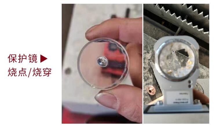
Figure 3. Two-stage photo of window failure: left, a central burn spot (localised raised melt point, an early-warning sign); right, complete burn-through (large-area melted loss, already endangering the focusing lens)
Source: Raycus Laser (technical data on window burn spots and burn-through failures)
6. Typical Applications and Selection Advice
6.1 Six-step selection process
- Define the station: cutting head (upper/lower?), welding head (handheld/automated?), f-theta, dynamic galvanometer, cleaning head, CO₂ or other — determines the size family, thickness and contamination level;
- Define the wavelength: 1064/532/355/10.6 μm/450 nm — determines substrate and coating; materials cannot be interchanged across wavelength families;
- Define the power: choose substrate tier, thickness and coating with margin at the actual maximum power (fibre above 500 W requires JGS1 silica);
- Define the size: measure the old part’s diameter, thickness, step and chamfer with callipers, and confirm whether the holder has a locating step or slot (checking only D×T while ignoring the step causes assembly interference or a failed seal), then verify against the machine specification (diameter tolerance ±0.05 mm);
- Define the precision: 40-20 for ordinary cutting/welding; 20-10 for high power; λ/10 high figure for f-theta/galvanometer windows; choose a 30-arcminute wedged plate for return-sensitive systems and mind the orientation;
- Define supply and spares: prefer the original manufacturer or a trusted channel, request LIDT test conditions and inspection reports; hold safety stock by duty cycle (handheld welding, cleaning and highly reflective material cutting consume windows per shift).
6.2 Mainstream equipment compatibility (refer to manufacturer specifications)
| Brand / equipment | Publicly available specification examples | Notes |
|---|---|---|
| RayTools BT240S cutting head | Upper D24.9×1.5 (official part 211LCG0020), lower D27.9×4.1 (part 211LCG0037) | BM series also has 37×7, 38.1×1.6 and others; refer to the machine manual |
| Precitec | ProCutter and other series with D37×7 and similar | German specification system, original-manufacturer channel recommended |
| WSX | Official series include 18×2, 20×2, 20×3, 21.5×2, 22.35×4, 30×5 and others | 18×2 most common for handheld welding; 30×5/37×7 for cutting heads |
| BOCI / Ospri / Han’s Laser / Hongshan and others | Varies by machine model | Report the full model to verify against the specification |
| F-theta/galvanometer (Scanlab, Ronar-Smith, Sill and others) | Protection windows mostly optional, following the f-theta aperture | Some f-theta barrels accept add-on windows at the lower end; thin, high-figure types |
⚠ Ordering red line: a 0.1 mm size error can prevent sealing, cause leaks, crack the window or prevent fitting; always measure the old window with callipers and confirm diameter, thickness, step structure and coating wavelength against the specification, distinguishing upper from lower windows. All sizes listed are examples of industry-circulation size families and do not constitute parameters for any specific model.
6.3 Installation, cleaning and replacement SOP
Replacement procedure: power down and cool → unscrew the retaining ring or pull out the drawer → remove the old window and inspect the O-ring → handle the new window only by its edge, wearing finger cots, never touching the optical faces → confirm orientation (wedged or single-side-coated plates follow their marks) → seat the O-ring and tighten diagonally and evenly to a moderate torque (over-tightening cracks the plate) → test at low power for 30 seconds → raise to working power.
Cleaning (only for light loose dust): ① first blow off loose dust with clean nitrogen or compressed air, never dry-wipe; ② use a lint-free lens tissue or optical swab dipped in optical-grade anhydrous ethanol (or an ethanol-acetone mix as the coating supplier advises), wiping gently in one direction from centre to edge, a fresh face each time, never scrubbing back and forth; ③ inspect against light for fibres, water marks and fingerprints. Ablation spots, coating delamination and ring stains cannot be cleaned and require replacement. ZnSe is soft and its dust toxic: no dry wiping, and dispose of breakage properly.
O-ring: inspect at every window change; replace if flattened, cut or aged (recommend changing the O-ring every 3–5 windows); a failed seal means fumes go straight into the lens cavity.
Replacement interval (empirical guide, governed by inspection and processing quality): high-contamination scenes such as handheld welding and laser cleaning — check each shift, on the order of 8–50 hours; 3–12 kW cutting — check each shift, 30–100 hours; marking f-theta/galvanometer windows are lightly contaminated — check monthly, hundreds to thousands of hours; cutting copper/aluminium reflective materials and thick-plate piercing shorten this markedly. The principle is preventive replacement: waiting for a ‘bang’ usually costs the focusing lens as well.
7. Common Misconceptions
| Misconception | Fact |
|---|---|
| ‘The thicker the protection window, the more durable it is’ | Thickness is an optical design value: a thick plate shifts focus back by δ=t(1−1/n) (about 2.2 mm for a 7 mm plate) and increases thermal inertia. Replace to the original specification — changing thickness arbitrarily means re-focusing the whole machine. |
| ‘Protection windows are only used in cutting/welding heads’ | Windows exist beneath f-theta lenses, at 3D galvanometer outputs, in cleaning heads, SLM build chambers, cladding powder-feed heads, medical handpieces and CO₂ equipment — only the specifications and materials differ. Adding a tens-of-yuan window under a marker to save a thousands-of-yuan f-theta lens is excellent value. |
| ‘All fused silica is the same — buy the cheapest’ | JGS1/JGS2/JGS3 differ completely in hydroxyl content, purity and process; low-cost plates may be passed off as JGS1 using JGS2 or even recycled material, with coating, parallelism and surface quality cut correspondingly, multiplying the cracking risk at high power. |
| ‘A CO₂ machine can use a silica window’ / ‘a fibre machine can use a silicon plate’ | Fused silica absorbs strongly at 10.6 μm and silicon has a strong absorption band at 9 μm and is opaque at 1064 nm — a material’s transmission band is a physical boundary; cross-family misuse either blocks the beam or cracks the plate. CO₂ transmission windows use ZnSe/GaAs; in CO₂ equipment silicon is used mainly for gold-coated mirrors. |
| ‘Replace it only when it breaks; keep using it while it works’ | Contamination is progressive and irreversible, and focal drift from thermal lensing precedes visible damage; at high power, going from slight contamination to cracking may take only seconds. Preventive replacement is consumable management; replacing only on failure is gambling with the focusing lens. |
| ‘K9 and silica are much the same — save where you can’ | K9 expands about 13 times as much as silica and has poor thermal-shock resistance; above 500 W CW, K9 must never substitute for fused silica. But using K9/Borofloat for low-power marking/f-theta windows is reasonable cost-saving. |
| ‘The coating doesn’t matter, as long as light gets through’ | Uncoated, the two faces reflect about 7%, nearly 800 W lost on a 12 kW system plus return light; the coating also sets the LIDT ceiling. Wrong-wavelength and poor-quality coatings are the main causes of early failure and heating. |
| ‘If it’s dirty, just wipe it and carry on’ | Only light loose dust can be cleaned properly; ablation spots, delamination and ingrained oil cannot be cleaned, and wiping only spreads coating damage. |
| ‘Dry wiping, a spectacles cloth or breathing on it are all fine’ | Dry wiping grinds dust into the coating; ordinary fabrics contain hard particles; breath and saliva contaminate the film. Nitrogen blow plus a one-direction wipe with optical consumables is mandatory. |
| ‘A few tenths of a millimetre off the size doesn’t matter’ | Diameter tolerance is on the order of ±0.05 mm; a 0.1 mm deviation can cause leaks, cracking or a failure to fit; a mismatched step or chamfer also breaks the seal. |
| ‘If the window cracked it must be a quality problem’ | Troubleshoot in this order: wedged plate installed backwards → O-ring leak admitting dust → cleaning residue/fingerprint → over-power or wavelength mismatch → only then the window itself. Most ‘quality problems’ are actually installation and maintenance problems. |
| ‘The upper protection window is optional’ | The upper window protects the collimator and fibre output head (ten-thousand-yuan class), making a tens-of-yuan window the best insurance; a dual-window design is standard in high-power cutting heads. Note that some compact low-power cutting heads have no provision for an upper window and cannot be retrofitted in hardware; follow the specific machine structure rather than forcing a modification. |
| ‘Protection windows are interchangeable across all machines’ | Cutting, welding, f-theta, galvanometer, cleaning and CO₂ stations each have their own aperture, thickness, material, coating and wedge-angle system; borrowing across machine models inevitably goes wrong. |
| ‘Sapphire is always better than silica’ | Sapphire has excellent hardness and erosion resistance but costs several times more, needs orientation for birefringence, and silica is already sufficient for ordinary cutting and welding; it is an upgrade for heavy-contamination stations such as cladding, cleaning and reflective materials, not a universal improvement. |
8. History and Development Trends
The protection window emerged as a distinct consumable category alongside the spread of high-power industrial lasers. Early sub-kilowatt laser processing usually relied on a single focusing lens directly facing the work zone, and a contaminated lens was scrapped; as fibre laser power leapt from kilowatts to tens of kilowatts and cutting heads adopted a modular collimate-focus separated structure, the ‘upper + lower window’ dual-window seal became standard in high-power cutting heads (e.g. the RayTools BT240S IP65 dual-window structure), and the protection window became the most-consumed optical part among laser processing consumables.
Current trends: ①ten-kilowatt-class drives coating upgrades — low-absorption AR and high-threshold coatings are standard at high power, and coating-absorption thermal lensing is the main source of focal drift in ten-kilowatt cutting; ②intelligent condition monitoring — some cutting heads integrate contamination monitoring (real-time transmission/scattering alarms), moving from ‘scheduled replacement’ to ‘on-demand replacement’; ③material frontiers — CVD diamond windows explore ultra-high-power applications with extreme conductivity and damage thresholds, while sapphire penetration grows in heavy-contamination stations; ④greater protection awareness in marking/galvanometer scenarios — f-theta protection windows are moving from optional retrofit to an original-equipment option.
9. References
- RP Photonics Encyclopedia — Fused Silica, Laser-induced Damage, Anti-reflection Coatings, Wedge Prisms: rp-photonics.com
- ISO 21254 series — Lasers and laser-related equipment — Test methods for laser-induced damage threshold (international standard for LIDT testing)
- JC/T 185-2013 ‘Optical Quartz Glass’ (current building-materials industry standard, replacing the abolished JC 185-81; the JGS1/JGS2/JGS3 designations originate in the 1981 edition and remain in use: far-UV 185–2500 nm / UV 220–2500 nm / IR 260–3500 nm)
- RayTools BT240S 3 kW/3.3 kW cutting head user manual (Shanghai RayTools Automation; spare-parts appendix: protection window D24.9×1.5-4K/1064 nm part 211LCG0020, D27.9×4.1-4K/1064 nm part 211LCG0037, dual-drawer window structure): BT240S user manual PDF | ManualsLib online manual
- Thorlabs — Silicon Windows technical document (‘silicon has a strong absorption band at 9 μm and is unsuitable for CO₂ laser transmission’): thorlabs.com
- Edmund Optics / Newport / Thorlabs — published LIDT data for laser windows and AR coating application notes
- SCHOTT — N-BK7, Borofloat 33, B270 optical glass data sheets: schott.com
- Corning HPFS 7980 (high-OH synthetic) / Corning 7979 (low-OH IR grade) / Heraeus Suprasil (synthetic), Infrasil (natural crystal electric-fused) fused silica grade material data
- WSX official laser protection window product specifications: wsxlaser.com
- Chinese Journal of Laser / Acta Optica related literature — experimental studies of the effect of surface scratches on the laser damage threshold of fused silica
📚 Further reading
- F-theta lens encyclopedia: principles and selection of marker f-theta lenses
- Achromatic f-theta lens encyclopedia: dual-wavelength confocal and coaxial-vision lens selection
- Laser beam expander encyclopedia: principles, classification, selection and misconceptions
- Laser collimator encyclopedia: industrial collimation systems and interface selection
🔧 Related Product Recommendations
Changsha Soar Laser supplies the full range of fibre laser cutting/welding protection windows (JGS1 fused silica, dual-side AR at 1064 nm, in all sizes D24.9×1.5, D27.9×4.1, D30×5, D34×5, D37×7, D18×2 handheld welding and more), f-theta/galvanometer windows and CO₂ ZnSe windows, compatible with RayTools, Precitec, WSX, BOCI and other mainstream cutting/welding heads. For selection please provide the machine model, laser wavelength, power and measured dimensions of the old part; contact the hotline 15927220467.
Leave a Reply