


Laser Beam Expander
A laser beam expander is an afocal optical system based on the telescope principle, used to change the diameter and divergence angle of a collimated laser beam. Its core function is to convert a collimated laser with a small diameter and large divergence angle into one with a larger diameter and smaller divergence angle (or used in reverse to reduce the beam). Beam expanders are widely used in laser processing, laser measurement, interferometry and research, and are the key element connecting the laser to downstream optics (galvos, scan lenses, focusing lenses) in a laser path.
Based on the RP Photonics Encyclopedia as the theoretical standard and combined with Soar Laser technical team’s years of industrial selection experience, this article systematically covers the physical principles, optical structures, key parameters, selection methods and common misconceptions of laser beam expanders, reaching technical selection-level depth.
==================== Chapter 1 Terminology ====================
I. Terminology and Definitions
1.1 Basic Definition
A laser beam expander is an afocal optical system whose input and output are both collimated (parallel) beams. In the ABCD matrix formalism of geometrical optics, an afocal system has matrix element C = 0 and, for equal refractive indices, A·D = 1. A beam expander is essentially a telescope operating in a laser path [(RP Photonics · Afocal Optical Systems)](https://www.rp-photonics.com/afocal_optical_systems.html).
The core characteristic of a beam expander can be described by a conserved quantity – the Lagrange invariant. For a rotationally symmetric system, the product of “beam size × angle” remains constant after passing through passive optical elements:

where constant is a constant
where n is the refractive index of the medium, y the beam radius, and θ the beam half-divergence angle. This means: expanding the beam diameter M times necessarily compresses the divergence angle to 1/M; the two trade off against each other and cannot both be improved [(Sploptics · Optical Invariant Principle)](https://www.sploptics.com/pages/know-etendue.html).
1.2 Differences from Related Concepts
Beam expanders are often confused with collimators and focusing lenses; the essential differences among the three are as follows:
| Comparison item | Beam Expander | Collimator | Focusing Lens |
|---|---|---|---|
| System nature | Afocal system (parallel in, parallel out) | Focal system (turns divergent light parallel) | Focal system (converges parallel light) |
| Input beam state | Collimated light (parallel) | Divergent light (point source / fibre exit) | Collimated light (parallel) |
| Output beam state | Collimated light (diameter changed) | Collimated light (parallel) | Converging light (focused to a point) |
| Core parameter | Expansion ratio M | Focal length f, NA | Focal length f, NA |
| Typical position | Between laser and galvo | Fibre output / inside laser cavity | End of optical path / scan lens position |
▲ Table 1: Comparison of beam expanders, collimators and focusing lenses
==================== Chapter 2 Physical Principles ====================
II. Physical Principles
2.1 Afocal Systems and the ABCD Matrix
【Figure: afocal system principle diagram | Location: start of section 2.1 | Suggested source: parallel light in → optical system → parallel light out, labeled C=0, A·D=1】
A beam expander is a typical afocal optical system. Under the paraxial approximation, any optical system can be described by a 2×2 ray transfer matrix (ABCD matrix). For an afocal system, the defining feature is matrix element C = 0 and, for equal input/output refractive indices, A·D = 1 [(RP Photonics · Afocal Optical Systems)](https://www.rp-photonics.com/afocal_optical_systems.html).
For a simple beam expander made of two lenses (focal lengths f₁ and f₂, spacing d = f₁ + f₂), the system matrix is the product of the propagation and lens matrices:

Expanding gives:

where C = 0, A = -f₂/f₁, D = -f₁/f₂, satisfying A·D = 1. The expansion ratio M = |A| = f₂ / f₁, i.e. the ratio of output to input beam diameter equals the ratio of the two lens focal lengths [(Newport · How to Build a Beam Expander)](https://www.newport.com/n/how-to-build-a-beam-expander).
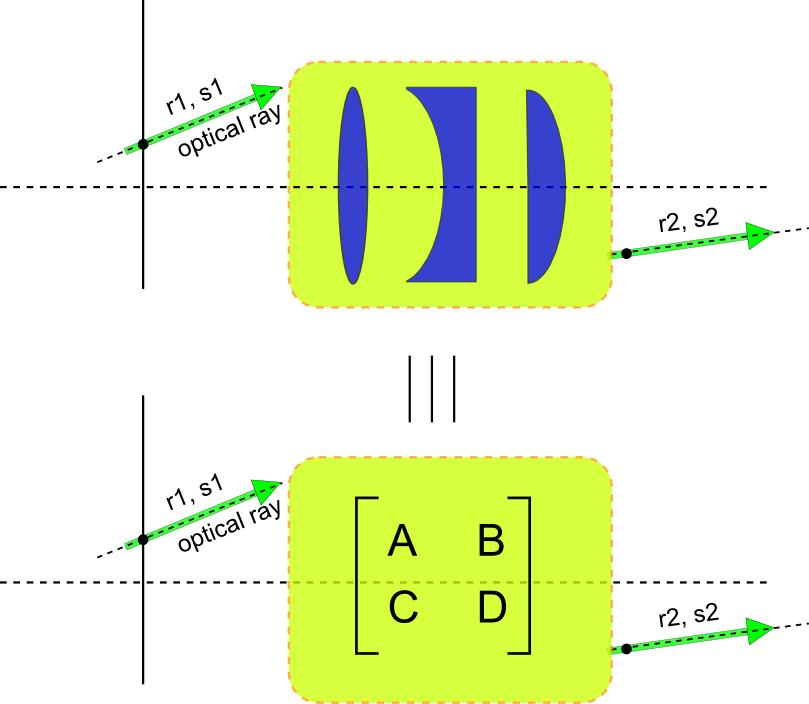
Source: OpenCavity (seghil.github.io)
2.2 Gaussian Beam Transformation
A laser beam is not ideal parallel light but has a Gaussian intensity distribution, with its radius varying with propagation distance according to the Gaussian beam equation. The transformation of a Gaussian beam by a beam expander is analysed with the q-parameter method.
The q-parameter of a Gaussian beam is defined as:

where R(z) is the wavefront curvature radius and w(z) the beam radius. After passing through an optical system described by an ABCD matrix, the output q-parameter q₂ relates to the input q₁ as:

For an ideal afocal beam expander (C=0) with the input at the waist (q₁ = i·z_R_in, where z_R_in = πw₀_in²/λ is the input Rayleigh length), we can derive:
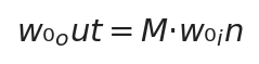
(output waist radius is M times the input)
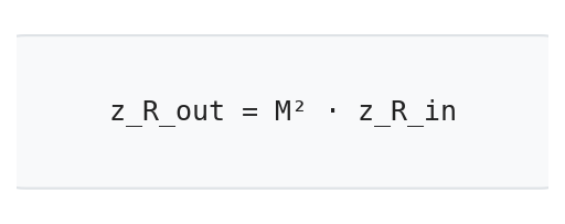
(Rayleigh length becomes M² times)
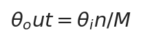
(far-field divergence compressed to 1/M)
These three formulas are the core theoretical basis for beam expander selection: expanding M times enlarges beam diameter M times, compresses divergence M times, and increases Rayleigh length M² times [(RP Photonics · Beam Expanders)](https://www.rp-photonics.com/beam_expanders.html).
The spot diameter at any position z after expansion can be calculated by:

【Figure: Gaussian beam before/after expansion comparison | Location: end of this section | Suggested source: w(z) propagation curve comparison, labeling waist and Rayleigh length before and after】
2.3 Lagrange Invariant and Étendue
The physical essence of a beam expander can be described uniformly by the Lagrange invariant (also called the optical invariant or Helmholtz-Lagrange theorem). Under paraxial conditions, for a rotationally symmetric optical system:

where constant is a constant
where n is the refractive index, y the marginal ray height, and u the marginal ray angle. This invariant stays constant throughout the optical system. For a beam expander, if beam radius y expands M times, divergence u must shrink M times, keeping the product constant [(Eckop · Étendue)](https://www.eckop.com/resources/optics/illumination/etendue/).
Generalized to two dimensions (area × solid angle), this is the étendue:

where constant is a constant
where A is the beam cross-sectional area and Ω the beam solid angle. Conservation of étendue is the optical expression of the second law of thermodynamics – passive optical elements can only transfer, not compress, phase-space volume.
【Figure: Lagrange invariant diagram | Location: end of this section | Suggested source: y-u phase-space conservation diagram, or marginal and chief ray labeling】
2.4 Transformation of Beam Pointing Stability
A beam expander changes not only beam diameter and divergence but also the pointing error of the incident beam. This is critical in high-precision optical systems.
Angular error (tilt) transformation: if the input beam has a small angular offset Δθ_in, after M-fold expansion the output angular offset becomes:
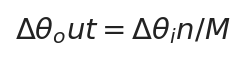
i.e. the beam expander compresses angular error by a factor of M. This is why long-distance laser transmission (such as lidar and laser rangefinding) requires expansion first – it reduces the impact of pointing deviation.
Positional error (shift) transformation: if the input beam has a lateral displacement Δy_in (beam centre offset from the optical axis), after expansion the output lateral displacement becomes:
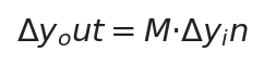
i.e. the lateral displacement error is amplified M times. This is why the input-end coaxiality of a beam expander is so important – a slight eccentricity at the input is amplified M times at the output [(RP Photonics · Beam Expanders)](https://www.rp-photonics.com/beam_expanders.html).
💡 Key conclusion: a beam expander “compresses” angular error (divide by M) and “amplifies” positional error (multiply by M). Therefore the optical path before the expander must guarantee positional accuracy (coaxiality), and the path after must guarantee angular accuracy (collimation).
==================== Chapter 3 Structure and Classification ====================
III. Structure and Classification
3.1 Classification by Optical Structure
Beam expanders fall into three structural categories: Galilean, Keplerian and reflective. Each has its own features and markedly different application scenarios.
| Comparison item | Galilean | Keplerian | Reflective |
|---|---|---|---|
| Lens combination | Negative lens + positive lens | Positive lens + positive lens | Concave mirror + convex mirror (off-axis parabolic) |
| Intermediate focus | ❌ No (no real focus in the path) | ✅ Yes (real focus between the two lenses) | ❌ No (off-axis design has no real focus) |
| Air breakdown risk | None ✅ | High ❌ (high peak power may break down air) | None ✅ |
| Structure length | Short (f₂ – |f₁|) | Long (f₁ + f₂) | Relatively short (folded path) |
| Spatial filtering | Not supported | Supported (pinhole at focus) | Not supported |
| Chromatic aberration | Present (common to refractive types) | Present (common to refractive types) | None ✅ (reflective has no chromatic aberration) |
| Thermal lens effect | Present (material absorption generates heat) | Present (material absorption generates heat) | Minimal ✅ (mirror thermal deformation is small) |
| Wavelength range | Depends on material and coating | Depends on material and coating | Extremely wide (metal coating covers UV to far IR) |
| Wavefront quality | Good (λ/4 ~ λ/10) | Good (λ/4 ~ λ/10) | Excellent (up to λ/10 or better) |
| Alignment difficulty | Medium | Medium | High (off-axis alignment complex, with double-angle issue) |
| High-magnification design difficulty | Relatively high | Relatively low | Relatively high |
| First choice for laser processing | ✅ First choice | ❌ Not recommended | For ultra-high power / special wavelengths |
▲ Table 2: Comparison of Galilean vs Keplerian vs Reflective structures
【Figure: Galilean beam expander optical path | Location: within Galilean section | Suggested source: negative + positive lens path, labeling f1 negative, f2 positive, spacing = f2-|f1|】
【Figure: Keplerian beam expander optical path | Location: within Keplerian section | Suggested source: two positive lenses + intermediate focus, labeling f1, f2, spacing = f1+f2】
【Figure: Reflective beam expander optical path (off-axis parabolic) | Location: within reflective section | Suggested source: off-axis parabolic reflective expander, concave + convex mirror off-axis configuration】
3.2 Classification by Magnification Adjustment
| Comparison item | Fixed magnification | Continuously variable (manual) | Motorized variable |
|---|---|---|---|
| Structural complexity | Simple (2 lenses) | Medium (3+ lens group) | Complex (motor + transmission + feedback) |
| Magnification range | Single fixed value (e.g. 2X, 3X, 5X, 10X) | Continuously adjustable (e.g. 2X-8X, 1X-4X) | Continuously adjustable + electronic control (same as manual) |
| Wavefront quality | Best (fixed spacing, fully optimised aberrations) | Good (must optimise at multiple positions) | Good (same as manual) |
| Beam drift | None (fixed structure) | Small for sliding type; larger for rotating type | Depends on mechanical structure |
| Adjustment method | Not adjustable | Hand rotation / sliding scale ring | Motor drive + position feedback |
| Typical applications | Mass-production equipment, fixed process | Laboratory, R&D, multi-product small batches | Automated lines, remote control, smart equipment |
| Cost | Low | Medium | High |
▲ Table 3: Fixed vs variable vs motorized magnification comparison
3.2.1 The Three-Element Principle of Variable Expanders
Continuously variable beam expanders usually adopt a three-element mechanical-compensation structure, consisting of three optical groups: a front fixed group, a variator group (movable) and a compensator group (movable). By precisely controlling the positional relationship of the two moving groups, collimation (afocal condition) is maintained at the output while magnification changes.
A typical three-element structure is a “positive-negative-positive” or “negative-positive-positive” configuration; during zooming the two lens groups move synchronously along the optical axis, keeping the system afocal at any magnification. The difficulties in system design are:
- Full-range afocal constraint: input and output must remain collimated throughout the zoom range
- Aberration balance: spherical aberration, coma, etc. must be controlled within limits at all magnifications
- Mechanical precision: coaxiality and positional accuracy of lens movement directly affect beam quality
A cemented-doublet-based low-wavefront-error variable expander can achieve about 0.1λ wavefront error (OPD) over the 2-6.4× range, with divergence about 0.05°, meeting high-quality application needs [(Optical Technology · Vol.51, 2025)](https://hpl.opticsjournal.net/Articles/OJd56d9510188faf99/FullText).
The expansion ratio formula for a reflective expander is the ratio of the radii of curvature of the two off-axis parabolic mirrors:

where R₁ is the substrate curvature radius of the concave off-axis parabolic mirror and R₂ that of the convex one, with the two mirrors confocal (spacing equal to the difference of their focal lengths). Reflective expanders achieve diffraction-limited performance with no chromatic aberration or absorption issues at all [(RP Photonics · Beam Expanders)](https://www.rp-photonics.com/beam_expanders.html).
【Figure: three-element variable expander structure diagram | Location: end of this section | Suggested source: three-group zoom path, labeling variator and compensator groups】
3.3 Classification by Application Scenario
According to different application needs, beam expanders can be classified as follows:
| Type | Typical wavelength | Material | Structure | Core feature |
|---|---|---|---|---|
| Standard type | 1064 nm, 532 nm, 633 nm | K9 / fused silica | Galilean | Cost-effective, general-purpose |
| High-power type | 1064 nm, 1070 nm | Fused silica (high-LIDT coating) | Galilean / reflective | High damage threshold, optional water cooling |
| UV type | 355 nm, 266 nm | Fused silica (UV grade) | Galilean | UV-specific coating, low absorption |
| Far-IR type | 10.6 μm (CO₂) | ZnSe / GaAs / Ge | Galilean | IR material, high transmission at 10.6 μm |
| Ultrafast type | 800 nm, 1030-1080 nm | Imported fused silica (low dispersion) | Galilean (achromatic) | Low dispersion, high LIDT, small pulse broadening |
▲ Table 4: Comparison of beam expander types by application
==================== Chapter 4 Key Parameters ====================
IV. Key Parameters in Detail
When selecting a beam expander, the following 12 key parameters must be considered. Each has a clear physical meaning and selection criterion; understanding them enables precise selection.
| Parameter name | Definition / formula | Selection significance |
|---|---|---|
| Expansion ratio / magnification M | M = D_out / D_in = f₂ / f₁ | Core parameter. Determines output beam thickness and divergence compression ratio. Constrained by the matching law; cannot be chosen arbitrarily large. |
| Input beam diameter D_in | Maximum laser beam diameter accepted at the expander entrance (1/e² definition) | Must exceed the laser output beam diameter; 20% margin recommended. Too small causes beam clipping, diffraction and power loss. |
| Output beam diameter D_out | D_out = M × D_in (design value, 1/e² definition) | Must be smaller than the clear aperture of downstream optics (galvo, scan lens); 15%-20% margin recommended. |
| Input divergence / output divergence | θ_out = θ_in / M (far-field divergence compressed M times) | Affects long-distance transmission and depth of focus. Large-magnification expansion gives smaller divergence and more stable far-field spot, but also shorter depth of focus. |
| Wavefront distortion (PV / RMS) | PV = peak-to-valley wavefront difference; RMS = root-mean-square wavefront error. RMS ≈ PV/3.5 (Gaussian error distribution) | Core indicator of optical quality. Greater wavefront distortion means the focused spot deviates further from the diffraction limit. Research grade requires RMS < λ/14; industrial grade generally λ/4 ~ λ/10. |
| Transmission efficiency | T = P_out / P_in × 100%, T_total = Π(1-R_i) (approximate, ignoring absorption) | Reflects energy loss. Quality products have single-surface reflectance < 0.5% and two-lens total transmission > 98%. Low efficiency not only wastes power but also heats the lenses. |
| Entrance pupil / exit pupil diameter | Effective clear diameter of the entrance/exit optics (note: not the outer diameter) | Physical boundary. Entrance pupil must exceed input beam, exit pupil must exceed output beam; note the effective aperture, not the lens outer diameter. |
| BFL / FFL | BFL = distance from last surface to rear focus; FFL = distance from first surface to front focus | For an afocal system the theoretical focal length is infinite, but slight misalignment introduces small focusing/divergence; BFL/FFL evaluate focusing behaviour deviating from the afocal state. |
| Beam pointing stability | Drift of output beam angle over time/temperature, typically in μrad/°C | Affects processing consistency and long-distance transmission accuracy. Thermal expansion and stress changes are the main causes; high-stability products need low-expansion materials and stable structures. |
| Zoom range (variable type) | Adjustable range from minimum to maximum magnification, e.g. 2×-8× | Wider range means more applicable scenarios, but greater optical design difficulty and possibly degraded quality at extreme magnifications. Choose by actual need. |
| Applicable wavelength range | Wavelength interval in which coating and material work properly | Coatings are wavelength-specific; wrong wavelength sharply reduces transmission. 355 nm requires fused silica; 10.6 μm uses ZnSe/Ge, etc. |
| Thread interface type | Connection thread specification at input/output ends | Directly affects mounting compatibility. Common specs: M22×0.75, M30×1, M34×1, SM1/SM2, etc. Confirm both input and output ends when selecting. |
▲ Table 5: Quick-reference table of 12 key parameters (with definitions and selection significance)
4.1 Wavefront Distortion in Depth
Wavefront distortion is one of the most important indicators of beam expander optical quality; it describes the deviation between the actual wavefront and an ideal plane wavefront.
PV value (Peak-to-Valley): the difference between the highest and lowest points of the wavefront, reflecting maximum deviation. Advantage: intuitive; disadvantage: overly sensitive to individual point errors and does not reflect overall distribution.
RMS value (Root Mean Square): the root-mean-square of wavefront error, reflecting overall wavefront quality. For Gaussian-distributed errors, RMS ≈ PV / 3.5. RMS better represents the actual optical performance of the system.

The relation between wavefront distortion and Strehl Ratio (Marechal approximation):

(when RMS is small)
It is generally accepted that when SR ≥ 0.8 (corresponding to RMS ≤ λ/14), the system reaches the diffraction limit.
Typical wavefront distortion values for different product grades:
- Research Grade: RMS < λ/14, PV < λ/4
- Industrial precision grade: RMS < λ/10, PV < λ/3
- General industrial grade: RMS < λ/4, PV < λ
【Figure: wavefront distortion diagram (PV vs RMS) | Location: end of this section | Suggested source: wavefront error surface diagram, labeling PV peak-to-valley and RMS root-mean-square】
4.2 Transmission Efficiency and Energy Loss
The transmission efficiency (transmittance) of a beam expander measures its energy-transfer capability. For a two-lens Galilean expander (four optical surfaces), the total transmission efficiency is:

where R₁~R₄ are the reflectances of the four optical surfaces. For lenses with high-quality anti-reflection coating (AR Coating), single-surface reflectance can be as low as 0.2%-0.5%, and two-lens (four-surface) total transmission can reach over 98%-99%.
Note that transmission efficiency ≠ energy utilisation. Besides surface reflection loss, there is bulk material absorption, scattering and thermal loss. For high-power lasers, even a small absorption fraction can cause significant thermal lensing.
==================== Chapter 5 Characteristics ====================
V. Core Characteristics
5.1 Basic Characteristics of Afocal Systems
As an afocal system, a beam expander has the following inherent characteristics:
- Parallel in → parallel out: for collimated input, the output remains collimated (ideally)
- Magnification conservation: beam diameter expands M times, divergence compresses M times, product constant (Lagrange invariant)
- Reversibility: used in reverse it is a beam reducer, with magnification 1/M
- No focal length: the system itself has no focus, principal planes or nodal points
5.2 The Matching Law – A Selection Red Line
In galvo scanning systems, beam expander selection must obey the matching law, an inviolable red line:
Laser output beam diameter × expansion factor ≤ galvo clear aperture ≤ scan lens entrance pupil diameter
The physical meaning of the matching law: the expanded beam must pass completely through the galvo mirror and the scan lens entrance; any clipping at any stage causes power loss, spot deformation and degraded processing quality.
⚠️ Galvo system 80%-85% margin principle: in practice, the expanded beam diameter should not exceed 80%-85% of the galvo nominal spot. Two reasons: first, when the galvo deflects, the beam projection on the mirror is elliptical, reducing effective clear diameter; second, it leaves adjustment margin so slight misalignment during alignment does not clip the beam. Configurations without margin become much harder to align [(Soar Laser · Beam Expander Selection Guide)](https://www.soar-laser.cn/en/beam-expander-selection-guide/).
5.3 Material and Wavelength Compatibility
Different laser wavelengths require different lens materials; the optical properties of the material (transmittance, refractive index, dispersion, damage threshold) directly determine expander performance.
| Material | Applicable band | Transmittance | Refractive index | Features |
|---|---|---|---|---|
| BK7 / K9 glass | 350nm – 2μm | High (>92%/surface @ visible) | ~1.52 @589nm | Cost-effective, first choice for low power; has absorption peak at 355 nm, unusable |
| Fused silica | 185nm – 2.5μm | High (>93%/surface @ UV-NIR) | ~1.46 @589nm | Good UV transmission, high damage threshold, extremely low thermal expansion; mandatory for high-power/UV/ultrafast |
| Zinc selenide (ZnSe) | 600nm – 16μm | High (up to 99% @10.6 μm with coating) | ~2.4 @10.6μm | First choice for CO₂ lasers, broad visible-IR spectrum; toxic, handle with care |
| Silicon (Si) | 1.2μm – 7μm | Medium | ~3.4 @10μm | High refractive index, high hardness; mid-IR applications, usable in some CO₂ cases |
| Germanium (Ge) | 2μm – 16μm | Low-medium | ~4.0 @10μm | Extremely high refractive index, temperature-sensitive (large dN/dT); thermal imaging / IR optics |
▲ Table 6: Common beam expander material comparison (BK7 vs fused silica vs ZnSe vs Si vs Ge)
Below is a wavelength-tiered material-power selection table, one of the most frequently consulted references in industrial selection:
| Wavelength | Low power (recommended material) | Medium power (recommended material) | High power (recommended material) | Ultrafast (ps/fs) |
|---|---|---|---|---|
| 1064 nm (fibre/nanosecond) | K9 (≤30 W) | K9 + silica hybrid (≤300 W) | Fused silica (>500 W, water cooling needed) | Imported fused silica (Corning/Ohara/Heraeus) |
| 532 nm (green) | K9 (≤10 W) | Fused silica (>10 W) | Fused silica (high-LIDT coating) | Imported fused silica |
| 355 nm (UV) | Fused silica mandatory | Fused silica (UV grade) | Fused silica (high-LIDT coating) | Imported fused silica |
| 10.6 μm (CO₂) | ZnSe (≤30 W) | ZnSe (≤200 W) | ZnSe/GaAs (water cooled) | — |
| Ultrafast (1030-1080 nm) | Fused silica | Fused silica (low-dispersion design) | Imported fused silica (achromatic + high LIDT) | Imported fused silica (femtosecond-specific) |
▲ Table 7: Wavelength-tiered material-power selection table (five wavelength tiers)
5.4 Common Expansion Ratio Specifications
| Magnification | Typical entrance pupil | Typical exit pupil | Applicable scenario | Matching galvo |
|---|---|---|---|---|
| 2X | 8-10mm | 16-20mm | Low-power marking, fine-tuning expansion | 10 mm spot |
| 3X | 6-8mm | 18-24mm | Standard marking, general processing | 14 mm spot |
| 4X | 5-6mm | 20-24mm | Precision marking, fine processing | 14 mm/20 mm spot |
| 5X | 4-5mm | 20-25mm | High-precision marking, welding | 20 mm spot |
| 6X | 3.5-4mm | 21-24mm | High-precision cutting, welding | 20 mm spot |
| 8X | 2.5-3mm | 20-24mm | Micro-machining, research | 20 mm/30 mm spot |
| 10X | 2-2.5mm | 20-25mm | Ultra-fine machining, research experiments | 20 mm/30 mm spot |
▲ Table 8: Quick-reference table of common expansion ratio specifications
==================== Chapter 6 Typical Applications and Selection Advice ====================
VI. Typical Applications and Selection Advice
6.1 Five Scenario-Based Selection Workflows
Different applications emphasise different beam expander requirements. The following are selection methodologies for five typical scenarios.
6.1.1 Laser Marking / Engraving Scenario
Core conflict: spot fineness vs marking speed vs depth of focus
Selection points:
- Fibre marker (1064 nm): normally 3X, 4X-5X for high precision, with 14 mm or 20 mm galvo
- UV marker (355 nm): must use fused silica material, magnification 3X-8X, with small-spot galvo
- CO₂ marker (10.6 μm): ZnSe material, glass-tube laser 2X-3X, RF-tube 3X-5X
- The matching law is a red line: expanded beam ≤ galvo spot × 85%
- For mass production prefer fixed magnification for reliability and low cost
6.1.2 Laser Cutting / Welding Scenario
Core conflict: power handling vs spot size vs thermal stability
Selection points:
- Power > 500 W must use fused silica material; high power recommends water-cooled structure
- The first lens (entrance end) bears the highest power density and must have a high-LIDT coating
- Large magnification (6X-10X) with large-spot galvo (20 mm/30 mm) for finer cutting kerf
- Watch thermal lensing: after long operation, lens heating changes beam quality
- Pulse welding must consider peak power; choose high damage threshold coating
6.1.3 Laser Measurement / Interferometry Scenario
Core conflict: wavefront quality vs beam uniformity vs pointing stability
Selection points:
- Prefer research-grade products, wavefront distortion RMS < λ/10 or even λ/14
- Choose Galilean structure to avoid air turbulence from an intermediate focus
- For high pointing stability, choose low-expansion materials and structurally stable products
- For zoom needs choose sliding (not rotating) variable expanders to avoid beam drift
- For interferometry choose reflective type to completely eliminate chromatic aberration and absorption
6.1.4 Research Laboratory Scenario
Core conflict: flexibility vs cost-effectiveness vs adjustability
Selection points:
- Recommend continuously variable expanders to suit many experimental needs
- Choose zoom range by experimental subject: 1X-4X (large beams) or 2X-8X (small-medium beams)
- For multi-wavelength experiments choose broadband coating models or reflective type
- Use a four-axis mount for easy optical alignment
- On a limited budget choose Galilean fixed magnification + multiple magnification sets for better value
6.1.5 High-Power / Ultrafast Laser Scenario
Core conflict: damage threshold vs dispersion control vs thermal management
Selection points:
- Femtosecond lasers must use imported fused silica (Corning 7980 / Ohara / Heraeus)
- Ultrafast lasers choose low-dispersion/achromatic design to avoid pulse broadening
- High-LIDT coating: 1064 nm ultrafast-specific coating LIDT should reach 15-30 J/cm² or above
- High-power CW lasers can use reflective beam expanders to completely eliminate thermal lensing and absorption
- Pulsed lasers must consider both average and peak power, not just average power
6.2 Parameter Comparison of Four Application Scenarios
| Parameter | Marking / engraving | Cutting / welding | Measurement / interferometry | Research experiments |
|---|---|---|---|---|
| Typical magnification | 2X-5X | 4X-10X | 3X-10X | 1X-8X (variable) |
| Wavefront quality requirement | λ/4 – λ/8 | λ/4 – λ/10 | < λ/10 (diffraction limit) | < λ/8 |
| Structure type | Galilean (fixed) | Galilean (high-power type) | Galilean / reflective | Variable / Galilean |
| Material first choice | K9 / fused silica | Fused silica (high LIDT) | Fused silica / mirror | Fused silica |
| Galvo matching margin | 80%-85% | 75%-80% | 70%-80% | Flexible configuration |
| Budget level | Medium-low | Medium-high | High | Medium |
▲ Table 9: Selection parameter comparison of four application scenarios
6.3 Seven-Step Selection Method
Following these seven steps systematically completes beam expander selection without missing key dimensions:
| Step | Action | Specific content | Judgment criterion |
|---|---|---|---|
| 1 | Confirm wavelength | Determine laser output wavelength and select the corresponding coating | 355 nm must be fused silica; 10.6 μm uses ZnSe; ultrafast uses low dispersion |
| 2 | Choose structure type | Select structure based on laser type and power level | Laser processing prefers Galilean; high power / broadband choose reflective |
| 3 | Measure incident beam diameter | Measure laser output beam diameter (1/e² definition) | Entrance pupil > incident beam diameter; 20% margin recommended |
| 4 | Check galvo and scan lens | Confirm galvo clear aperture and scan lens entrance pupil diameter | Calculate maximum usable magnification by the matching law |
| 5 | Select expansion factor | Under the matching-law constraint, choose the largest magnification for a fine spot | Beam diameter ≤ galvo spot × 80%-85% |
| 6 | Confirm power / type | Choose material and cooling method by wavelength tier; pulses consider peak power | High power choose silica; ultrafast choose imported silica; femtosecond mind dispersion |
| 7 | Confirm interface | Confirm input/output thread specs are compatible with equipment | Use adapters if mismatched; mind mounting centring |
▲ Table 10: Seven-step beam expander selection method
【Figure: beam expander selection in a galvo system | Location: start of this section | Suggested source: laser → expander → galvo → scan lens path matching diagram, labeling clear apertures at each stage】
6.4 Selection Priority Matrix
When multiple parameters constrain each other, the following priority matrix aids decision-making:
| Priority | Parameter | Degree of inflexibility | Consequence of wrong choice |
|---|---|---|---|
| ★★★★★ | Wavelength match + material | Red line, absolutely must not be wrong | Transmission collapse, lens burnout, completely unusable |
| ★★★★☆ | Matching law (magnification constraint) | Must be obeyed | Beam clipped, poor processing, power loss |
| ★★★★☆ | Structure type (Galilean vs Keplerian) | Choose Galilean for laser applications | Air breakdown, lens damage (at high power) |
| ★★★☆☆ | Aperture margin (entrance/exit pupil) | Must exceed beam + margin | Housing heats → thermal deformation → degraded beam quality |
| ★★★☆☆ | Wavefront distortion | Affects processing quality | Larger focused spot, thicker lines, reduced precision |
| ★★☆☆☆ | Transmission efficiency | Higher is better but can be compromised | Power waste, lens heating (large impact at high power) |
| ★★☆☆☆ | Interface / shape / weight | Adaptable | Need adapter ring or altered mounting |
▲ Table 11: Selection priority matrix
==================== Chapter 7 Common Misconceptions ====================
VII. Common Misconceptions (14)
There are many misconceptions in beam expander selection; the following summarises the 14 most common errors to help you avoid pitfalls.
| No. | Misconception | Wrong belief | Correct understanding |
|---|---|---|---|
| 1 | The larger the expansion ratio, the better | Larger magnification gives a smaller focused spot and better processing | Magnification is constrained by the matching law; exceeding galvo/scan lens capability is worse; larger magnification also means shorter depth of focus and greater defocus sensitivity |
| 2 | All beam expanders compress divergence | Adding an expander automatically reduces divergence | Only when the input light is collimated (small enough divergence) can an expander compress divergence by M. If the input is already highly divergent, it stays divergent after expansion, only larger in diameter |
| 3 | Galilean is simply better than Keplerian | Galilean has no focus, so it must be better | Each has its application. Keplerian supports spatial filtering (pinhole removes high-frequency noise) and is necessary in research and measurement scenarios needing a clean beam; it is just unsuitable for high-power laser processing |
| 4 | Input spot can exceed entrance pupil diameter | A little excess is fine as long as most light gets through | Hard-edge clipping of the beam produces severe diffraction rings, deforming the focused spot and increasing sidelobes, sharply degrading processing; the clipped energy also turns into heat, worsening thermal effects |
| 5 | The wider the zoom range, the more practical | Wider range covers more scenarios | Large zoom ratios are hard to design, and optical quality (wavefront distortion, aberrations) at extreme magnifications is often inferior to fixed-magnification products; complex mechanics also reduce reliability and stability and significantly raise cost |
| 6 | A beam expander can be used directly as a focusing lens | A beam expander contains a positive lens, so it should also focus | A beam expander is an afocal system with parallel input and output; it cannot focus a beam to a point. Focusing requires a separate focusing lens or scan lens. Using an expander as a focusing lens is completely wrong |
| 7 | Wavelength mismatch does not affect use | They are all made of glass, so any wavelength passes | Coatings are wavelength-specific; wrong wavelength can drop transmission from 99% to below 80%; 355 nm with K9 material is heavily absorbed and simply unusable; it may also damage the laser |
| 8 | Reflective type is only for CO₂ | Reflective type is exclusive to CO₂ lasers | Reflective type has no chromatic aberration, high damage threshold and no thermal lensing, and is equally or more suitable for high-power near-IR, ultrafast lasers, broad spectra, UV and other scenarios – only cost and alignment difficulty are higher |
| 9 | Thread interface does not affect performance | As long as it screws on, the interface spec does not matter | Thread fit precision directly affects coaxiality and perpendicularity; eccentricity causes asymmetric output spots and uneven power distribution; poor threads also introduce stress, causing lens deformation and wavefront distortion |
| 10 | Beam expanders need no alignment | Screw it on and it works, no alignment needed | Beam expander position errors are amplified M times! Slight eccentricity and tilt at the input are significantly magnified at the output, causing off-centre, elliptical, asymmetric spots and seriously degrading processing |
| 11 | Transmission efficiency equals energy utilisation | 99% transmission means only 1% energy loss | Transmission efficiency usually considers only surface reflection loss; there is also bulk absorption, scattering and coating absorption. At high power even 0.5% absorption causes significant thermal lensing and power drift |
| 12 | Wavefront distortion does not matter | As long as light passes, wavefront error is irrelevant | Wavefront distortion directly affects focused spot quality. A system with λ/2 wavefront error can have Strehl Ratio drop below 0.5, with thicker spots and larger sidelobes, greatly reducing precision and energy concentration |
| 13 | Using large magnification at high power is safe | Larger magnification means thicker beam, lower energy density, less likely to break | The first lens (entrance end) of a beam expander bears the full power regardless of magnification. At high power, the material and coating of the first lens are what matter – a high-LIDT product must be chosen |
| 14 | All Chinese-made beam expanders are about the same | They are all two pieces of glass in a tube; every brand is the same | The differences are enormous: lens material grade (K9/silica/imported silica), coating quality (LIDT, reflectance), fabrication precision (surface figure, centration), mechanical structure (coaxiality, stability) and inspection standards all vary hugely, directly affecting beam quality and service life |
▲ Table 12: Comparison table of 14 common misconceptions
==================== Chapter 8 History and Notes ====================
VIII. Development History and Technical Notes
8.1 Brief History
The concept of the beam expander originates from telescope optics. As early as the 17th century, Galileo and Kepler invented telescope structures bearing their names; these basic optical principles remain the theoretical foundation of beam expanders today.
After the invention of the laser in 1960, beam expanders developed rapidly as a key element for laser beam manipulation. Early applications were mainly in interferometry and spectroscopy to improve beam quality and resolution. In the 1970s-80s, with the rise of industrial lasers, beam expanders began to be widely used in laser processing [(mepinfo.jp · ビームエキスパンダ)](https://mepinfo.jp/%E3%83%AC%E3%83%BC%E3%82%B6/%E3%80%90%E5%85%89%E5%AD%A6%E3%80%91%E3%83%93%E3%83%BC%E3%83%A0%E3%82%A8%E3%82%AD%E3%82%B9%E3%83%91%E3%83%B3%E3%83%80/).
In China, laser expansion technology likewise went from adoption and assimilation to independent innovation. Early research aimed at simplifying system structure and improving functionality; in recent years it has deepened toward large apertures, astigmatism correction and multi-source fusion. Examples include building collimation optical system models for laser beam astigmatism, large-aperture plane-wave expansion devices for interferometers, and optimising variable expanders with nonlinear optical characteristics – all reflecting continuous innovation in the deep integration of theory and engineering practice.
Entering the 21st century, with the development of ultrafast and high-power lasers, beam expander technology has continued to evolve in the following directions:
- Low-dispersion design: to address femtosecond pulse broadening
- High damage threshold coatings: to address high peak power pulsed lasers
- Variable / motorized zoom: to address flexible adjustment across scenarios
- Reflective design: to address ultra-high power and broad-spectrum needs
- Single-element / integrated design: compact structure via a single aspheric lens
In recent years, institutions such as NIST have developed photonic-chip-based extreme-ratio expanders (up to 400×), opening new directions for integrated photonics and atomic physics research [(NIST · 2018)](https://www.nist.gov/news-events/news/2018/11/new-device-widens-light-beams-400-times-broadening-possibilities-science).
8.2 Technical Notes
- In this article, beam diameter uses the 1/e² definition unless otherwise stated (diameter where intensity falls to 1/e² ≈ 13.5% of peak)
- Expansion ratio is linear magnification (diameter ratio); area ratio is M²
- All formulas hold under the paraxial approximation; large-angle and high-NA scenarios require corrections
- In industrial selection, prioritise verifying three items: wavelength match, magnification constraint and material choice
- In actual use, perform targeted selection based on specific laser parameters and application needs; consult an optical engineer when necessary
【Figure: industrial beam expander product photo | Location: middle of this section | Suggested source: Soar Laser industrial beam expander product photo】
【Figure: installation and alignment diagram | Location: end of this section | Suggested source: expander mounting centring diagram, with four-axis mount or thread alignment operation】
==================== Chapter 9 References ====================
IX. References
- Rüdiger Paschotta, “Afocal Optical Systems”, RP Photonics Encyclopedia, https://www.rp-photonics.com/afocal_optical_systems.html
- Rüdiger Paschotta, “Beam Expanders”, RP Photonics Encyclopedia, https://www.rp-photonics.com/beam_expanders.html
- Soar Laser technical team, “Beam Expander Selection Guide: 7 Key Points to Get It Right the First Time”, May 2026, https://www.soar-laser.cn/en/beam-expander-selection-guide/
- Soar Laser technical team, “Laser Beam Expander Technical Details and Application Selection Guide”, April 2026, https://www.soar-laser.cn/en/laser-beam-expander-guide/
- Newport, “How to Build a Beam Expander”, https://www.newport.com/n/how-to-build-a-beam-expander
- Thorlabs, “Optical Beam Expanders” product manual, https://www.thorlabs.com/
- Edmund Optics, “Research-Grade Variable Beam Expanders” product specs, https://www.edmundoptics.com/
- Liu Yuchen et al., “Design of a low-wavefront-error variable beam expander system based on cemented doublets”, Optical Technology, Vol.51 No.5, 2025, https://hpl.opticsjournal.net/Articles/OJd56d9510188faf99/FullText
- Photonics Spectra, “New Approaches Improve Beam Expansion”, March 2014, https://www.photonics.com/Articles/New_Approaches_Improve_Beam_Expansion/p5/a55925
- Sichuan Sploptics Technology, “Optical Invariant Principle and Illustration”, https://www.sploptics.com/pages/know-etendue.html
- Asphericon, “Beam Expansion” technical blog, https://www.asphericon.com/en/blog/160811-beam-expansion/
- Jenoptik, “Beam Expander 1x-4x Fused Silica Systems” product manual, https://www.jenoptik.com/
- S. Kim et al., “Photonic waveguide to free-space Gaussian beam extreme mode converter”, Light: Science & Applications, 2018, NIST report
- F. J. Duarte, “Tunable Laser Optics”, Elsevier Academic Press, 2003
- J. Wilson and J.F.B. Hawkes, “Optoelectronics: An Introduction”, Prentice Hall, 1998
==================== Bottom Dual Modules ====================
Further Reading
📖 Further Reading
- 🔹 Beam Expander Selection Guide: 7 Key Points to Get It Right the First Time
- 🔹 Laser Beam Expander Technical Details and Application Selection Guide
- 🔹 F-theta Lens Encyclopedia
- 🔹 Laser Collimator Encyclopedia
- 🔹 Complete Guide to Galvo Selection
- 🔹 RP Photonics: Beam Expanders (English)
- 🔹 RP Photonics: Afocal Optical Systems (English)
- Laser Protective Window Encyclopedia: Selection and Materials for Cutting / Welding / Scan Lens / Galvo Protection
Related Products
🔗 Related Products
- ✨ Fibre Laser Beam Expander (1064 nm, 2X-10X Galilean)
K9 / fused silica options, M22/M30 thread interfaces - ✨ UV Laser Beam Expander (355 nm, 3X-8X fused silica)
UV-grade fused silica, high-LIDT coating, never K9 - ✨ CO₂ Laser Beam Expander (10.6 μm, ZnSe material)
Zinc selenide, for glass-tube / RF-tube CO₂ lasers - ✨ Continuously Variable Beam Expander (2X-8X manual zoom)
Sliding design, low beam drift, first choice for research / R&D - ✨ High-Power Water-Cooled Beam Expander (500W+ fused silica)
Water-cooled structure, low thermal lensing, for cutting / welding - ✨ Ultrafast Laser Beam Expander (femtosecond / picosecond, imported fused silica)
Low-dispersion design, high-LIDT coating, Corning / Ohara / Heraeus silica
💡 Selection consultation: for technical selection support, please contact the Soar Laser technical team; we offer free optical path design and beam expander selection services.
This article was written by the technical team of Changsha Soar Laser Equipment Co., Ltd. | Last updated: 2026 | Please cite the source when reprinting
Leave a Reply