


Have you ever wondered why a laser marker can “draw” such neat text and patterns on metal and plastic surfaces? The galvo clicks and turns, the beam sweeps back and forth, and whether in the centre or at the edge, the lines are equally thin and equally deep. The “magic prop” behind this is today’s subject – the F-Theta scan lens.
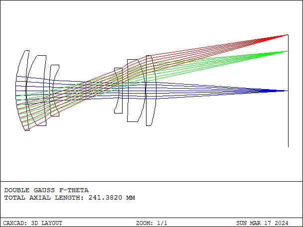
Sounds professional? Don’t worry – in one sentence: it is the “flat-field magnifier” in a laser scanning system, letting the laser focus uniformly on a flat work surface, with the spot size and speed identical wherever it scans. Without it, a laser marker’s text might be clear in the centre and blurry at the edges, or even get larger toward the edges.
In this article we break the F-Theta scan lens down completely – what it is, how it works, how to read the key parameters, what types exist, where it is used, and the most common pitfalls in selection.
Table of Contents
- I. Core Concept: What Exactly Is an F-Theta Scan Lens?
- II. How It Works: Why “f-θ”? How Is the Flat-Field Magic Achieved?
- III. Key Parameters: Which Specs Matter When Choosing a Scan Lens?
- IV. Types: How to Choose by Wavelength, Application, Telecentric or Not
- V. Applications: Where Else Are Scan Lenses Used?
- VI. Common Misconceptions: 4 Pitfalls to Avoid
- Related Product Recommendations
I. Core Concept: What Exactly Is an F-Theta Scan Lens?
An F-Theta scan lens is also called an f-θ lens, scan lens or flat-field focusing lens – many names, all referring to the same thing. It is not a single lens but an optical assembly composed of multiple lens elements, designed specifically for laser scanning systems.
It has two core missions:
First, focus the laser onto a flat work surface. A normal lens has a spherical focal surface, like the bottom of a bowl – clear in the centre, blurry at the sides. Through a clever combination of multiple lenses, the F-Theta scan lens “flattens” the foci so that spots across the entire scan range land on the same plane. That is the origin of the term “flat-field.”
Second, make spot displacement proportional to scan angle. However far the galvo turns, the spot moves that far on the workpiece – a linear relation. This makes the control system simple: give an angle command and the spot moves a corresponding distance, with no complex nonlinear correction needed.
A simple comparison: a normal lens is like an old magnifying glass, with different magnification at centre and edge; an F-Theta scan lens is like a precise ruler, with every division evenly spaced.
In laser marking, cutting and 3D printing equipment, the F-Theta scan lens is the key element ensuring consistent processing quality. It is fair to say that without a good scan lens, there is no high-precision laser processing.
II. How It Works: Why “f-θ”? How Is the Flat-Field Magic Achieved?
2.1 The Difference Between f·tanθ and f·θ
First the name. “F-Theta” comes from a mathematical formula.
For an ordinary spherical lens, the relation between image height (the spot’s distance from centre) and scan angle θ is:
y = f · tan(θ)
See? It is a tangent (tan) relation, not linear. The larger the scan angle, the faster image height grows. What does that mean? When the galvo rotates at constant speed, the spot moves much faster at the edge of the workpiece than at the centre – resulting in inconsistent marking depth, uneven line width and blurring toward the edges.
The brilliance of the F-Theta lens is that through deliberately introducing controlled barrel (negative) distortion, it corrects the tangent relation into an approximately linear one:
y ≈ f · θ
θ is in radians. Thus, when the galvo rotates at constant speed, the spot moves at constant speed on the workpiece, and the control system only needs a simple proportional mapping.
In plain terms: a normal lens “flies faster the farther out you go,” while an F-Theta scan lens is “steady wherever it goes.”
2.2 How Is the Flat Field Achieved?
Besides linear correction, the F-Theta scan lens has another important ability – field-curvature correction.
A normal lens has a spherical focal surface, like burning paper with a magnifying glass in sunlight: only the centre point is sharp, and moving toward the edge blurs. That is the field-curvature effect.
Laser processing needs a flat work surface – the workpiece is flat, so the focal surface must be flat too, otherwise the centre is cut too deep and the edge too shallow, raising the scrap rate.
Through a combination of multiple lenses with different curvatures and materials (typically 3-6 elements), the F-Theta scan lens precisely corrects field curvature so that foci across the entire scan range lie approximately on the same plane. That is the origin of the name “flat-field focusing lens.”
So you see, behind the name “F-Theta” lie two core design goals: linear displacement (f·θ) + flat-field focusing. Neither can be omitted.
III. Key Parameters: Which Specs Matter When Choosing a Scan Lens?
When buying a scan lens, the spec sheet lists a dizzying array of parameters. Actually only a few are core; understand them and you can quickly judge whether one suits your application.
3.1 Effective Focal Length
This is the most core parameter, determining how large the scan field is and how fine the spot is. Common focal lengths range from 100 mm to 800 mm.
General rule: a longer focal length gives a larger scan field but also a larger spot and lower resolution. So focal length is not “the larger the better” – choose by your processing needs. Fine small-field marking uses a short focal length; large-field processing uses a long one.
3.2 Scan Field / Marking Area
This is the maximum processing area, e.g. 100×100 mm or 200×200 mm. It is determined jointly by focal length and scan angle.
Note: does the scan field refer to the diagonal or the side length? Different manufacturers may label differently – always confirm when selecting. Usually the spec sheet states explicitly “100×100 mm” or “Ø175 mm,” etc.
3.3 Entrance Pupil Diameter
The incident beam diameter the scan lens can accept. This parameter is very important because it directly affects focused spot size – a larger entrance pupil gives a smaller spot and higher resolution.
But the entrance pupil is not “the larger the better” either; too large raises design difficulty and cost, and it must match your laser beam diameter. Generally the incident beam diameter should be slightly smaller than the entrance pupil, leaving a little margin.
3.4 Spot Size
The diameter of the focused spot on the focal plane. This is the parameter everyone cares about most – a smaller spot means finer processing.
Spot size is determined by three factors: wavelength, focal length, and incident beam diameter. The formula is roughly: spot diameter ≈ 1.27 × λ × f / D (λ = wavelength, f = focal length, D = incident beam diameter).
So shorter wavelength, shorter focal length and thicker beam give a smaller spot. That is why UV lasers (355 nm) do ultra-fine marking, while CO₂ lasers (10.6 μm) have larger spots suited to cutting thick materials.
3.5 F-Theta Distortion
The deviation between actual position and the ideal f·θ linear relation, usually expressed as a percentage.
Quality designs can reach below 0.1%; ordinary ones are roughly 0.2%-0.5%. This parameter directly affects marking position accuracy – greater distortion means more obvious edge-position error.
However, some nonlinear errors can be compensated through software correction, so there is no need to blindly pursue the lowest distortion.
3.6 Telecentricity
The angle between the chief ray (the ray through the centre of the aperture stop) and the optical axis. In a telecentric design this angle approaches 0°, meaning chief rays always strike the workpiece perpendicularly.
The benefits of a telecentric scan lens are: more uniform spots and insensitivity to workpiece height variation. The cost is a smaller field and higher price. We cover this in detail in the classification section.
3.7 Operating Wavelength and Transmittance
A scan lens is optimised and coated for a specific wavelength – common ones are 355 nm (UV), 532 nm (green), 1064 nm (fibre/YAG) and 10.6 μm (CO₂).
This point is critical: scan lenses with mismatched wavelengths must never be interchanged – at best poor results, at worst damaged optics.
3.8 Working Distance
The distance from the last lens surface to the focal plane. This affects whether you can fit the workpiece in and whether there is room for other accessories. Too short a working distance makes fixturing inconvenient; too long affects overall structural stability.
📊 Core Parameter Quick-Reference Table
| Parameter | Meaning | Unit / typical value | Selection point |
|---|---|---|---|
| Effective Focal Length (EFL) | The scan lens’s focal length, determining scan field and spot size | 100~800mm | Longer focal length means larger field but larger spot; balance precision and range |
| Scan field | Effective processing range | e.g. 100×100 mm, 300×300 mm | Leave 10-20% margin; beyond-field use severely degrades edge quality |
| Entrance pupil diameter | Maximum incident beam diameter the scan lens accepts | mm | Larger pupil gives smaller spot but higher cost; must match beam diameter |
| F-Theta distortion | Deviation of actual position from ideal f·θ linear relation | <0.1% ~ <0.5% | Quality design <0.1%, general marking within 0.5%; partly software-compensable |
| Telecentricity | Angle between chief ray and optical axis (in telecentric design) | ° | Smaller is better; telecentric scan lenses typically <1°-3° |
| Operating wavelength | Wavelength the design is optimised for | 355/532/1064 nm, 10.6 μm | Must strictly match laser wavelength, otherwise poor focus and possible optic damage |
| Working distance (WD) | Distance from last lens surface to focal plane | mm | Affects fixturing space; longer WD is more convenient but costlier |
IV. Types: How to Choose by Wavelength, Application, Telecentric or Not
4.1 By Wavelength
UV scan lens (~355 nm) – mainly for fine marking, PCB drilling, wafer processing and similar. Short UV wavelength and small spot enable micron-level precision, but high photon energy demands better lens materials and coatings.
Visible scan lens (532 nm green, etc.) – green laser applications are relatively niche, mainly in special-material processing and research.
Near-IR scan lens (1064 nm) – the most mainstream type, matching fibre and Nd:YAG lasers. Most industrial marking, cutting and welding applications use this wavelength.
Far-IR scan lens (10.6 μm) – designed specifically for CO₂ lasers. The long wavelength gives a relatively larger spot, suited to cutting and engraving thick materials. CO₂ scan lenses are usually made of IR materials such as zinc selenide (ZnSe).
4.2 By Application
Marking scan lens – standard f-theta design, cost-effective, the highest-volume type. Marking has moderate precision needs; ordinary non-telecentric designs suffice.
Cutting / drilling scan lens – usually telecentric to ensure perpendicular incidence, giving neater cuts and more vertical hole walls. These lenses demand higher spot quality.
3D printing scan lens – SLS/SLM additive manufacturing needs large-field, energy-uniform scanning, so the field is usually large and energy uniformity across the whole field is critical.
Ultrafast laser scan lens – femtosecond and picosecond lasers have broad spectra and need achromatic design, otherwise different wavelengths focus at different positions and the spot broadens severely. Ultrafast scan lenses are difficult and costly to design.
4.3 Telecentric vs Non-Telecentric
This is a very important classification dimension in scan lens selection, and many people confuse it.
The feature of telecentric design is that chief rays always strike the workpiece surface perpendicularly. Its advantages:
- Spots are more uniform across the whole field
- Insensitive to workpiece height variation (a little higher or lower is fine)
- More vertical cut edges, suited to cutting and drilling
The drawbacks are equally obvious:
- Smaller field (generally not large)
- Complex structure and high cost (possibly 2-3 times a non-telecentric of the same spec or more)
- Larger size and weight
Non-telecentric design is the opposite:
- Simple structure, low cost
- Field can be made very large
- The mainstream choice for general applications such as marking
So how to choose? In one sentence: for applications insensitive to incidence angle, such as marking and engraving, non-telecentric is enough; for cutting, drilling and precision micromachining, choose telecentric.
V. Applications: Where Else Are Scan Lenses Used?
F-Theta scan lenses are used far more widely than you might think – basically anywhere laser scanning and focusing is needed.
5.1 Laser Marking / Engraving
This is the most mainstream F-Theta application. Whether metal, plastic, ceramic, glass, wood or leather, a laser marker cannot do without it. High speed, no distortion and good consistency – these three features make marking results both clear and uniform.
The fine serial numbers, QR codes and logos you see on electronic products mostly owe their existence to an F-Theta scan lens.
5.2 Laser Cutting / Drilling / Welding
In micromachining, paired with a telecentric scan lens, it enables high-precision vertical cuts and drilled holes – such as micro-hole machining of PCBs, precision cutting of thin metal sheets, laser welding of medical devices, etc.
These applications demand high spot quality and incidence angle, so telecentric-design scan lenses are generally used.
5.3 3D Printing / Additive Manufacturing
In SLS (selective laser sintering) and SLM (selective laser melting) equipment, the laser must scan and sinter over a large powder bed. The F-Theta scan lens ensures uniform energy distribution over the whole processing plane, avoiding over-sintering in the centre and under-sintering at the edges.
As metal 3D printing develops, demand for large-field, high-power F-Theta scan lenses is growing rapidly.
5.4 Biomedical Imaging
This one is relatively obscure. Confocal microscopy, scanning laser ophthalmoscopes and OCT (optical coherence tomography) also use similar scanning-lens principles. Medical scan lenses, however, demand higher imaging quality and aberration correction.
5.5 Other Applications
There is also laser display (laser TVs, laser projection), LiDAR (laser radar), laser direct-write lithography, etc. Basically any “scan + focus” combination relies on the F-Theta concept.
VI. Common Misconceptions: 4 Pitfalls to Avoid
Myth 1: The longer the focal length, the better
Many people think “longer focal length = larger field = more capable,” so they choose the longest they can. But while a longer focal length does enlarge the scan field, spot size grows proportionally and processing resolution drops.
For example, with the same incident beam and wavelength, increasing focal length from 100 mm to 200 mm roughly doubles the spot diameter. Where you could mark a 0.1 mm fine line, you now only get 0.2 mm.
Correct approach: choose focal length by actual processing needs – short for fine work, long for large field, finding the balance between precision and field.
Myth 2: The lower the distortion, the better the value
Pursuing extreme low distortion sounds great, but cost rises steeply. A 0.5% distortion lens and a 0.1% one may differ several-fold in price.
In reality, for ordinary marking, distortion below 0.5% is entirely adequate. And some nonlinear errors can be compensated by software – no need to solve everything with optical hardware.
Correct approach: choose the distortion grade by the application’s precision needs; don’t blindly pursue the lowest.
Myth 3: Scan lenses are universally interchangeable
This is the most dangerous misconception. A scan lens is optimised for a specific wavelength, power and beam diameter:
- Wavelength mismatch – a UV lens cannot be used with an infrared laser because material and coating do not match. At best low transmission and poor results; at worst damaged coating or a burned lens.
- Power mismatch – a low-power lens used with a high-power laser may thermally deform or even crack from excessive absorption.
- Beam diameter mismatch – too thick a beam causes clipping; too thin wastes the entrance pupil and enlarges the spot.
Femtosecond lasers are even more special – they require an achromatic scan lens, otherwise different wavelengths focus at different positions, the spot broadens severely and processing quality suffers greatly.
Correct approach: strictly match the scan lens to the laser’s wavelength, power and beam diameter; don’t use it carelessly.
Myth 4: Telecentric scan lenses are always better than non-telecentric
Telecentric scan lenses sound “premium,” and many think if telecentric is better, just buy telecentric. But while telecentric design offers perpendicular incidence and more uniform spots, it has a smaller field and significantly higher cost.
For marking and engraving, which are insensitive to incidence angle, non-telecentric f-theta offers a better balance of performance and cost. Spending 2-3 times more on a telecentric lens for ordinary marking is pure waste.
Correct approach: choose telecentric for applications needing perpendicular incidence such as cutting and drilling; non-telecentric is enough for general applications such as marking and engraving.
Related Product Recommendations
If you need to buy an F-Theta scan lens, browse our F-Theta scan lens product zone, covering full ranges from well-known brands such as Jenoptik, with 355 nm / 532 nm / 1064 nm and other wavelengths and a rich choice of focal lengths and fields. Our professional technical team provides selection consulting to help you find the best scan lens solution.
📖 Source statement: This article is compiled from public technical materials including RP Photonics Encyclopedia, Sill Optics technical guides and CASTECH technical analysis, edited and organised by the Soar Laser team, for technical exchange reference only. If you have any questions or suggestions, please contact us.
Further Reading
- What Is a Galvo Scanner? The Hidden Tech Behind the “Wagging Little Mirrors” in Laser Markers
- Telecentric Scan Lenses Explained: Why Laser Drilling Needs One, and How They Differ from Standard F-Theta Lenses
- What Is a Flat-Field Lens? Understand Its Principles, Differences from F-Theta Scan Lenses, and Selection Tips
Reference Sources
- RP Photonics Encyclopedia: F-Theta Lenses
- ISO 10110 Optics and Photonics – Preparation of drawings for optical elements and systems
- “Principles and Applications of Lasers”, Higher Education Press
Leave a Reply