


I. Terminology
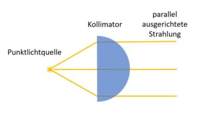
Figure 1 Collimating-lens working principle (plane side faces the point source, convex side emits parallel light)
Source: RP Photonics
A laser collimating lens (Laser Collimating Lens / Collimator Assembly) in the industrial laser field usually refers to a collimator assembly (collimation system) — a complete optical-mechanical component whose core function is to convert a diverging beam into a low-divergence parallel beam, compressing the divergence angle so the beam’s cross-section changes as little as possible during propagation.
A complete collimator assembly is more than a single optical lens; it usually has three parts: the lens group (one or more lenses, the optical core doing the collimation), the barrel/housing (a precision-machined metal shell that holds and protects the lenses and ensures coaxiality) and the mounting interface (the mechanical interface to the light source or downstream optics, such as QBH, SMA, FC). What you buy is a ready-to-use complete device that screws on and works, not a bare lens you must assemble and align yourself.
In plain terms: light from a fibre end face or laser diode spreads out like a flashlight beam. A collimator “straightens” this spreading light into a nearly parallel beam, so it can transmit stably, focus precisely or travel long distances in downstream optics. From the optical definition, a collimator is essentially a converging lens system — when the point source sits exactly at the lens’s front focal point, the outgoing rays are parallel to the optical axis, forming a collimated beam [(RP Photonics)](https://www.rp-photonics.com/beam_collimators.html).
Collimators are found in almost every laser system: from fibre-laser output heads, laser cutting heads and welding heads to optical-communication modules, LiDAR and spectrometers — all rely on the collimator’s beam shaping. It is the first optical gate in the path of laser energy from source to workpiece.
II. Physical principles
2.1 Fundamentals of geometrical optics
From geometrical optics, the collimator’s principle is very intuitive: place a point source at the front focal plane of a converging lens and the outgoing rays are parallel. For an ideal point source exactly at the focus, the divergence angle of the outgoing beam is zero (the geometrical-optics limit) [(IEEE TechNav)](https://technav.ieee.org/topic/optical-collimators/).
But real sources always have some size. For a source of diameter d, the residual half-divergence angle is approximately:

where f is the lens focal length. A longer focal length or smaller source gives better collimation.
2.2 Gaussian beams and the diffraction limit
A laser beam is not a geometrical ray but a Gaussian beam with wave properties. Even a perfectly collimated Gaussian beam diverges slowly due to diffraction. The core parameter describing collimation performance is the Rayleigh length:

where w₀ is the beam-waist radius and λ the wavelength. The Rayleigh length is the distance over which the beam travels from the waist until its spot area doubles; it is proportional to the square of the waist radius — meaning that to obtain a longer collimation distance you must use a larger beam diameter [(RP Photonics – Collimated Beams)](https://www.rp-photonics.com/collimated_beams.html).
For example, a beam at 1064 nm with a waist radius of 1 mm has a Rayleigh length of about 3 m — considered well collimated at the lab scale; but if the waist radius shrinks to 100 μm, the Rayleigh length drops sharply to about 3 cm and the beam diverges quickly.
2.3 Post-collimation spot-size formula
The collimated beam radius wcol relates to the incident divergence angle θ and lens focal length f (paraxial approximation) as:

For fibre sources, engineers more often use the clear-aperture formula:

where θ is the fibre’s full divergence angle and f the collimator focal length. For example, a collimator with a 10° divergence angle and 150 mm focal length gives an outgoing spot about 26.25 mm in diameter [(IndustryinChina)](https://www.industryinchina.com/blog/collimating-lenses-vs-beam-expanders-in-laser-cutting-key-differences-explained-1780482499).
2.4 Diffraction limit and the M² factor
Real-beam collimation performance is limited by the beam-quality factor M². M² = 1 corresponds to an ideal Gaussian beam (diffraction-limited); larger M² means poorer beam quality. For a non-ideal beam, the effective Rayleigh length shortens in proportion to M²:

This means that at the same waist radius, poorer beam quality gives a shorter collimation distance [(IEEE TechNav)](https://technav.ieee.org/topic/optical-collimators/).
III. Structure and classification
Laser collimators can be classified along several dimensions, each corresponding to different applications and performance metrics.
3.1 Classification by lens count and structure
| Structure type | Construction | Features | Typical applications |
|---|---|---|---|
| Single-lens collimation | Single plano-convex / bi-convex / aspheric lens | Simple structure, low cost, small size; spherical lenses have spherical aberration | Low-precision pointing, simple collimation, low-power cases |
| Double-lens group (achromatic doublet) | Two lenses of different materials cemented | Corrects chromatic aberration and part of spherical aberration, better than a single lens | Broadband sources, multi-wavelength systems, medium precision |
| Triple-lens group (achromatic triplet / triplet) | Three lenses combined | Best chromatic correction, lower wavefront error, near diffraction-limited | High-precision interferometry, research-grade systems, high-power industrial lasers |
An aspheric lens is the high-end choice in single-lens collimation. By changing the surface from spherical to an aspheric profile, spherical aberration is fundamentally eliminated — a single aspheric lens can match a multi-lens spherical combination, so it is widely used in laser-diode collimation and fibre coupling [(Thorlabs Lens Tutorial)](https://www.thorlabs.com/newgrouppage9.cfm?objectgroup_id=8790).
3.2 Classification by working principle: refractive vs reflective
Refractive collimators work by lens refraction and are the most common type. Advantages: compact, relatively low cost, easy to mass-produce; disadvantages: chromatic aberration, and different materials needed for different bands.
Reflective collimators usually use an off-axis parabolic mirror (OAP), collimating by reflection. Their core advantage is zero chromatic aberration and an extremely wide wavelength range (UV to far-IR), especially suited to UV and far-IR bands where glass absorbs heavily, and to broadband / multi-wavelength applications [(RP Photonics)](https://www.rp-photonics.com/beam_collimators.html). But reflective structures are larger, demand higher alignment precision and cost more.
3.3 Classification by operating wavelength
- Visible band (400–700 nm): commonly BK7 optical glass, widely used for laser pointing, measurement and alignment
- Near-IR band (700–2000 nm): commonly fused silica; fibre lasers at 1064 nm are the mainstream and the mainstay of industrial laser processing
- Mid/far-IR band (above 2 μm): commonly ZnSe, ZnS etc.; CO₂ lasers at 10.6 μm are typical
- UV band (below 400 nm): commonly fused silica, CaF₂ etc., with very high demands on material purity and coatings
3.4 Classification by collimation dimension
Most collimators collimate in both transverse dimensions, producing a circular or elliptical beam. But there are also one-dimensional collimators, such as the Fast Axis Collimator, usually a rod lens that collimates only the fast-axis direction of a laser diode, often paired with a slow-axis collimator for beam shaping of high-power diode stacks.
3.5 Classification by interface type
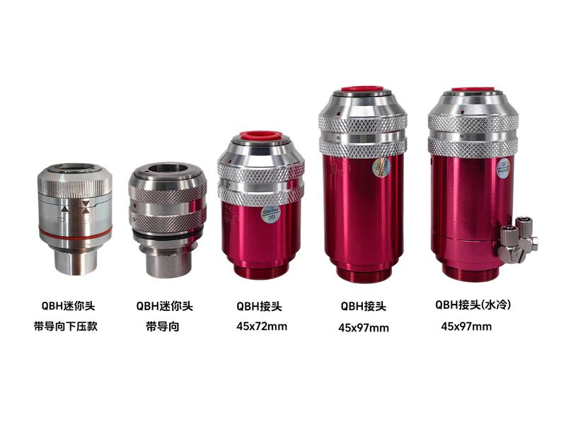
Figure 2 Industrial fibre-laser collimator assembly (QBH interface, with water-cooled version)
Source: Thorlabs
The interface type of an industrial collimator determines whether it can physically mate with an existing system, and is the first thing to confirm when selecting. Common interfaces:
- QBH interface: the industry-standard output interface for high-power fibre lasers (Quartz Block Holder), handling kilowatt to 10-kW class power, the most mainstream collimator interface in fibre-laser cutting, welding and cladding equipment. QBH has built-in water-cooling channels and safety interlocks for long continuous runs at high power [(Wavelength Opto-Electronic)](https://wavelength-oe.com/laser-optics/laser-collimators/).
- QD interface: another fibre output interface (Quartz Diode, sometimes QD/Q+), similar in structure to QBH but different in size; found on some imported fibre-laser brands. Always confirm whether the laser output head is QBH or QD — the two are not interchangeable.
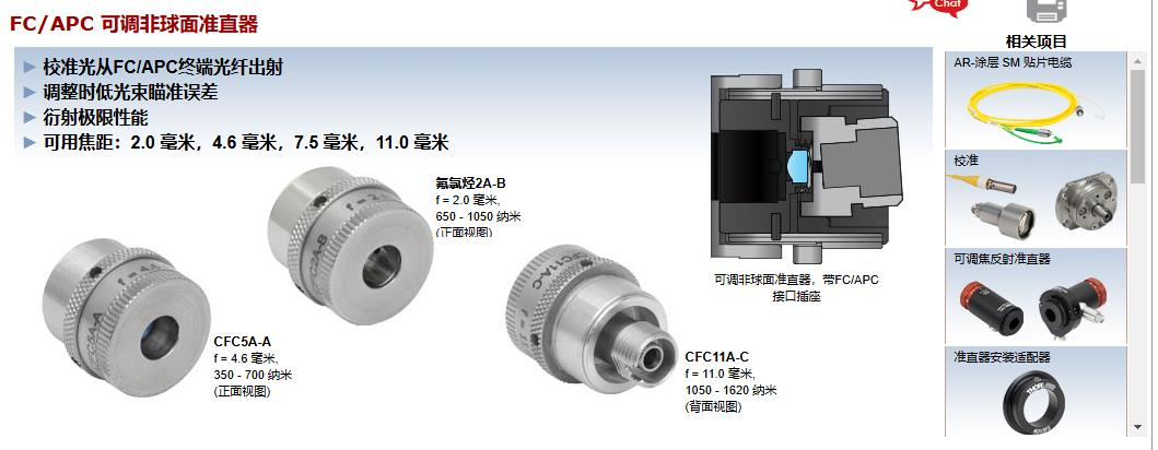
Figure 3 FC/APC interface adjustable aspheric fibre collimator
Source: Thorlabs
- FC/PC and FC/APC interfaces: standard interfaces for low- to mid-power fibre collimators; FC means Ferrule Connector. PC (Physical Contact) is flat contact, APC (Angled Physical Contact) is 8° angled contact. The angled APC design deflects back-reflection at the glass-air interface out of the fibre core, greatly reducing return loss, suited to feedback-sensitive single-frequency lasers and precision measurement systems [(RP Photonics)](https://www.rp-photonics.com/beam_collimators.html).
- SMA interface: SMA905 is the most common interface for large-core fibre (hundreds of μm to 1 mm), a threaded design that is easy to install but slightly less coaxially precise than the FC series. Often used with multimode fibre, high-power pump lasers and spectroscopic instruments.
- Free-space mounting: no fibre interface; mounted directly into the optical system via barrel threads (e.g. M9×0.5, SM1, SM2) or a flange. Suited to laser-diode collimation and free-space optics setups; the user must align source and lens [(Thorlabs)](https://www.thorlabs.com/newgrouppage9.cfm?objectgroup_id=12211).
IV. Key parameters
| Parameter name | Meaning | Selection significance (why it matters) |
|---|---|---|
| Effective focal length EFL (Effective Focal Length) |
Distance from the lens’s rear principal plane to the focus; the core parameter determining outgoing spot size | Directly sets the collimated spot diameter (D ≈ 2·f·tan(θ/2)). A longer focal length gives a larger spot and longer collimation distance, but also a larger lens aperture and mechanical size, complicating the system design. Select to match the clear aperture of downstream optics (e.g. focusing lens, galvo) [(Thorlabs)](https://www.thorlabs.com/newgrouppage9.cfm?objectgroup_id=8790) |
| Numerical aperture NA (Numerical Aperture) |
A dimensionless measure of the lens’s light-gathering ability, NA = n·sin(α), α being the max angle between edge ray and optical axis | The collimator’s NA must exceed the source’s NA or beam clipping occurs, causing power loss and diffraction rings. Rule of thumb: lens NA should be about twice the source NA to collect over 99% of the light. Insufficient NA is the most common selection error [(RP Photonics)](https://www.rp-photonics.com/beam_collimators.html) |
| Incident spot diameter / clear aperture CA |
The maximum beam diameter the lens can actually pass | The clear aperture determines whether the lens can fully accept the incident beam without clipping. For a given NA and focal length, CA ≈ 2·f·NA. Leave margin in selection to avoid edge-ray diffraction and aberrations |
| Output divergence angle | Residual divergence of the collimated beam, usually expressed as full or half angle, in mrad or ° | The core indicator of collimation quality. Smaller divergence means less spot expansion over distance. High-precision systems require residual divergence < 0.1 mrad. Divergence also directly affects final focused-spot size — larger divergence gives a larger focused spot [(RP Photonics)](https://www.rp-photonics.com/beam_collimators.html) |
| Operating wavelength range | The wavelength band for which the lens is optimised, determined by substrate and anti-reflection coating together | The lens performs best at the design wavelength (most accurate EFL, lowest wavefront error). Off design wavelength, focal length shifts, transmission drops and aberrations grow. Severe mismatch can markedly degrade collimation or even damage the coating [(GH Optics / AMS)](https://www.ghoptics.cn/news_more.html?article_id=91) |
| Interface type | The mechanical interface between the collimator and source/optics, such as QBH, QD, FC/PC, FC/APC, SMA905, free-space threads | Determines whether the collimator can physically mate with an existing system — the first gate in selection. Different interfaces differ in coaxial precision, power handling and return-loss characteristics: QBH suits kilowatt-class fibre lasers; FC/APC has low return loss for precision systems; SMA suits large-core multimode fibre. Interface mismatch is the most common purchasing mistake |
| Laser-induced damage threshold LIDT (Laser Induced Damage Threshold) |
The maximum laser power density or energy density an optical component can withstand, usually in W/cm² (CW) or J/cm² (pulsed) | The safety floor of high-power laser systems. Insufficient LIDT causes coating damage and substrate cracking, ending in permanent failure. Select LIDT at least 3× the actual power density for safety margin. CW damage is mainly thermal; pulsed damage comes from electronic stripping [(Thorlabs)](https://www.thorlabs.com/newgrouppage9.cfm?objectgroup_id=149) |
| Lens material | The optical material of the lens, such as BK7 glass, fused silica, ZnSe, CaF₂ | Determines the applicable wavelength range, transmission, thermal stability and damage threshold. BK7 for low-cost visible and near-IR; fused silica is the standard for 1064 nm fibre lasers with better thermal stability and damage threshold; ZnSe for CO₂ 10.6 μm mid-IR; CaF₂ for deep UV |
V. Characteristics
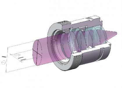
Figure 4 Cross-section of a collimator assembly (lens group + barrel + threaded interface)
Source: Edmund Optics
5.1 Core characteristics
The core characteristics of a laser collimator can be summarised as follows:
High laser damage threshold: industrial collimators generally use fused-silica substrates with dual-side AR coatings, withstanding kilowatt or even 10-kW-class continuous power. For example, collimators for fibre-laser cutting reach over 99.98% transmission, with LIDT far above ordinary optics [(Dingxinsheng Optics)](https://www.dxs-gx.com/wap/product-detail-267.html).
Controllable wavefront quality: high-end collimators keep wavefront error below λ/4 RMS, some reaching λ/10, near diffraction-limited. Wavefront quality directly determines whether downstream focusing lenses can converge the beam to the theoretical minimum spot.
Preserves source intensity distribution: a collimator changes only beam divergence, not the shape of the intensity distribution — a Gaussian beam from single-mode fibre stays Gaussian after collimation, and a flat-top/speckle distribution from multimode fibre keeps its spatial character [(RP Photonics)](https://www.rp-photonics.com/beam_collimators.html).
5.2 Collimator vs focusing lens vs beam expander
These three lens types are the most confusing in laser systems; their essential difference lies in input/output state and functional role:
| Comparison dimension | Collimator | Focusing lens | Beam expander |
|---|---|---|---|
| Input | Diverging light (point source) | Parallel light | Parallel light |
| Output | Parallel light | Converging light (focus) | Larger-diameter parallel light |
| Works on | Point sources such as fibre end face, laser diode | Already collimated beam | Already collimated beam |
| Core formula | w = f·θ | d = 4λf/(πD) | D₂ = m·D₁, θ₂ = θ₁/m |
| Typical position | First optical element after the source | Last element before processing/coupling | Between collimator and focusing lens |
Simply put: a collimator turns “spread light” into “parallel light”; a focusing lens turns “parallel light” into “a converging point”; a beam expander turns “thin parallel light” into “thick parallel light” (further compressing divergence). The three are often used in series to form a complete beam-delivery chain [(Hyperion Optics)](https://cn.hypoptics.com/the-difference-between-collimating-lens-and-beam-expanding-lens-and-focusing-lens.html).
In a fibre-laser cutting head, the collimator and focusing lens are a fixed pair — the ratio of their focal lengths directly sets the scaling factor of energy density.
VI. Typical applications and selection advice
6.1 Main application areas
Laser cutting: inside a fibre-laser cutting head, the collimator turns the fibre’s diverging output into parallel light, which the focusing lens then converges onto the workpiece. Cutting collimators typically have 60–100 mm focal length, paired with 120–150 mm focusing lenses [(IndustryinChina)](https://www.industryinchina.com/blog/collimating-lenses-vs-beam-expanders-in-laser-cutting-key-differences-explained-1780482499).
Laser welding: welding demands spot uniformity and stability, often using achromatic doublet or triplet collimators. Handheld welders usually use 100–180 mm collimator focal length, some with two-lens combinations to reduce aberrations.
Galvo welding uses a “point source + collimator + galvo + F-theta lens” path (path B), which is a completely different selection logic from the marking system’s “parallel light + beam expander + galvo + F-theta lens” path (path A) — the formulas cannot be mixed. In a welding system, the collimator-to-F-theta relationship follows:
- Collimated beam diameter:

(fc is the collimator focal length, NA the fibre numerical aperture)
- Final focused spot:

(dfibre is the fibre core diameter, ff the F-theta lens focal length)
The selection chain is: first compute collimated beam diameter D → choose galvo spot (≥D) → choose F-theta entrance pupil (≥galvo spot) → choose F-theta focal length by spot size and weld thickness. For example, with NA=0.11, fibre core 50 μm and collimator focal length 100 mm, the collimated spot is about 22 mm; paired with a 30 mm galvo and F210 F-theta lens, the final focused spot is about 105 μm. A longer focal length gives a larger spot and lower energy density but longer depth of focus, suiting thick-plate welding; the reverse suits precise thin-plate welding. For details see chapter 8 of the “Ultimate Guide to F-Theta Lens Selection” (Chinese).
Laser marking: in marking systems the collimator works with an F-Theta lens, collimating the beam into the galvo system. Marking collimators are generally lower power (tens to hundreds of watts) and cost-sensitive.
Laser measurement and sensing: in laser rangefinding, 3D scanning and LiDAR, collimation quality directly determines measurement accuracy. High-precision LiDAR requires collimation divergence on the order of mrad or even μrad.
Optical communication: optical components in fibre communication (isolators, circulators, WDMs) make heavy use of micro-collimators to turn fibre output into parallel light for free-space modulation and processing.
Spectroscopy and research instruments: in precision instruments such as spectrometers and interferometers, the collimator ensures that light reaching the grating or interferometer is parallel — the basis of resolution and accuracy.
6.2 Selection method
When selecting a collimator, follow these steps:
Step 1: Confirm the interface type
This is the first gate — if the interface is wrong, even excellent parameters are unusable.
- Kilowatt-class fibre-laser cutters → choose QBH interface (industry mainstream); note some imported machines use QD, not interchangeable
- Handheld welders, small-to-medium power welding → commonly QBH or custom flange interfaces; confirm the original cutting/welding head model
- Low-power research/measurement systems, single-mode fibre → choose FC/PC or FC/APC; choose APC for feedback-sensitive cases
- Large-core multimode fibre (>200 μm) → choose SMA905 interface
- Laser diodes, free-space optics → choose free-space mounting (threaded barrel or flange) and align yourself
Step 2: Determine source parameters
Collect the source’s divergence angle (note whether FWHM or 1/e²), NA, operating wavelength, beam mode (single/multimode) and power level.
Step 3: Calculate minimum NA
Compute the required minimum NA from the source’s maximum divergence angle (fast axis):

Choose a lens with NA ≥ 2×NAmin to ensure full light collection and avoid edge clipping [(Thorlabs)](https://www.thorlabs.com/newgrouppage9.cfm?objectgroup_id=149).
Step 4: Choose focal length by target spot
From the desired outgoing spot diameter D and divergence angle θ, compute focal length: f ≈ D / (2·tan(θ/2)). A larger spot gives a longer collimation distance but also larger lens size and cost.
Step 5: Match wavelength and material
Confirm the lens’s AR-coating band and substrate match the operating wavelength. 1064 nm fibre laser → fused silica + 1030–1090 nm AR coating; visible → BK7 + corresponding coating.
Step 6: Verify damage threshold
Compute power density from laser power and spot area, confirm LIDT has ≥3× safety margin. High-power systems also need special attention to thermal-lens effects.
Step 7: Confirm specific mechanical-interface details
Even for the same interface type (e.g. QBH), different makers’ collimator outer diameter and focal-position dimensions may differ; confirm mechanical compatibility with the existing cutting/welding head.
6.3 Practical advice
- Selection reference for cutting: thin-plate cutting uses a 60–75 mm collimation focal length with a short focusing focal length (100–120 mm) for a smaller spot and higher energy density; thick-plate cutting uses about 100 mm collimation focal length with a longer focusing focal length (150–200 mm) for greater depth of focus.
- Do not blindly chase long focal length: excessive collimation focal length makes the spot too large, raising downstream optic size and cost, and makes the focus position more sensitive to deviation, paradoxically causing incomplete cuts.
- Choose fused silica first for high power: in fibre-laser systems above 1 kW, both collimator and focusing lens should use fused-silica substrates; BK7 has a large thermal-expansion coefficient and marked thermal-lens effects.
- Watch return loss: for feedback-sensitive lasers (e.g. single-frequency fibre lasers), use APC-connector collimators or ensure the AR-coating reflectivity is low enough (<0.2%) to avoid back-reflection destabilizing the source [(RP Photonics)](https://www.rp-photonics.com/beam_collimators.html).
VII. Common myths
Myth 1: NA just needs to be enough — bigger is always better?
Truth: bigger NA is not always better. Excessively large NA means a more complex, costlier lens design, and large-NA lenses usually have shorter focal length and working distance, making installation and adjustment harder. The right approach is choosing lens NA to suit the source NA, generally leaving 1.5–2× margin [(Thorlabs)](https://www.thorlabs.com/newgrouppage9.cfm?objectgroup_id=149).
Myth 2: Selecting by FWHM divergence angle leads to severe power loss
Truth: many laser-diode datasheets give FWHM (full width at half maximum) divergence, but FWHM includes only about the central 50% of optical power. Selecting by FWHM means the lens collects only about half the light energy, with much power clipped at the edges. Use the 1/e² or 99%-power divergence angle instead. For a Gaussian beam, 1/e² divergence ≈ FWHM × 1.7, and 99%-power divergence ≈ FWHM × 2.576 [(GH Optics / AMS)](https://www.ghoptics.cn/news_more.html?article_id=91).
Myth 3: Using the same collimator for all wavelengths
Truth: every lens has a design wavelength at which EFL and wavefront error are optimal. At other wavelengths, focal length shifts (shorter for shorter waves, longer for longer waves), aberrations grow and AR-coating transmission drops. Multi-wavelength or broadband applications should use achromatic doublets or triplets, not single lenses [(GH Optics / AMS)](https://www.ghoptics.cn/news_more.html?article_id=91).
Myth 4: A collimator works even mounted backwards
Truth: for plano-convex and aspheric lenses, the correct orientation is — the plane (or flatter) side faces the point source and the convex side faces the collimated output. Mounted backwards it still collimates, but spherical aberration grows markedly, degrading wavefront quality and enlarging the focused spot. In high-NA, high-precision applications the effect of reverse mounting is especially pronounced [(Thorlabs)](https://www.thorlabs.com/newgrouppage9.cfm?objectgroup_id=8790).
Myth 5: For high power, only look at nominal power, not power density
Truth: laser damage is determined not by total power but by power density (W/cm²). For the same 500 W laser, a 1 mm spot has 100× the power density of a 10 mm spot, with entirely different damage risk. You must calculate the actual operating power density and compare it with LIDT, keeping at least 3× safety margin [(Thorlabs)](https://www.thorlabs.com/newgrouppage9.cfm?objectgroup_id=149).
Myth 6: Buying a collimator as a bare lens, then finding it will not fit
Truth: what the industrial laser field calls a “collimator” is, in the vast majority of cases, a collimator assembly — lens + barrel + mounting interface as a complete device. Buying only a bare lens, without the matching barrel and interface, cannot be installed into a cutting or welding head at all. More importantly, a bare lens requires you to perform coaxial alignment and focal adjustment yourself, which is nearly impossible to bring to factory precision without specialist equipment and experience. When purchasing, always clarify whether you need a “collimator assembly” or a “replacement lens,” and confirm the interface type (QBH/QD/SMA etc.). This is the most common trap for novice buyers.
Myth 7: Wiping the lens by hand and carrying on
Truth: oils and sweat from fingers contaminate the AR coating, not only lowering transmission but also forming absorption hot spots at high power that accelerate coating damage or even crack the lens. The correct cleaning method: use 99% isopropyl alcohol and lint-free lens tissue, wipe gently in one direction, never in circles; heavily contaminated lenses should use professional optical-cleaning tools. When handling lenses, touch only the edges, never the optical surfaces.
VIII. History and notes
8.1 Brief development history
The history of collimation optics dates to the 17th century, when astronomers first conceived collimation to improve telescope performance — pioneers such as Christiaan Huygens and Isaac Newton implemented collimating lenses in telescope designs [(StudyGuides)](https://studyguides.com/study-methods/study-guide/cmj02cocndhcx01aafdgne9tb).
In the early 19th century, with the development of spectrometers, collimators came into wide use in scientific instruments. The achromatic doublet invented by Joseph von Fraunhofer greatly improved collimator performance, an important milestone of that era.
The invention of the laser in 1960 brought entirely new applications for collimators. The laser’s inherent high directionality and brightness made collimation indispensable in almost every laser system — from LiDAR and optical communication to laser processing, the collimator is a core optical component.
Since the 1990s, the maturation of precision glass molding and single-point diamond turning drove large-scale use of aspheric lenses. Aspheric collimators replaced traditional multi-lens spherical combinations with a single element, markedly reducing size and improving performance. By 2024, aspheric collimators held over 60% of the global market, with penetration above 90% in consumer electronics and optical communication.
Currently, metalenses, freeform optics and integrated-photonic collimation are developing rapidly, marking a third wave toward planar, integrated and intelligent collimators [(Docin industry report)](https://www.docin.com/touch_new/preview_new.do?id=4967822207).
8.2 Installation and usage points
- Coaxial alignment: the source centre (fibre end face, laser-diode emitting face) must align precisely with the lens optical axis. Even 0.05 mm of lateral offset causes astigmatism and an asymmetric spot, seriously degrading collimation.
- Focus position adjustment: the distance between collimator and source must be precisely adjusted so the source sits exactly at the front focus. Collimation quality can be judged by measuring far-field spot size or using a shearing interferometer.
- Temperature effects: thermal expansion causes focal shift and beam-pointing drift; high-power systems especially must watch thermal-lens effects. Short-focal-length lenses are more sensitive to thermal drift.
- Vibration and shock: vibration in industrial environments can displace lenses and harm long-term stability. Important applications should use mounts with locking mechanisms.
8.3 Special notes
- A collimator preserves the incident light’s intensity distribution; it does not “beautify” beam quality. A poor incident beam (high M²) stays poor after collimation.
- There is no perfectly zero-divergence collimated beam — diffraction ensures any finite-size beam diverges; only the rate differs.
- Reflective collimators have no chromatic aberration, but require attention to off-axis angle and beam obstruction, making the optical design more complex than refractive types.
- Multi-lens collimators (e.g. achromatic triplets) can suffer cement-layer absorption damage at high power; ultra-high-power applications should prefer air-spaced designs.
IX. References
1. RP Photonics Encyclopedia. *Beam Collimators*. https://www.rp-photonics.com/beam_collimators.html
2. RP Photonics Encyclopedia. *Collimated Beams*. https://www.rp-photonics.com/collimated_beams.html
3. IEEE TechNav. *Optical Collimators*. https://technav.ieee.org/topic/optical-collimators/
4. Thorlabs. *Lens Tutorial*. https://www.thorlabs.com/newgrouppage9.cfm?objectgroup_id=8790
5. Thorlabs. *Anamorphic Prism Pairs & Collimation Guide*. https://www.thorlabs.com/newgrouppage9.cfm?objectgroup_id=149
6. Thorlabs. *Insights into Beam Expanders*. https://www.thorlabs.com/newgrouppage9.cfm?objectgroup_id=12211
7. Hyperion Optics. *Difference Between Collimating, Beam-Expanding and Focusing Lenses*. https://cn.hypoptics.com/the-difference-between-collimating-lens-and-beam-expanding-lens-and-focusing-lens.html
8. AMS Technologies / GH Optics. *How to Choose the Right Aspheric Lens*. https://www.ghoptics.cn/news_more.html?article_id=91
9. IndustryinChina. *Collimating Lenses vs Beam Expanders in Laser Cutting*. https://www.industryinchina.com/blog/collimating-lenses-vs-beam-expand ers-in-laser-cutting-key-differences-explained-1780482499
10. Wavelength Opto-Electronic. *Laser Collimators*. https://wavelength-oe.com/laser-optics/laser-collimators/
📖 Further reading
- Focusing Lens Encyclopedia — the element that converges parallel light to a focus, paired with the collimator
- Beam Expander Encyclopedia — an optical system that changes the diameter of a collimated beam, further compressing divergence
- Optical Lens Encyclopedia — fundamentals, parameters and applications of all optical lens types
- F-Theta Lens Encyclopedia — the core focusing element in laser marking / scanning systems
- Ultimate Guide to F-Theta Lens Selection — 9 parameters explained + two selection formula sets for marking/welding + quick-reference tables, an in-depth long read
- Optical Isolator Encyclopedia — a unidirectional device preventing back-reflection damage to lasers
- Laser Protective Window Encyclopedia: protection-window selection and materials for cutting/welding/F-theta/galvo positions
🔗 Related product recommendations
- Optical Lenses — Soar Laser’s full range of optical lenses, covering collimators, focusing lenses and more
- Fibre Laser Cutting Head Accessories — collimators, focusing lenses and protective windows for fibre-laser cutting
- Laser Welding Optics — collimating and focusing lens sets for handheld and automated welding
Written and compiled by the Soar Laser technical team, cross-verified against authoritative sources such as RP Photonics and IEEE TechNav. Please cite the source when reprinting.
Technical hotline: 159-2722-0467 | Website: www.soar-laser.cn
Technical hotline: 159-2722-0467 | Website: www.soar-laser.cn
Leave a Reply