


Optical Isolators: Principles and Selection
References
Recommended Reading
I. Overview
In a laser system there is one component that looks unassuming, yet almost no laser can do without it — the optical isolator.
An optical isolator is, quite simply, a one-way valve for light. It lets light pass freely in one direction (forward), while light coming from the opposite direction is blocked and can hardly get through. Just as a diode in a circuit allows current to flow in only one direction, an optical isolator is the “optical diode” of an optical path.
Why is such a thing needed? Because in a laser system reflected light is everywhere — reflections from fibre end faces, from optical component surfaces, from the workpiece being processed… If that reflected light returns into the laser, it causes frequency instability, power fluctuations, mode hopping, and can even destroy the laser. The harm from back-reflection is especially serious for high-power lasers and narrow-linewidth lasers.
The optical isolator is designed precisely to “block back-reflections.” Place it at the laser output: in the forward direction it lets the laser beam out smoothly; in the reverse direction it blocks reflected light, protecting the laser from back-reflection interference.
A vivid analogy: an optical isolator is like a one-way turnstile in a subway — you pass through easily in the permitted direction, but trying to go the other way you are stopped. Light is the same: forward it goes “smoothly,” reverse it’s “no entry.”
The Faraday isolator is the principal and most technically important class of optical isolator. It relies on the Faraday effect (magnetically induced polarisation rotation) to achieve one-way transmission. When we speak of an optical isolator, we almost always mean a Faraday isolator.
Three core requirements of an optical isolator:
- Low forward loss (minimal impact on the useful light)
- High reverse isolation (block back-reflected light as much as possible)
- Based on the Faraday effect — the source of non-reciprocity
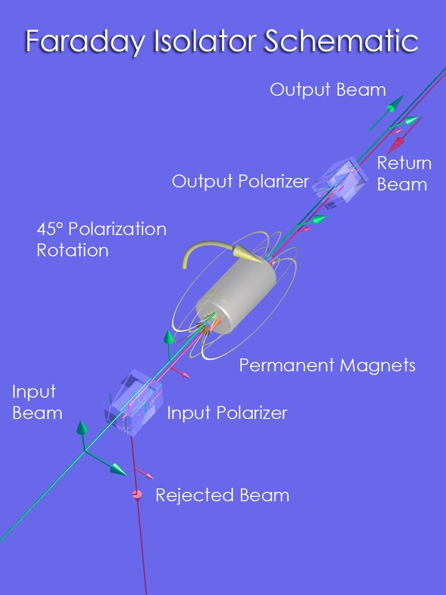
Figure 1: Operating principle of a Faraday isolator. Forward light passes the input polariser, is rotated 45° by the Faraday rotator, aligns with the output polariser and exits smoothly; when reverse light returns, its polarisation is rotated another 45° (90° in total), becoming perpendicular to the input polariser and therefore blocked.
II. Operating Principle
1. The Faraday Rotation Effect
The secret weapon of the optical isolator is the Faraday effect (Faraday Effect), also called Faraday rotation.
What is the Faraday effect? When linearly polarised light propagates through a medium and a magnetic field is applied along the direction of propagation, the plane of polarisation rotates. The rotation angle is proportional to the magnetic field strength and the length of the medium:
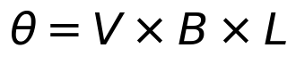
where:
- θ is the rotation angle
- V is the Verdet constant (a property of the medium material)
- B is the magnetic field strength
- L is the length of the medium
This may not sound remarkable, but the Faraday effect has one key characteristic — it is non-reciprocal.
What does “non-reciprocal” mean? If light travels from left to right and its polarisation rotates by 45 degrees, then travelling from right to left — it does not rotate back, it rotates another 45 degrees! In other words, after a round trip the polarisation has rotated 90 degrees in total.
This is different from an ordinary waveplate. With a normal half-wave plate, pass through from the left and the polarisation rotates 45 degrees; pass through from the right and it rotates back to the original direction — that is “reciprocal.” Faraday rotation is different: it depends on the direction of the magnetic field, not on the direction of light propagation — light travelling along the field rotates 45 degrees, and light travelling against the field also rotates 45 degrees (the rotations add up).
An analogy for understanding non-reciprocity: imagine walking on a moving walkway. Going with it, you are sped up; going against it, you are slowed down. Whichever direction you walk, the walkway’s “push direction” stays the same. The Faraday effect is like this moving walkway — the direction of the magnetic field is fixed, and the sense of rotation is determined by the field, not by the direction the light travels.
2. Basic Structure of a Polarisation-Sensitive Isolator
The simplest polarisation-sensitive Faraday isolator consists of three parts:
Input light → polariser P1 → Faraday rotator (45°) → polariser P2 → output light
(polariser) (at 45° to P1)
Forward transmission (light travelling from left to right)
- The incident light first passes polariser P1, becoming linearly polarised along P1’s direction
- It then passes the Faraday rotator, which rotates the polarisation direction by 45 degrees
- exactly aligning with analyser P2 (because P2 is at 45° relative to P1)
- so the light passes P2 smoothly, with very low forward loss
Reverse transmission (light travelling from right to left)
- The reflected light first passes P2 (now acting as a polariser), becoming linearly polarised along P2’s direction
- It then passes the Faraday rotator — note! because the effect is non-reciprocal, travelling in the reverse direction the polarisation still rotates 45 degrees in the same sense
- The polarisation has thus rotated 90 degrees in total, becoming perpendicular to P1’s polarisation direction
- Light polarised perpendicular to P1 cannot pass through it and is blocked
Key point: why can’t an ordinary polariser plus waveplate make an isolator? Because the waveplate is reciprocal — it rotates 45 degrees going forward and rotates back going reverse, so the light still gets through in the end. Only the non-reciprocity of the Faraday effect can achieve true one-way transmission.
3. Polarisation-Insensitive Isolators
The polarisation-sensitive isolator described above only works for light of a particular polarisation direction. What if the incident polarisation is random (as in ordinary single-mode fibre, where polarisation is usually undefined)?
This calls for a polarisation-insensitive optical isolator (Polarisation-insensitive Faraday Isolator). Regardless of the incident polarisation state, it lets forward light pass and isolates reverse light.
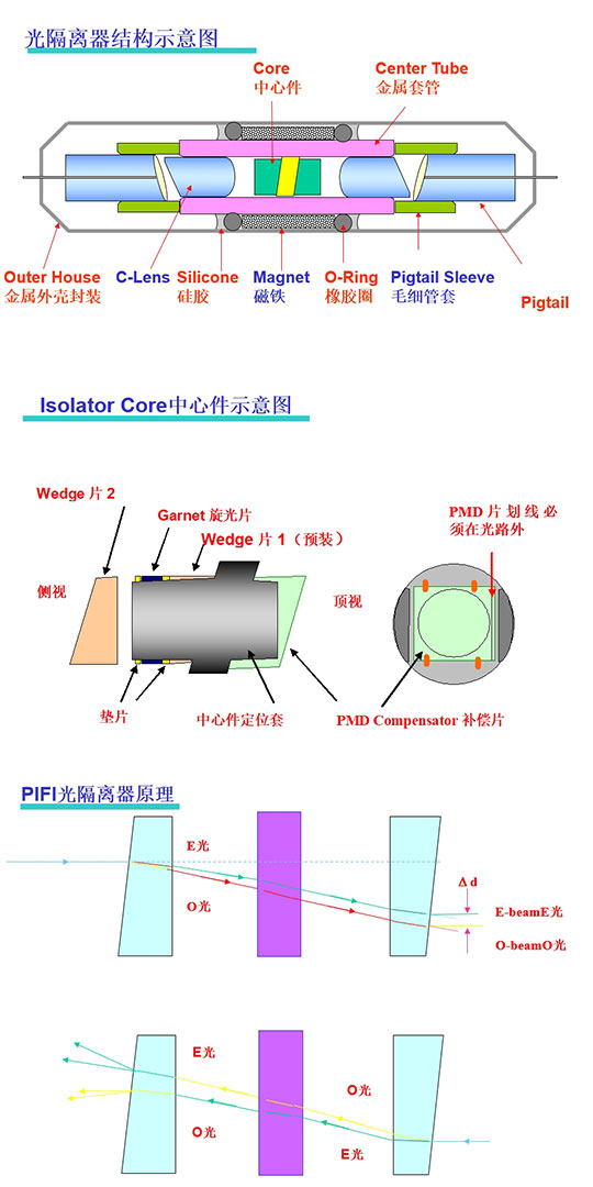
Figure 2: Structure and principle of a polarisation-insensitive Faraday isolator (PIFI). A birefringent crystal splits the incident light into two orthogonally polarised beams; after Faraday rotation they are recombined, so that any input polarisation achieves low-loss forward transmission and high reverse isolation.
Basic principle: a polarisation-splitting element (usually a birefringent wedge such as rutile TiO₂) first separates the arbitrarily polarised incident light in space into two orthogonally linearly polarised beams, lets both pass through a Faraday rotator and rotate 45 degrees, then uses a second birefringent crystal at the other end to combine the two beams into one output.
- Forward: the two split beams finally recombine and exit smoothly, with low loss
- Reverse: because of the non-reciprocity of Faraday rotation, the polarisation directions of the two beams do not match and cannot be combined; a spatial offset arises, so they cannot be coupled back into the input fibre
Note: polarisation-insensitive isolators generally do not preserve polarisation state, because there is an uncontrolled relative phase change between the two polarisation components, which depends on both temperature and wavelength.
4. Dual-Stage Isolators
If a single stage does not provide enough isolation, two isolators can be connected in series to make a dual-stage isolator (Dual-stage Isolator).
- Single-stage isolation: typically 30–40 dB
- Dual-stage isolation: up to 60 dB
- Of course, the insertion loss is also slightly higher
The two rotators of a dual-stage isolator can rotate in the same sense (total rotation 90°) or in opposite senses (total rotation 0°), requiring only a single polariser in between.
5. High-Power Optical Isolators
For high-power applications, several special issues need to be considered:
- Thermally induced depolarization: at high average power, parasitic absorption in the Faraday medium causes heating, which in turn induces thermal depolarization and reduces isolation
- Thermal lensing: parasitic absorption in the Faraday rotator produces a pronounced thermal lens, deforming the beam profile
- Laser damage: laser-induced damage can occur at high peak power, requiring a sufficiently large beam area (large aperture)
- Nonlinear self-focusing: high peak power can also lead to nonlinear self-focusing; the power threshold depends on beam radius and device length
Therefore, high-power optical isolators usually:
- use a large-aperture design
- extract the blocked light through a side window (rather than absorbing it internally)
- employ special thermal-management designs
- and the polarisers must also be of the high-power type
Commercial high-power Faraday isolators reach average powers on the order of about 100 W with little beam distortion. Kilowatt-class high-power devices are still under development. Fibre-coupled types are more limited in power, usually far below 100 W.
6. Tunable Isolators
Some tunable isolators let the user adjust the polariser angle to optimise isolation at different wavelengths (though insertion loss usually cannot be optimised at the same time). One such device can cover a very broad wavelength range, for example 500 nm to 750 nm, limited mainly by the bandwidth of the anti-reflection coatings.
7. Fibre-Based Faraday Isolators
It is also possible to draw fibre from glass with a high Verdet constant, enabling all-fibre (not merely fibre-coupled) Faraday isolators. Although current performance does not yet match that of bulk devices, they have potential value for future fibre laser sources.
III. Key Parameters and Performance Metrics
| Parameter | Meaning | Unit | Typical value |
|---|---|---|---|
| Isolation | Degree of attenuation of reverse light | dB | Single-stage 30–40 dB, dual-stage ~60 dB |
| Insertion Loss | Loss when forward light passes through | dB | 0.3~1 dB |
| Return Loss | Magnitude of end-face reflection | dB | >50 dB |
| Centre wavelength | Designed operating wavelength | nm | Must match the wavelength in use |
| Bandwidth | Wavelength range over which isolation meets the specification | nm | Depends on material and design |
| Maximum handleable power | Maximum optical power without damage | W | Free-space types can reach 100 W+ |
| Polarisation-Dependent Loss (PDL) | Difference in loss among different polarisation states | dB | A metric for polarisation-insensitive isolators |
| Clear aperture | Effective clear diameter of free-space types | mm | 3–10 mm is common |
Interpreting the Key Parameters
What does 40 dB isolation mean? The decibel is a logarithmic unit; 40 dB means the reverse light is only one ten-thousandth (10⁻⁴) of the incident light. 60 dB means one millionth. For a 1000 W high-power laser, one ten-thousandth is 0.1 W of back-reflected light — still enough to cause problems. That is why high-power and high-sensitivity applications often require higher isolation.
Why is insertion loss important? Every 1 dB of loss means roughly 20% of the optical power is wasted. For a high-power laser, loss means not only lower power but also heating — optical power turns into heat, which can damage the components.
Optimising the output polariser’s orientation requires care: if the Faraday rotation angle is not exactly 45 degrees (for example due to manufacturing tolerances or an operating wavelength deviating from the design value), the output polariser can be adjusted for maximum transmission, but isolation will then drop. You can instead optimise for isolation, but the forward insertion loss will be somewhat higher.
IV. Main Types / Classification
1. By Polarisation Characteristics
| Type | Operating principle | Typical applications | Isolation | Insertion loss |
|---|---|---|---|---|
| Polarisation-sensitive isolator | Two polarisers + Faraday rotator | Free-space systems with known polarisation | High (40–60 dB) | Low |
| Polarisation-insensitive isolator | Birefringent splitting + Faraday rotator + recombination | Fibre communications, undefined polarisation | Medium (30–40 dB) | Slightly higher |
2. By Number of Stages
- Single-stage isolator: one Faraday rotation stage plus polariser, 30–40 dB isolation, sufficient for most applications
- Dual-stage isolator: two stages in series, ~60 dB isolation, for highly sensitive applications
- Triple-stage isolator: even higher isolation (>70 dB), rarely used
3. By Package Type
- Free-space type: free-space light at both ends, for free-space optical paths
- Fibre-coupled type: fibre pigtails at both ends, for direct integration into fibre systems
- Micro-package: small form factor, for miniature laser modules
V. Typical Applications
1. Laser Output Protection
This is the most basic application of an optical isolator. Almost every laser — diode, fibre or solid-state — has an optical isolator at its output to prevent back-reflections from affecting laser stability or even causing optical damage.
In particular, for the following types of laser an isolator is all but mandatory:
- Narrow-linewidth / single-frequency lasers: back-reflections cause severe frequency instability
- High-power lasers: high back-reflected power can cause optical damage
- Gain-switched / mode-locked lasers: back-reflections affect pulse stability
2. Fibre-Optic Communication Systems
In fibre-optic communication systems, polarisation-insensitive fibre-coupled isolators are standard equipment:
- Transmitter end: protect the laser from reflections in the fibre link
- Before and after fibre amplifiers: EDFAs typically have isolators on both sides
- to prevent back-reflection interference between amplifiers and improve system stability
3. Fibre Lasers and Amplifiers
Inside fibre lasers and amplifiers, isolators are also important components:
- Amplifier chains: isolators between successive amplifier stages block reverse amplified spontaneous emission (ASE) and back-reflected light
- Ring-cavity lasers: ensure unidirectional operation
- The polarisation properties of Faraday rotators can also be used to realise linear-polarisation or nonlinear-polarisation-rotation mode locking
4. Interferometers and Optical Measurement
Various interferometers and other optical devices (including fibre-based ones) can use a Faraday circulator to separate reflected light from forward-propagating light — for example, to realise double-pass amplification of an amplifier.
5. Laser Processing Systems
In high-power laser processing (cutting, welding, marking), reflections from the workpiece are strong. High-power isolators can effectively block this back-reflected light and protect the laser.
VI. Common Misconceptions
Misconception 1: Optical isolators block light by absorbing it
Many people think an isolator “absorbs” the reverse light — but that is not the main mechanism. Most optical isolators block light through polarisation orthogonality: the reverse light’s polarisation is rotated to be perpendicular to the polariser, and is then reflected or scattered aside by the polariser (or extracted through a side window), rather than being absorbed.
Of course, real polarisers are not completely lossless; there is always some absorption. For high-power isolators, the heat generated by this absorption can become a problem.
Misconception 2: Isolation is a fixed value
Isolation is affected by many factors:
- Wavelength: away from the centre wavelength the rotation angle changes and isolation drops
- Temperature: temperature changes alter the Faraday rotation angle and affect isolation
- Angle of incidence: oblique incidence reduces isolation
- Beam divergence: beams with a large divergence angle have lower isolation
So the isolation figure quoted by manufacturers is usually a typical value under optimal conditions; in actual use it may be lower.
Misconception 3: The higher the isolation, the better
Higher isolation is of course good, but the price is higher insertion loss, higher cost and possibly narrower bandwidth. For selection, “good enough” is the goal. For an ordinary diode laser, 30 dB isolation is usually enough; a single-frequency fibre laser may need 40–50 dB; only particularly sensitive applications need more than 60 dB.
Misconception 4: Optical isolators can block all back-reflected light
An optical isolator can only block light travelling back along the original path. If reflected light does not return along the original path but reaches the laser at another angle or via another route, the isolator can do nothing. So besides adding an isolator, system design must also minimise unnecessary reflection sources — for example using angle-polished fibre ends or adding index-matching gel.
Misconception 5: Polarisation-insensitive isolators also preserve polarisation
No. A polarisation-insensitive isolator only ensures that the forward transmission efficiency is unaffected by the input polarisation state; it does not guarantee that the output polarisation state matches the input. There is an uncontrolled relative phase change between the two polarisation components, so the output polarisation state is indeterminate. If polarisation must be preserved, use polarisation-maintaining fibre together with a polarisation-sensitive isolator.
VII. Selection Advice
1. Select by Application
- Laser output protection → choose an isolator with high isolation, low loss and a suitable power rating
- Fibre-optic communication systems → choose a polarisation-insensitive fibre-coupled isolator
- Fibre amplifier systems → choose an isolator with high isolation and low PDL
- Free-space optical systems → choose a polarisation-sensitive free-space isolator (low cost, high isolation)
- High-power laser systems → choose a large-aperture, high-damage-threshold isolator with heat dissipation
2. Select by Key Specifications
- If isolation is the top priority → look at isolation; choose dual-stage if necessary
- If power efficiency matters → look at insertion loss; lower is better
- For high-power applications → check maximum handleable power and damage threshold
- For broadband applications → check operating bandwidth; a tunable type is an option
- Where polarisation is undefined → a polarisation-insensitive isolator is mandatory
3. Precautions
- Wavelength matching: the isolator’s centre wavelength must match your laser wavelength; too large a difference will drastically reduce isolation
- Power margin: choose a power rating somewhat higher than your actual use, leaving a margin
- Fibre type: for fibre-coupled isolators, check whether it is single-mode or multimode and whether the mode-field diameter matches
- Connector type: FC, SC, LC and other connectors must match your system
- Package type: free-space, fibre-coupled, micro-package, etc. — choose according to your needs
VIII. Engineering Selection Points
When actually selecting an optical isolator, beyond the basic parameters you should also pay attention to the following engineering dimensions:
8.1 Polarisation-Sensitive vs. Polarisation-Insensitive
- Polarisation-dependent isolator (Polarisation Dependent Isolator): works only for linearly polarised light of a particular direction; high isolation, simple structure, low cost. Suitable for systems with a defined polarisation state, such as inside fibre lasers and free-space laser systems.
- Polarisation-independent isolator (Polarisation Independent Isolator): isolates light of any polarisation state; a more complex structure (usually two polarising prisms + Faraday rotator + half-wave plate). Suitable for systems where the polarisation state is undefined or varies, such as fibre-optic communication systems.
8.2 High-Power Considerations
- Thermal demagnetization: at high power the magneto-optic crystal absorbs part of the laser energy, raising its temperature. Above the Curie temperature the magneto-optic material loses its ability to rotate polarisation and isolation collapses. High-power isolators need magneto-optic materials with high thermal conductivity (such as TGG crystals) and good heat-dissipation design.
- Thermal lensing: absorption of optical power in the magneto-optic crystal creates a temperature gradient that forms a thermal lens, changing the beam’s divergence angle and focusing characteristics and affecting the downstream optical path.
- Peak-power limits: in pulsed lasers, besides average power you must also check whether the peak power exceeds the damage threshold. Ultrashort pulses (femtosecond, picosecond), with their extremely high peak power, are more prone to causing damage.
8.3 Dispersion Issues with Ultrafast Lasers
Ultrafast lasers such as femtosecond and picosecond systems have extremely short pulse durations and very broad spectra. The magneto-optic crystal and other components in an optical isolator introduce group-delay dispersion (GDD), broadening the pulses. For dispersion-sensitive ultrafast systems, choose a low-dispersion isolator or provide dispersion compensation in the system.
💡 Quick selection guide: checklist of key parameters to confirm when choosing an optical isolator: ① operating wavelength ② isolation requirement ③ maximum insertion loss ④ polarisation-sensitive / insensitive ⑤ power level (CW / pulsed, average / peak) ⑥ clear aperture ⑦ operating temperature range ⑧ whether low dispersion is required
VIII. Recommended Reading
- RP Photonics: Optical Isolators (original)
- RP Photonics: Faraday Isolators (original)
- What Is a Waveplate? The Functions of Quarter-Wave and Half-Wave Plates
- What Is a Fibre Laser? Why It Became Mainstream
- What Is a Diode Laser? Everywhere from Optical Communications to Material Processing
- Polarisation Rotators (Faraday Rotators / Half-Wave Plates / Liquid Crystal — Three Routes, Principles and Selection)
IX. References
- RP Photonics Encyclopedia – Optical Isolators (https://www.rp-photonics.com/optical_isolators.html)
- RP Photonics Encyclopedia – Faraday Isolators (https://www.rp-photonics.com/faraday_isolators.html)
- RP Photonics Encyclopedia – Faraday Rotators (https://www.rp-photonics.com/faraday_rotators.html)
- RP Photonics Buyer’s Guide for Faraday Isolators
Leave a Reply