


Fibre Coupling Technology and Coupling Efficiency
I. Overview
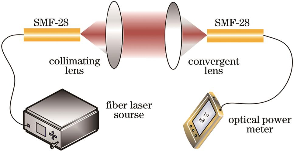
Anyone working in optics has probably had the painful experience of “coupling into fibre” — you spend ages aligning the fibre, the light simply will not go in, and just when a little gets in, the slightest hand movement loses it again. Fibre coupling sounds simple (isn’t it just shooting light into a fibre?), but in practice you learn how hard it really is.
Fibre coupling is the process of efficiently injecting a laser beam (or other light source) into a fibre’s core. It may look as simple as “alignment,” but it actually involves a host of issues — beam quality, numerical-aperture matching, mode-field matching, alignment precision. The achievable coupling efficiency directly determines the optical-power utilisation of the whole system.
Why is coupling efficiency so important? Example: you have a 10 W laser, but after coupling into fibre only 5 W remains — 50% efficiency, half the power wasted. If you raise coupling efficiency to 80%, it is like gaining 3 W out of nowhere, far more economical than switching to a higher-power laser.
A vivid analogy: fibre coupling is like pouring water into a narrow-necked bottle. The mouth is tiny (fibre core diameter only a few to tens of micrometres); you must align with the bottle mouth, keep the water stream from spreading too much (NA must match), and make sure the stream is straight (low aberration). Get any part wrong and the water spills outside.
RP Photonics’ content on Fibre Joints, Mode Matching and Fibre-Coupled Diode Lasers together form the knowledge framework of fibre-coupling technology.
Core goals of fibre coupling:
- High coupling efficiency (as much light as possible into the fibre)
- High stability (after alignment, not easily shifted by environmental effects)
- Low return loss (reduced end-face reflection)
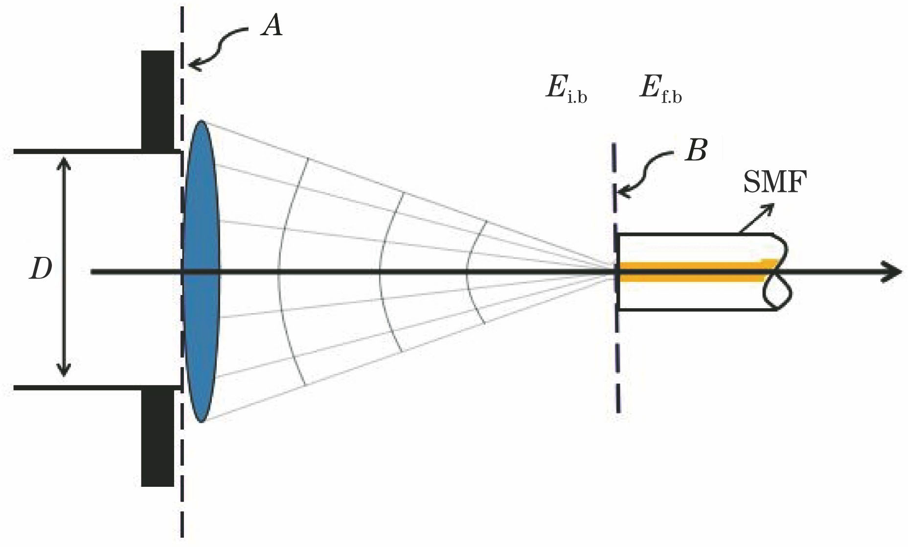
Figure 1: schematic of free-space light focused by a lens and coupled into a single-mode fibre. Coupling efficiency depends on how well the incident beam’s mode-field distribution matches the fibre’s eigenmode, including spot size, position and wavefront curvature.
II. Working principles
1. What kind of light can a fibre accept?
To understand how to couple light into a fibre efficiently, you must first know what kind of light a fibre “eats.”
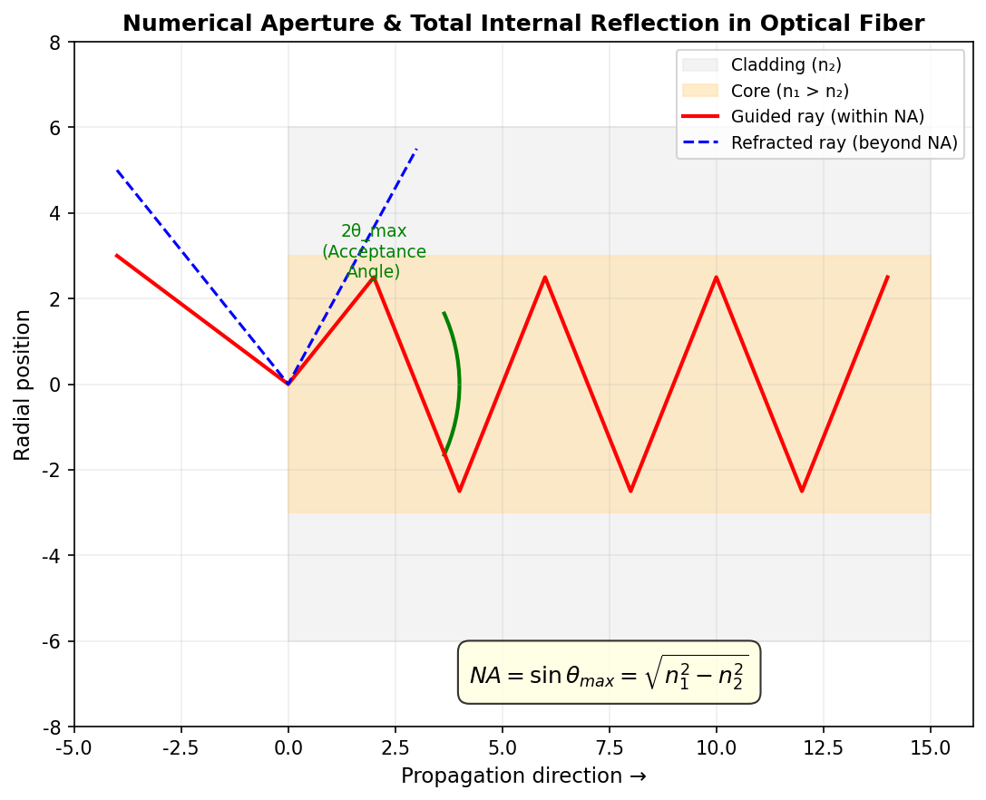
A fibre guides light by total internal reflection. Once light enters through the end face, if it satisfies the total-reflection condition at the core-cladding interface, it propagates down the fibre.
Numerical aperture (NA) is the core parameter describing a fibre’s light-gathering ability:

where:
- n₀ is the refractive index of the incident medium (about 1 for air)
- θ_max is the maximum acceptance angle (half angle) the fibre can accept
- n₁ is the core refractive index
- n₂ is the cladding refractive index
Physical meaning: the larger the NA, the larger the fibre’s “acceptance angle” and the easier it is to couple light in.
But for single-mode fibre, satisfying the NA condition alone is not enough — mode-field matching matters more.
2. Mode matching: the core of single-mode fibre coupling
According to RP Photonics’ definition of mode matching, it means precisely matching a laser beam’s electric-field distribution spatially to another beam (or waveguide mode, resonator mode) to achieve efficient coupling.
Mode matching requires not only the intensity distribution (spot shape and size) to match, but also the phase distribution (wavefront). If two beams’ complex amplitude distributions match well in one plane, they will remain matched in subsequent propagation.
Mathematical expression of coupling efficiency (overlap integral):
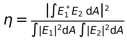
where E_1 and E_2 are the complex amplitudes of the two optical fields (e.g. incident beam and fibre mode), and the integral is taken over the whole beam cross-section. This formula applies both to the scalar case (assuming uniform polarisation) and the vector case.
The physical essence of coupling efficiency: the more “alike” the incident light’s energy distribution and the fibre mode’s energy distribution, the higher the fraction that couples in. Not only must the shape be alike, the phase must also be right — if the incident wavefront is curved, even with the correct size the coupling efficiency will not improve.
3. Coupling-efficiency formula for single-mode fibre butt coupling
For single-mode fibre butt coupling under the Gaussian approximation, the effects of lateral offset and mode-field radius mismatch can be calculated with:

where w_1 and w_2 are the mode-field radii of the two fibres and  is the lateral offset.
Effect of angular deviation (e.g. from a non-perpendicular cleave) on coupling efficiency:
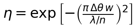
This shows that for large-mode-field fibres, angular alignment is even more critical.
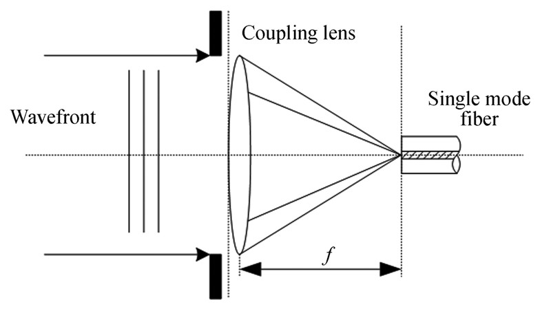
Figure 2: schematic of collimated light focused by a coupling lens onto a single-mode fibre end face. The coupling lens converges the parallel light onto the fibre core; the focal position and size must precisely match the fibre’s mode-field diameter.
4. Multimode vs single-mode fibre coupling
Multimode fibre coupling
Multimode fibre alignment tolerance is much looser, especially for large-core multimode fibre. As long as the second fibre’s (receiving end) core diameter and NA are greater than or equal to the first, relatively high coupling efficiency is achievable.
But note: even in a case that seems lossless (e.g. the output fibre has a larger core and the same NA), coupling loss can still occur in practice — because changing core diameter changes the mode distribution, the incident fibre’s modes cannot fully convert to the output fibre’s guided modes, and part of the light enters the cladding. Moreover, this loss varies by mode and depends on core mismatch in a complex way.
In summary: multimode fibre coupling mainly depends on NA and core-diameter matching, but accurate loss calculation requires numerical simulation and cannot be estimated simply by geometrical optics.
Single-mode fibre coupling
Single-mode fibre is completely different. Coupling efficiency is independent of propagation direction (reciprocal), and low loss is achieved only when all of the following hold:
- Similar mode-field shapes (especially effective mode-field area)
- Very precise lateral and angular alignment
5. Several fibre-connection methods
According to RP Photonics’ classification, fibre-end connections mainly use the following technologies:
(1) Fusion splicing
Fuses two fibres together by heating (usually with an electric arc).
- Advantages: permanent connection, very stable, extremely low loss (typically 0.01–0.1 dB)
- Disadvantages: not detachable, requires specialised equipment
(2) Mechanical splices
Uses a precision alignment device to bring two fibre end faces together, usually with index-matching gel or epoxy to reduce reflection loss.
- Advantages: fast, detachable, low initial cost
- Disadvantages: higher loss (about 0.5 dB), less stable than fusion, higher unit cost
(3) Fibre connectors
Used where frequent mating/unmating is needed. Common types include FC, SC, LC (for single-mode) and ST (for multimode).
- Advantages: convenient mating, highly standardised
- Disadvantages: loss similar to mechanical splices (~0.5 dB), lower stability
(4) Free-space coupling
Uses a lens to focus a beam onto the fibre end face.
- Advantages: the fibre end face can be kept at a distance (less easily damaged), efficient coupling is possible between fibres of different mode-field areas, and other optical elements (filters, isolators) can be inserted in between
- Disadvantages: needs precise alignment and a stable optical structure, sensitive to dust, with Fresnel reflection at the end face
6. Importance of end-face preparation
Regardless of the connection method, fibre end-face preparation is critical.
- Perpendicular end face: most common; the optical axis coincides with the fibre axis, simple alignment
- Angle cleave: the end face is tilted from perpendicular; the benefit is that reflection at the glass-air interface does not couple back into the fibre mode (if the angle is large enough), important for laser-source stability
III. Key parameters and performance metrics
| Parameter | Meaning | Unit | Description |
|---|---|---|---|
| Coupling efficiency | Power entering the fibre / total incident power | % | Higher is better |
| Insertion loss | -10×log₁₀(coupling efficiency) | dB | Lower is better |
| Return loss | Logarithm of reflected optical power | dB | Higher is better |
| Mode-field diameter (MFD) | Mode-field size of a single-mode fibre | μm | Matching is critical |
| Numerical aperture (NA) | Fibre’s light-gathering ability | Dimensionless | Determines angular tolerance |
| Lateral alignment tolerance | Lateral offset at which coupling efficiency drops by a given amount | μm | Smaller means more sensitive |
| Angular alignment tolerance | Angular deviation at which coupling efficiency drops by a given amount | °, mrad | Large mode field is more sensitive |
Reference coupling efficiency (single-mode fibre butt coupling)
| Spot / mode-field ratio | Coupling efficiency (ideal alignment) | Insertion loss |
|---|---|---|
| 0.5 | ~82% | ~0.86 dB |
| 0.7 | ~96% | ~0.18 dB |
| 0.8 | ~99% | ~0.04 dB |
| 1.0 | 100% | 0 dB |
| 1.2 | ~99% | ~0.04 dB |
| 1.5 | ~90% | ~0.46 dB |
| 2.0 | ~70% | ~1.55 dB |
As can be seen, with the ratio between 0.7 and 1.5, coupling efficiency is still good (over 90%). But deviating too far causes a marked efficiency drop.
IV. Main types / classification
1. By coupling method
| Coupling method | Principle | Efficiency | Suitable scenarios |
|---|---|---|---|
| Direct coupling (free space directly on end face) | Beam shines directly onto the fibre end face | Low (especially single-mode) | Multimode fibre, low-cost cases |
| Lens coupling | Lens focuses onto the end face, controlling spot size and angle | High (80–98%) | Single-mode fibre, high-efficiency requirements |
| Fibre fusion splicing | Arc melting joins two fibres | Very high (97–99.9%) | Permanently connected fibre systems |
| Fibre connectors | Standardised plug mating | Medium-high (~90%) | Cases needing mating/unmating |
| Mechanical splice | Precision V-groove + index-matching gel | Medium (~89%, 0.5 dB) | Temporary connections, field work |
2. By fibre type
- Multimode fibre coupling: NA matching is key, large alignment tolerance, high coupling efficiency easy to achieve
- Single-mode fibre coupling: mode-field matching is core, high alignment precision required, needs precise optical design
- Polarisation-maintaining fibre coupling: besides mode field and position, polarisation direction alignment matters
- Large-mode-area (LMA) fibre coupling: large mode-field diameter, relatively easy to couple, but usually used at high power
3. Common coupling-lens types
- Aspheric lens: a single lens with small spherical aberration, high coupling efficiency, the most common
- C-lens: a short cylindrical lens with one spherical and one flat end, often used in fibre collimators
- GRIN lens (G-lens, self-focusing lens): focuses by a graded refractive index, flat end faces, easy to bond to fibres
- Ball lens: small size, but relatively large aberrations
- Lens group: multiple lenses combined, for demanding applications
V. Typical application scenarios
1. Laser fibre-coupled output
Many lasers (diode lasers, solid-state lasers) output free-space light that must be coupled into a fibre for delivery or use. Fibre-coupled-output lasers are convenient and have good beam quality, the first choice for many applications.
Especially fibre-coupled diode lasers (Fibre Coupled Diode Lasers), which couple diode laser light into a fibre, combining the diode’s high efficiency with the convenience of fibre output — the standard scheme for pumping fibre lasers.
2. Optical-fibre communication systems
In optical communication, the laser’s light must be coupled into the transmission fibre and the received light into the detector. In the whole link’s loss budget, coupling loss is a large part. Raising coupling efficiency effectively extends transmission distance.
3. Fibre amplifiers and fibre lasers
In fibre lasers and amplifiers, pump light must be coupled into the gain fibre and signal light coupled between fibre components. Coupling efficiency directly affects the system’s optical-to-optical conversion efficiency and output power.
4. Fibre sensing
Fibre sensors (interferometric, grating types etc.) usually need to couple source light into the sensing fibre and couple the signal light back out. Coupling efficiency affects the system’s signal-to-noise ratio and measurement sensitivity.
5. Laser processing
In high-power laser processing, fibre delivery is a common approach — the laser light is coupled into a delivery fibre whose other end connects to the processing head. Coupling at high power must not only be efficient but also withstand high power to avoid end-face damage.
6. Biomedical optics
In bioimaging (two-photon microscopy, OCT), laser medicine and similar applications, laser light often needs to be coupled into a fibre probe to reach inside biological tissue.
VI. Common myths
Myth 1: Low coupling efficiency means it is not aligned
Many people, seeing low coupling efficiency, keep readjusting position — but alignment is only one factor. Low efficiency can have many causes:
- Mode-field mismatch (wrong spot size)
- NA mismatch (focusing angle too large)
- Excessive lens aberration
- Dirty or damaged fibre end face
- Poor beam quality (high M²)
- Wavefront mismatch (e.g. incident light has astigmatism)
The correct troubleshooting order: first confirm the optical design is sound (NA and mode field matched), then check end-face quality, and only finally do fine alignment.
Myth 2: More lenses mean higher coupling efficiency
Not necessarily. More lenses may correct aberration better, but each extra lens adds two reflection surfaces — about 4% reflection at each uncoated interface, a notable loss. More lenses also make assembly harder and accumulate alignment errors.
In fact, for most applications, a single high-quality aspheric lens is enough, achieving 80–90% or better coupling efficiency.
Myth 3: A fibre with larger NA is easier to couple
For multimode fibre, yes, larger NA is easier. But for single-mode fibre, NA and mode-field diameter are related — a single-mode fibre with larger NA usually has a smaller mode-field diameter, requiring an even smaller focused spot and making alignment harder.
Moreover, a fibre with too large NA has greater bending loss, unfavorable for long-distance transmission.
Myth 4: Higher coupling efficiency means larger alignment tolerance
Quite the opposite — the higher the coupling efficiency, the smaller the alignment tolerance usually is. Like shooting: to hit a bullseye you must aim very precisely, a slight deviation misses; if just hitting the target is enough, the aiming requirement is much looser.
So in coupling you must trade off efficiency against stability. If the system has strong vibration or temperature variation, you may need to sacrifice some efficiency for a larger alignment tolerance.
Myth 5: Multimode fibre coupling can be calculated accurately by geometrical optics
RP Photonics explicitly states: reliably estimating multimode fibre coupling loss is very difficult. Because coupling loss depends on how optical power is distributed among modes, and wave optics brings surprising behaviours — e.g. when the output fibre has a larger core and the same NA, you might expect zero loss, but in practice there is still loss because the mode shapes changed. Accurate calculation needs professional numerical simulation software.
VII. Selection advice
1. By fibre type
- Multimode fibre → NA matching is key; choose a focusing lens with suitable NA, coupling efficiency is usually fairly high
- Single-mode fibre → mode-field matching is key; precisely control focused-spot size, use an aspheric or GRIN lens
- Polarisation-maintaining fibre → besides the above, mind polarisation-direction alignment
- Large-mode-area fibre (LMA) → large mode-field diameter, relatively easy to couple, but mind power handling
2. By application requirement
- Pursue highest efficiency → use an aspheric lens + precision stage, AR-coat the end face
- Pursue stability → use a fibre-coupled-output laser (coupled at the factory), or fusion splicing
- Limited space → choose micro lenses (G-lens, C-lens, ball lens)
- High-power applications → mind end-face damage threshold, may need end-face coating or special treatment
- Mass production → choose a mature coupling scheme, consider the cost of automated alignment equipment
3. Practical tips to improve coupling efficiency
- Coarse then fine: coarsely align by eye or low-power microscope, then fine-adjust with power-meter feedback
- Three-axis stage: at least precise adjustment in X, Y and Z
- Angle adjustment: better if an angular stage is available, to optimise angular alignment
- Clean the end face: always wipe the fibre end face clean before coupling, dust matters a lot
- Check end-face quality: use a fibre end-face inspector to see if the face is flat and scratch-free
- AR-coat the end face: reduces about 4% Fresnel reflection
- Optimise lens distance: move the lens back and forth to find the best coupling point
VIII. Recommended reading
- What is Fibre Coupling? How to Efficiently Inject Laser Light into a Fibre
- What is Optical Fibre? How Light Travels Thousands of Miles in a Glass Strand
- What is Single-Mode Fibre? Why Communication Uses It
- What is a Fused Fibre Coupler? How Two Fibres Split Light
- What are Laser Modes? Transverse and Longitudinal Modes Explained
- What is an Optical Power Meter? How to Accurately Measure Laser Power
- What is Beam Profiling? Intensity Distribution Across a Laser’s Cross-Section
Leave a Reply