


What Is Single-Mode Fibre? Why Communication Networks Use It
A single-mode fibre supports only one spatial mode, so the reach and bandwidth ceiling of single-mode fibre are dictated by modal dispersion. The sections below explain the guiding mechanism, then the key parameters, the main types and the engineering applications.
Table of contents
- 1. What is single-mode fibre? Getting the core concept straight
- 2. Working principle: how single-mode fibre is achieved
- 3. Key parameters: reading the specifications of single-mode fibre
- 4. Main types: what kinds of single-mode fibre are there
- 5. Applications: where single-mode fibre is used
- 6. Common misconceptions: pitfalls to avoid
1. Core concept: what is single-mode fibre?
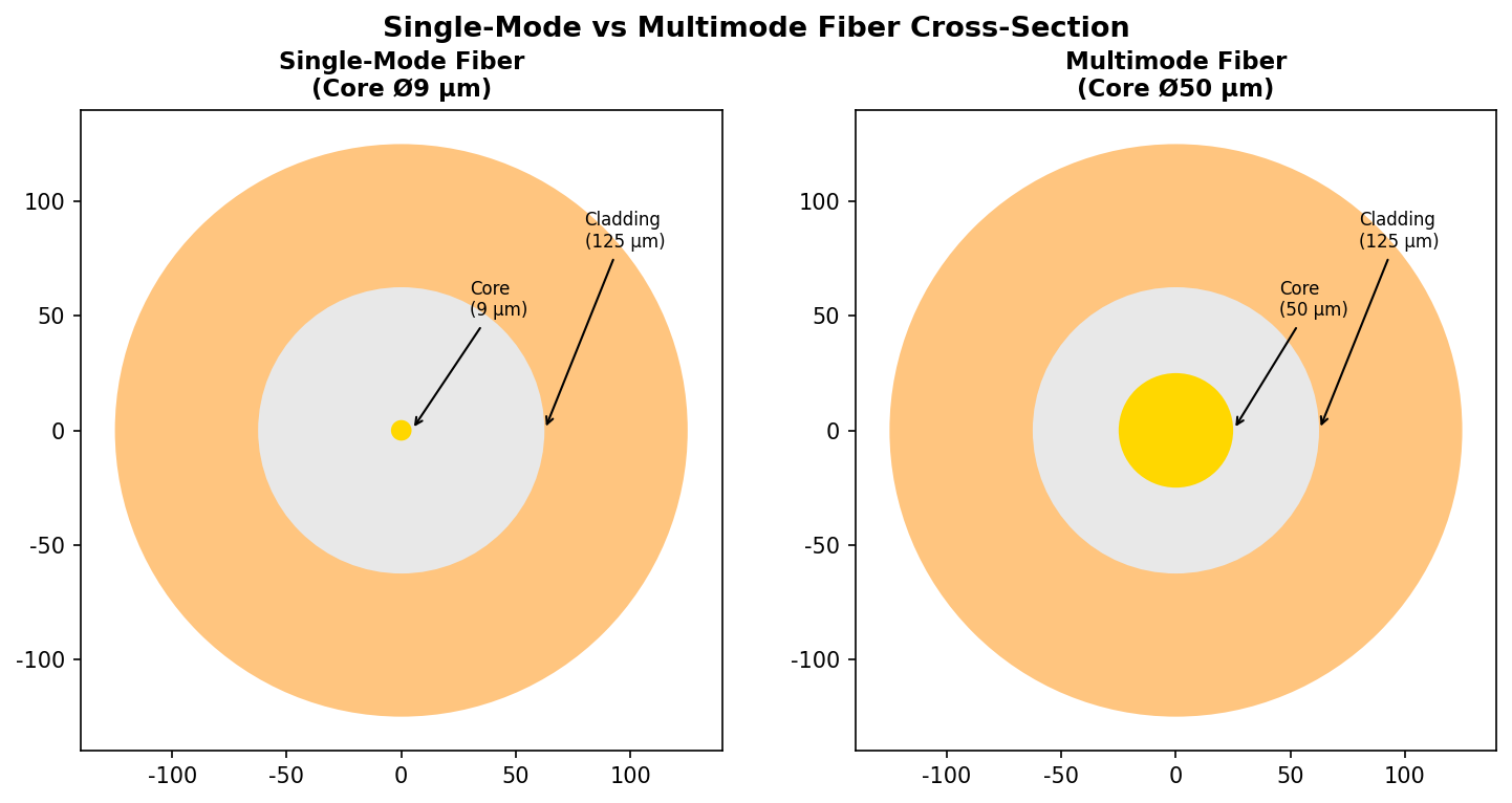
Single-mode fibre (SMF) is a fibre that supports only one guided mode (the fundamental mode LP₀₁) in each polarisation direction at a given operating wavelength. Its defining feature is a very small core diameter (typically a few micrometres), which prevents higher-order modes from propagating so that only the fundamental mode is guided stably. The output beam of a single-mode fibre has a fixed intensity distribution (close to Gaussian) that does not depend on how the light was coupled in: whatever the coupling geometry, once the light is guided, the output mode shape is the same and only the coupling efficiency changes. This single-mode propagation removes intermodal dispersion, which is what makes high-speed, long-distance optical communication possible.
2. Working principle: how is single-mode fibre achieved?


The single-mode condition V < 2.405 is the key criterion in fibre optics. When the normalised frequency V falls below 2.405, higher-order modes (LP₁₁ and above) can no longer be guided stably in the core, and only the fundamental mode LP₀₁ propagates. This is the operating condition of single-mode fibre.
💡 What V = 2.405 physically means
2.405 is the first zero of the zeroth-order Bessel function J₀(x). When the V parameter equals exactly 2.405, the normalised transverse propagation constant of the LP₁₁ mode goes to zero and the mode sits at cutoff. Below this value the higher-order modes become leaky modes and can no longer be guided stably in the core.
The operating principle of single-mode fibre rests on the mode cutoff condition. For a step-index fibre, the parameter that decides whether transmission is single-mode is the V number (normalised frequency), given by V = (2πa/λ) × NA, where a is the core radius, λ the wavelength and NA the numerical aperture. When the V number is below about 2.405 the fibre supports only the fundamental mode LP₀₁; higher-order modes such as LP₁₁ and LP₀₂ are all at cutoff and cannot be guided effectively.
Single-mode transmission has an important wavelength threshold, the cutoff wavelength. When the operating wavelength is shorter than the cutoff wavelength, the V number rises, the fibre starts to support several modes, and transmission becomes multimode. The transition is very sharp: near the cutoff wavelength a small change in wavelength flips the output spot from the stable Gaussian shape of single-mode operation to the complex interference pattern of multimode operation. On the long-wavelength side the limit usually comes from increasing bending loss or from material absorption.
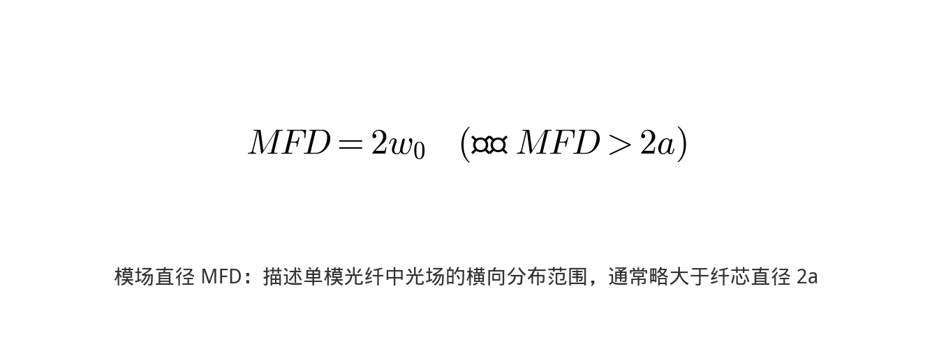
The mode field diameter (MFD) of the light emerging from a single-mode fibre is usually slightly larger than the core diameter, because part of the optical field “leaks” into the cladding. This is an inevitable consequence of wave optics — light cannot be confined entirely within a geometric boundary. Standard single-mode fibre such as Corning SMF-28 has a mode field diameter of about 10.4 μm at 1550 nm.
3. Key parameters: reading the specifications of single-mode fibre
Mode field diameter (MFD) vs core diameter
The mode field diameter (Mode Field Diameter, MFD) is a parameter specific to single-mode fibre; it describes how widely the fundamental-mode field is distributed across the cross-section. Unlike in multimode fibre, the optical field in single-mode fibre is not confined entirely to the core: a substantial fraction of the energy propagates in the cladding as an evanescent field.
Therefore, the MFD is always larger than the core diameter. Take standard single-mode fibre (SMF-28) as an example: at 1550 nm the core diameter is about 8.2 μm while the MFD is about 10.4 μm. The longer the wavelength, the larger the MFD and the greater the fraction of energy carried in the cladding.
💡 Why the MFD matters more than the core diameter
In fibre coupling and fusion splicing, it is the matching of the mode field diameters that determines the coupling efficiency, not the core diameters. Two single-mode fibres with the same core diameter but different MFDs (for instance because they work at different wavelengths) will also show different splice losses.
Cutoff wavelength
The cutoff wavelength (cutoff wavelength) is another key parameter of single-mode fibre: the critical wavelength at which the fibre switches from multimode to single-mode transmission. When the operating wavelength is longer than the cutoff wavelength the fibre operates in the single-mode state; when it is shorter, higher-order modes appear.
The cutoff wavelength of standard single-mode fibre usually falls in the 1100–1280 nm range, which ensures single-mode transmission in both the 1310 nm and 1550 nm communication windows. Near the cutoff wavelength the mode field diameter changes abruptly (it jumps up), which is also the experimental criterion for deciding whether a fibre is operating in the single-mode state.
Core formulas
Single-mode condition: when the normalised frequency V < 2.405, the fibre supports only the fundamental mode LP₀₁:
V = (2πa/λ) × NA < 2.405
Cutoff wavelength: the wavelength corresponding to V = 2.405 is the cutoff wavelength λc:
λc = 2πa · NA / 2.405
When the operating wavelength λ > λc the fibre operates in the single-mode state; when λ < λc, higher-order modes begin to appear.
Mode field diameter (MFD): the optical field in single-mode fibre is not confined entirely to the core, part of it extends into the cladding. The Marcuse formula gives the common approximation:
MFD ≈ 2a × (0.65 + 1.619/V^(3/2) + 2.879/V⁶)
For standard SMF-28 fibre (core diameter about 8.2 μm), the MFD is about 10.4 μm at 1550 nm.
Reading the key parameters is the starting point for evaluating single-mode fibre performance. The table below sets out the main specifications and what they mean:
| Parameter | Meaning | Engineering significance |
|---|---|---|
| Cutoff wavelength | The critical wavelength at which the fibre changes from single-mode to multimode; the operating wavelength must be above this value to guarantee single-mode transmission | The shortest wavelength for single-mode operation; below it the fibre becomes multimode |
| Mode field diameter (MFD) | The effective width of the transverse distribution of the fundamental-mode field, the key parameter for fibre coupling and connection | The effective width of the optical field; it affects splice loss and coupling efficiency and is slightly larger than the core diameter |
| Core diameter | About 8–10 μm for standard single-mode fibre | Sets the single-mode operating condition and the mode field size; about 8–10 μm for standard SMF |
| Numerical aperture (NA) | Typically about 0.14 for standard single-mode fibre | Sets the acceptance angle and coupling tolerance; typical values 0.10–0.14 |
| V number | Normalised frequency; the single-mode condition is V < 2.405 | The key figure for assessing single-mode performance; it sets the number of modes the fibre supports and therefore the usable bandwidth, so it has to be checked against the operating wavelength in every design |
| Transmission loss | Typically below 0.25 dB/km at 1550 nm | Sets the maximum transmission distance; as low as 0.2 dB/km at 1550 nm |
| Dispersion | Combines material dispersion and waveguide dispersion; it determines how much the optical pulse broadens | It broadens the optical pulse during transmission and limits the bit rate and reach of the system, the main constraint on high-speed long-distance fibre communication links |
| Bending loss sensitivity | Single-mode fibre is more sensitive to bending, especially large-mode-area fibre | It directly determines the maximum unrepeatered distance and the optical power budget of a link, which makes it a core parameter in fibre evaluation and system design |
Dispersion types and the zero-dispersion wavelength
The dispersion of single-mode fibre falls mainly into three categories:
① Material dispersion: caused by the wavelength dependence of the refractive index of silica, so light of different wavelengths travels at different speeds in the material.
② Waveguide dispersion: caused by the way the field energy is distributed between core and cladding changing with wavelength.
③ Polarisation mode dispersion (PMD): arises because slight asymmetries in the fibre make the two orthogonal polarisation modes travel at slightly different speeds.

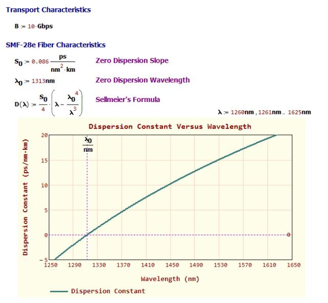
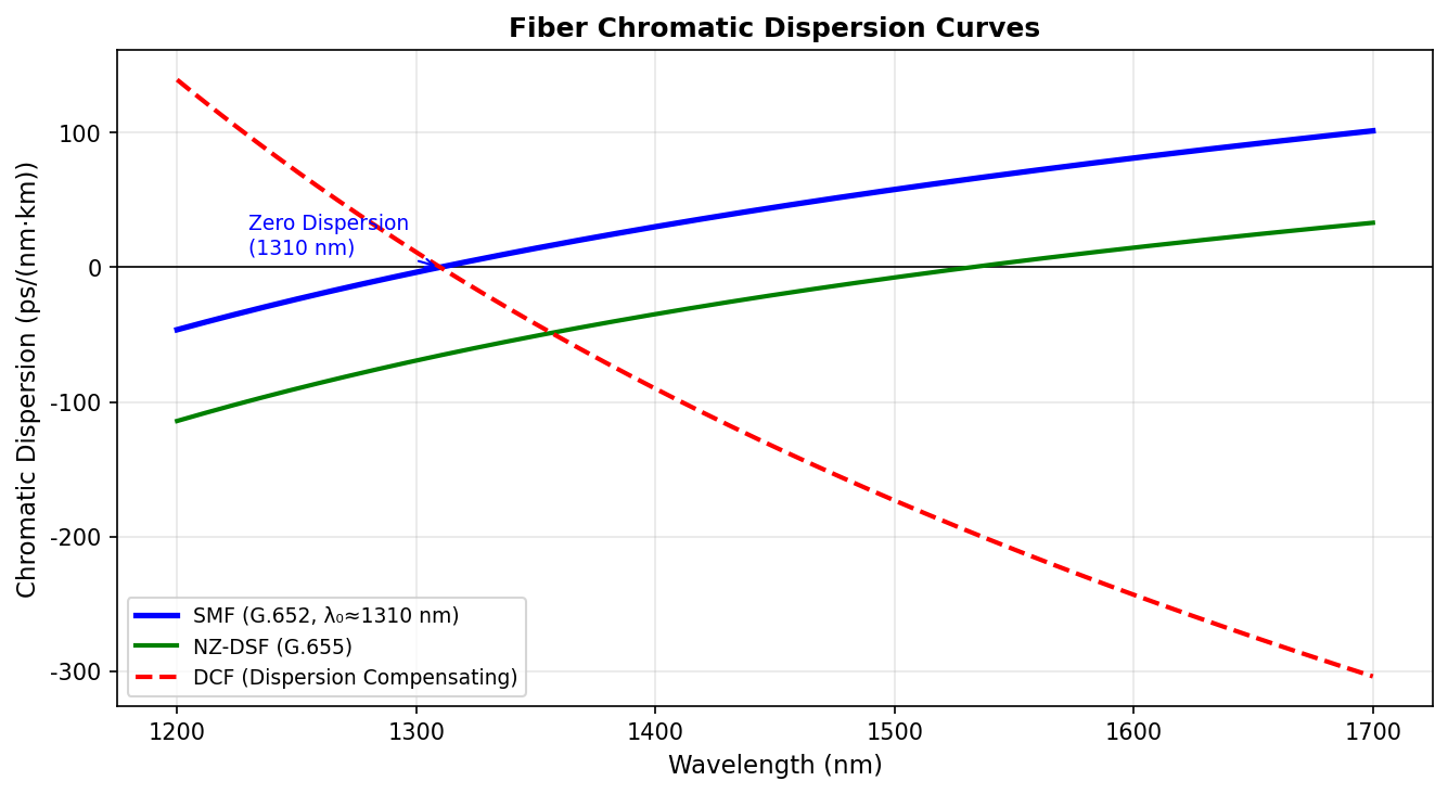
The sum of material dispersion and waveguide dispersion is called chromatic dispersion. For standard single-mode fibre (G.652) the zero-dispersion wavelength lies near 1310 nm, where material dispersion and waveguide dispersion cancel each other and the total dispersion is zero. The lowest-loss window, by contrast, is at 1550 nm — the starting point for the design of dispersion-shifted fibre (G.653) and non-zero dispersion-shifted fibre (G.655).
4. Main types: what kinds of single-mode fibre are there?
ITU-T classification of single-mode fibre standards
- G.652: standard single-mode fibre (such as Corning SMF-28); zero-dispersion wavelength around 1310 nm and dispersion of about 17 ps/(nm·km) at 1550 nm. By far the most widely used
- G.653: dispersion-shifted fibre (DSF); the zero-dispersion wavelength is moved to 1550 nm, which suits long-distance single-channel transmission, but four-wave mixing limits its use in WDM systems
- G.654: cutoff-wavelength-shifted fibre; low loss and large effective area at 1550 nm, for submarine cables and ultra-long-haul transmission
- G.655: non-zero dispersion-shifted fibre (NZ-DSF); a small amount of dispersion (2–6 ps/(nm·km)) is retained at 1550 nm to suppress nonlinear effects, which suits DWDM
- G.656: wideband non-zero dispersion fibre covering the S, C and L bands, for wideband WDM systems
- G.657: bend-insensitive fibre, split into class A and class B; class B has extremely low bending loss and is used for FTTH drop wiring
There are several ways to classify single-mode fibre, and each dimension helps you understand its characteristics from a different angle. The most common classifications are introduced below:
By ITU standard
G.652
Standard single-mode fibre: the conventional type used most widely, with the zero-dispersion point near 1310 nm
G.653
Dispersion-shifted fibre: the zero-dispersion point is moved to the 1550 nm window, which suits long-distance single-channel transmission
G.654
Cutoff-wavelength-shifted fibre: lower loss, for ultra-long-distance links such as submarine cables
G.655
Non-zero dispersion-shifted fibre: a small amount of dispersion is kept in the 1550 nm window to suppress four-wave mixing, which suits WDM systems
G.656
Wideband non-zero dispersion fibre: supports a wider range of operating wavelengths
G.657
Bend-insensitive single-mode fibre: for access networks and other places with frequent bending
By special design
Large mode area (LMA) single-mode fibre
A much larger mode area (tens to hundreds of μm²) allows higher optical power handling, which makes it suitable for high-power fibre lasers
Effectively single-mode fibre
Although the geometry supports several modes, the design makes the higher-order modes highly lossy, so in practice only the fundamental mode is transmitted
Endlessly single-mode photonic crystal fibre
Maintains single-mode transmission over an extremely wide wavelength range
Polarisation-maintaining single-mode fibre
Has high birefringence and preserves the input polarisation state
Dispersion-engineered fibre
Tailors the dispersion characteristics with a special refractive index profile
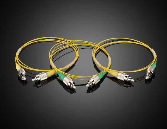
5. Applications: where is single-mode fibre used?
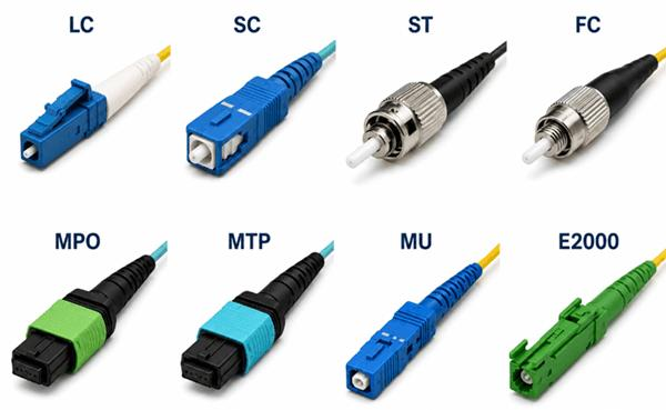
The applications of single-mode fibre span several fields; the main directions are:
- Long-distance fibre communication: single-mode fibre is the core of the global backbone network; free of intermodal dispersion and low in loss, it carries Tbit/s-class data over thousands of kilometres
- Fibre lasers and amplifiers: the beam produced by single-mode active fibre (ytterbium-doped, erbium-doped and the like) is close to the diffraction limit with M² ≈ 1, which makes it the gain medium of high-beam-quality fibre lasers
- Fibre sensing: many high-precision fibre sensors (fibre optic gyroscopes, interferometric sensors) depend on the modal stability of single-mode fibre
- Nonlinear optical devices: the high intensity and long interaction length in single-mode fibre make nonlinear effects strong, which is exploited for supercontinuum generation, Raman amplification, optical frequency combs and more
- Precision optical measurement: the stable spatial mode of the single-mode fibre output is used for beam quality improvement (spatial filtering) and optical coherence tomography (OCT), among others
- Data centre interconnect: medium- and long-range links between data centres normally run on single-mode fibre
👉 Want to see more real application cases? Visit the application case page of Soar Laser, or contact our technical team directly for professional advice.
6. Common misconceptions
Misconception 1: single-mode fibre has only one mode
Strictly speaking, single-mode fibre has two orthogonal polarisation modes (LP₀₁ˣ and LP₀₁ʸ). In an ideally circular fibre these modes are degenerate, but real fibres have imperfections (non-circularity, uneven stress) that produce birefringence, so the propagation constants of the two polarisation modes differ slightly. This is the origin of polarisation mode dispersion (PMD). Polarisation-maintaining fibre deliberately introduces strong birefringence to control the polarisation state.
Misconception 2: the light is completely confined to the core
The optical field is not confined entirely to the core. According to wave optics, part of the mode field “leaks” into the cladding and forms an evanescent tail. This is why the mode field diameter (MFD) is always slightly larger than the core diameter — the core of a standard single-mode fibre is about 8.2 μm, while the MFD at 1550 nm is about 10.4 μm. Although the field in the cladding decays exponentially in intensity, it still has an important effect on splice loss, coupling efficiency and bending loss.
Misconception 3: single-mode fibre is single-mode at any wavelength
Single-mode transmission has a wavelength threshold, the cutoff wavelength. When the operating wavelength is shorter than the cutoff wavelength, the V number rises above 2.405 and the fibre starts to support higher-order modes such as LP₁₁, becoming a multimode fibre. The same fibre may therefore be single-mode at 1550 nm and multimode at 850 nm. When selecting single-mode fibre you must confirm that the cutoff wavelength lies below the operating wavelength.
Misconception 4: the zero-dispersion wavelength is the lowest-loss wavelength
These are two completely different concepts. For standard single-mode fibre (G.652) the zero-dispersion wavelength is near 1310 nm, where material dispersion and waveguide dispersion cancel and the total dispersion is zero, whereas the lowest-loss window is near 1550 nm (about 0.2 dB/km). Dispersion-shifted fibre (G.653) reaches the 1550 nm low-loss window by adjusting the waveguide dispersion to move the zero-dispersion wavelength, but this brings nonlinear problems such as four-wave mixing, which is why it is not the first choice in DWDM systems.
7. Recommended reading
- What is optical fibre? How light travels thousands of kilometres in a glass thread
- What is multimode fibre? What it is like to run many beams at once
- What is polarisation-maintaining fibre? How to stop the polarisation drifting
- Fibre coupling technology and coupling efficiency
- What is a fibre laser? Why it dominates the industrial laser market
- What is an optical spectrum analyser? How the colour content of a laser is analysed
Leave a Reply