


What Is Multimode Fibre? What It Is Like to Run Many Beams at Once
Multimode fibre has a relatively large core and supports several spatial modes at the same time. It is easy to couple, tolerant of misalignment and cheap to install, but the intermodal dispersion inherent in it limits the bandwidth and the distance, so it is used mainly for short links. The sections below explain the mode count, the refractive-index profile and the parameters that decide where multimode fibre still makes sense.
Table of contents
- 1. What is multimode fibre? Getting the core concept straight
- 2. Working principle: how multimode fibre is achieved
- 3. Key parameters: reading the specifications of multimode fibre
- 4. Main types: what kinds of multimode fibre are there
- 5. Applications: where is multimode fibre used?
- 6. Common misconceptions: pitfalls to avoid
1. Core concept: what is multimode fibre?
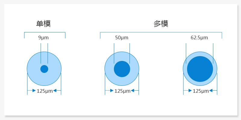
Multimode fibre is a fibre whose core is wide enough to support several spatial modes at the same time. Unlike single-mode fibre, which carries the fundamental mode only, a multimode core is much larger (typically 50 μm, 62.5 μm or more) and the numerical aperture is usually larger as well, so light entering at different angles travels along different mode paths. Its main advantage is easy coupling: it does not demand a high beam quality from the source, it tolerates misalignment and it costs less. The price is intermodal dispersion, which limits the bandwidth and the distance, which is why multimode fibre is used mainly for short-range links.

2. Working principle: how is multimode fibre achieved?

Several modes can be transmitted at the same time in a multimode fibre, and the mode count is set by the V parameter. For a step-index fibre the total number of modes M is approximately V²/2. The larger the V parameter, the more modes are supported.
For example: in a 50/125 μm multimode fibre with NA = 0.20 at a working wavelength of 850 nm, V = 2π × 25 × 0.20 / 0.85 ≈ 37, which gives about 37²/2 ≈ 685 modes.
Step-index multimode fibre
In a step-index multimode fibre the path lengths of the different modes differ greatly — the fundamental mode travelling along the axis takes the shortest path, while the higher-order modes reflected at steep angles take the longest. The light of the different modes therefore reaches the output at different times, that is intermodal dispersion, which broadens the optical pulse and limits the bit rate and the distance.
Graded-index multimode fibre
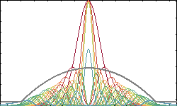
By shaping the core refractive index so that it decreases gradually from the centre outwards following a parabolic profile, the intermodal dispersion is largely cancelled. In the outer region, where the index is lower, the light travels faster, and that exactly compensates the extra time the higher-order modes need along their longer paths. An optimised graded-index multimode fibre such as OM3 or OM4 offers a mode bandwidth more than an order of magnitude above the step-index type. The mode count of a multimode fibre follows the V number; when V is large the total is approximately V²/2 (counting both polarisation directions). A multimode fibre with a 50 μm core and NA = 0.2 at 850 nm has V ≈ 37 and supports about 680 modes.
3. Key parameters: reading the specifications of multimode fibre
Intermodal dispersion and the bandwidth-length product
Intermodal dispersion is the main source of dispersion in multimode fibre: the modes enter at different angles, follow different paths over the same length of fibre and arrive at different times, so the optical pulse broadens.
The intermodal dispersion of a step-index fibre is the worst, because the axial propagation speeds of the modes differ substantially. For a step-index multimode fibre the delay difference between the highest-order mode and the fundamental mode is about:
Δτ ≈ (n₁·L·NA²) / (2·n₂·c)
A graded-index (GI) fibre lowers the core refractive index gradually from the centre outwards following a parabolic profile, so that the rays of the different modes travel at nearly the same axial speed (higher-order modes follow a longer path but move faster in the lower-index region). This cuts the intermodal dispersion dramatically; the bandwidth of a graded-index fibre can be about two orders of magnitude above that of a step-index fibre.
💡 Bandwidth-length product
The transmission capability of multimode fibre is usually quoted as “bandwidth × distance”, in MHz·km or GHz·km. It is a product, so the further you go the less bandwidth is left: about 500 MHz·km for OM2, 2000 MHz·km for OM3 and 4700 MHz·km for OM4.
Note that a graded-index fibre does not remove the intermodal dispersion completely, it only reduces it by a large factor. Material dispersion and waveguide dispersion (chromatic dispersion) are still present, and the higher-order modes remain sensitive to microbending.
Core formulas
Estimating the mode count: in a step-index multimode fibre the total number of guided modes is about:
N ≈ V² / 2
For example: for a 50/125 μm fibre with NA = 0.2 at 850 nm, V ≈ 36.9 and the mode count is about 680.
Graded-index profile: the core refractive index of a graded-index (GI) fibre follows an α profile:
n(r) = n₁ √[1 – 2Δ(r/a)^α]
At α = 2 the profile is parabolic, and this is where the intermodal dispersion is smallest and the bandwidth largest. The optimum α is around 2 + ε (just above 2), with material-dispersion compensation taken into account.
Bandwidth advantage of graded-index fibre: the parabolic profile makes the rays of the different modes self-focus, so that the axial ray (short path, high n, slow) and the oblique rays (long path, low n at the edge, fast) travel for almost the same time; the intermodal dispersion can be one to two orders of magnitude lower than in a step-index fibre.
Reading the key parameters is the starting point for assessing the performance of multimode fibre. The table below sets out the main specifications and what they mean:
| Parameter | Meaning | Engineering significance |
|---|---|---|
| Core diameter | Common sizes are 50 μm, 62.5 μm, 100 μm, 200 μm, 400 μm and 600 μm | Sets the number of modes that can be supported and how easy the fibre is to couple; 50 μm and 62.5 μm are the common choices |
| Cladding diameter | Usually 125 μm for a small core, or larger for large-core power fibre | A standard cladding diameter lets the fibre use existing connectors and fusion splicers, which avoids the cost of re-qualifying the system whenever the equipment is changed. |
| Numerical aperture (NA) | The NA of multimode fibre is typically 0.2-0.37; a higher NA means a larger acceptance angle | Sets the light acceptance; multimode fibre is usually 0.20-0.275, with a wide coupling tolerance |
| Number of modes | Set by the V number, V = (2πa/λ) × NA | Set by the V number, it affects the bandwidth and the coupling efficiency, and is about V²/2 |
| Intermodal bandwidth | The bandwidth per unit length allowed by the modal dispersion, usually in MHz·km or GHz·km | It sets how fast the Ethernet link can run over the fibre; a 100 m link at 10 Gbit/s needs OM3 or better. |
| Transmission loss | The loss of multimode fibre is typically higher than in single-mode fibre: about 2-3 dB/km at 850 nm and about 0.5-1 dB/km at 1300 nm | 850 nm and 1300 nm are the two working windows of multimode fibre |
| Differential mode delay (DMD) | Measures the group-delay difference between the modes; the smaller the DMD, the higher the bandwidth | The smaller the DMD, the less the pulse broadens, which makes it the main figure used to decide whether a multimode fibre can be upgraded to a faster link. |
4. Main types: what kinds of multimode fibre are there?
ISO/IEC 11801 multimode fibre grades
| Grade | Core/cladding | Effective modal bandwidth at 850 nm | Typical application |
|---|---|---|---|
| OM1 | 62.5/125μm | 200 MHz·km | Fast Ethernet, legacy building cabling |
| OM2 | 50/125μm | 500 MHz·km | Gigabit Ethernet, short-to-medium data links |
| OM3 | 50/125 μm (laser-optimised) | 2000 MHz·km | 10 Gigabit Ethernet, data centre backbone (300 m) |
| OM4 | 50/125 μm (laser-optimised) | 4700 MHz·km | 10/40/100 Gigabit Ethernet, data centres (550 m) |
| OM5 | 50/125 μm (wideband multimode) | 4700 MHz·km (850 nm) | SWDM short-wavelength division multiplexing, high-speed data centre interconnect |
OM3, OM4 and OM5 are all laser-optimised multimode fibres (LOMMF); they are optimised for the narrow linewidth of VCSEL sources by tightening the differential mode delay (DMD).
Multimode fibre can be classified in many ways, and each dimension helps you understand its characteristics from a different angle. The most common ones are introduced below:
By refractive-index profile
Step-index multimode fibre
A uniform core refractive index; cheap, but with large intermodal dispersion, so it is now rarely used for data communications
Graded-index multimode fibre
A parabolic refractive-index profile that greatly reduces the intermodal dispersion; this is the mainstream type for data communications
By ISO/IEC grade (performance class)
OM1
62.5 μm core, optimised for LED sources, low bandwidth (200 MHz·km @ 850 nm)
OM2
50 μm core, slightly better than OM1 (500 MHz·km @ 850 nm)
OM3
50 μm core, laser-optimised graded-index fibre supporting 10 Gbit/s over 300 m (2000 MHz·km @ 850 nm)
OM4
50 μm core, the upgraded OM3 with a higher bandwidth (4700 MHz·km @ 850 nm) and a longer reach
OM5
Wideband multimode fibre, optimised for short-wavelength division multiplexing (SWDM)
By application
Multimode fibre for telecommunications
50/62.5 μm cores, used in local networks and data centres
Large-core power delivery fibre
Cores of 100-600 μm or even larger, used for laser power delivery, medical lasers and industrial processing
Plastic optical fibre (POF)
A polymer core, extremely cheap, used in automotive, domestic and short-range industrial links
5. Applications: where is multimode fibre used?
The applications of multimode fibre span several fields; the main directions are:
- Data centres and local networks: because multimode fibre is easy to couple and the optical devices that go with it are cheap, it is widely used for short, high-speed links inside data centres and buildings. OM3 and OM4 support 10G, 40G and even 100G Ethernet
- Laser power delivery: large-core multimode fibre is used to carry high-power laser light, for example in industrial laser processing (cutting, welding, marking) and in the energy delivery of medical laser surgery
- Fibre illumination: multimode fibre delivers the illumination light efficiently, for decorative lighting and for medical endoscope illumination
- Pump light delivery: in a double-clad fibre laser, multimode fibre carries the pump light from the semiconductor laser to the gain fibre
- Imaging fibre bundles: bundles made of tens of thousands of multimode fibres can transmit images, as used in industrial and medical endoscopes
- Fibre sensing: some distributed and low-accuracy sensing schemes use multimode fibre to keep the cost down
👉 Want to see more real application cases? Visit the application case page of Soar Laser, or contact our technical team directly for professional advice.
6. Common misconceptions
Misconception 1: a large core means higher power handling
A larger core is only one factor in the power handling. The power a fibre can carry also depends on the numerical aperture, the coating material (acrylate vs polyimide), the cladding diameter and the end-face quality. Two 105 μm-core fibres, for example, differ in power handling and beam quality between a low NA (0.15) and a high NA (0.22). Large-core power delivery fibre also usually uses a pure silica cladding and a special coating, and is a completely different product from a telecommunications multimode fibre.
Misconception 2: graded index removes the intermodal dispersion completely
A graded-index (GI) fibre greatly reduces the intermodal dispersion through its parabolic refractive-index profile, but it does not remove it. The reasons include: the real profile deviates from the ideal parabola (the α value must be tightly controlled), material dispersion varies with the mode, and the higher-order modes leak away. Laser-optimised fibres such as OM3 and OM4 improve the bandwidth further by controlling the differential mode delay (DMD) tightly, but they still remain orders of magnitude below single-mode fibre in bandwidth.
Misconception 3: all 50 μm multimode fibres perform about the same
Even with the same core diameter, the performance of different grades differs hugely. OM1 is 62.5/125 μm, while OM2, OM3, OM4 and OM5 are all 50/125 μm — yet the bandwidth gap runs to tens of times: OM2 offers only 500 MHz·km @ 850 nm, OM3 reaches 2000 MHz·km and OM4 goes as high as 4700 MHz·km. These differences come from the precision of the refractive-index profile, the purity of the material and the level of DMD control, not from the core diameter.
Misconception 4: multimode fibre is only good for low-speed links
Intermodal dispersion does limit long-distance high-speed transmission over multimode fibre, but for short links multimode fibre still has the edge. With parallel optics (100GBASE-SR4 uses four 25G lanes) and short-wavelength division multiplexing (SWDM, supported by OM5), multimode fibre can carry 100G and even 400G inside a data centre, and the matching optical modules cost far less than the single-mode solution.
7. Recommended reading
- What is an optical fibre? How light travels thousands of kilometres in a glass thread
- What is single-mode fibre? Why communication networks use it
- What is a fused fibre coupler? How two fibres split light
- What is a laser mode? What do transverse and longitudinal modes mean?
- Fibre coupling technology and coupling efficiency
Leave a Reply