


What Is an Optical Fibre? How Light Travels Thousands of Kilometres in a Glass Thread
An optical fibre confines light in a glass core by total internal reflection, and every property of the fibre is set by the core diameter, the refractive index difference between core and cladding, and the numerical aperture. The following sections cover the guiding mechanism, the key parameters, the main types and the engineering applications.
Table of contents
- 1. What is an optical fibre? Getting the core concept straight
- 2. Working principle: how an optical fibre works
- 3. Key parameters: reading the specifications of an optical fibre
- 4. Main types: what kinds of optical fibre are there
- 5. Applications: where are optical fibres used
- 6. Common misconceptions: pitfalls to avoid
1. Core concept: what is an optical fibre?
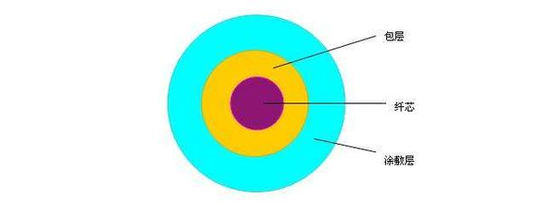
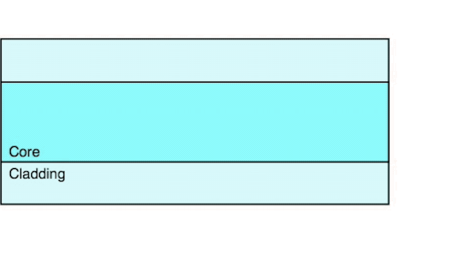
An optical fibre is a long, thin, flexible optical waveguide, usually made of glass (mainly fused silica, i.e. silicon dioxide), that confines the light in the core so that it propagates by total internal reflection over distances of hundreds of kilometres. Optical fibres are core components in photonics and the cornerstone of modern communication infrastructure. The most basic structure consists of a central core with the higher refractive index surrounded by a cladding with the lower refractive index, which confines the light in the core by total internal reflection. The outer diameter of a fibre is usually only 125 μm (cladding diameter), comparable to a human hair (typically 50–100 μm), yet after a polymer coating is applied it gains considerable flexibility and mechanical strength.
2. Working principle: how does an optical fibre work?
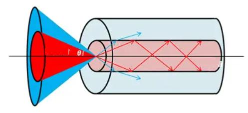
The numerical aperture (Numerical Aperture, NA) is one of the most central parameters of a fibre, describing its ability to collect incident light. It is determined solely by the refractive index difference between core and cladding and is independent of the fibre geometry. A larger NA means a larger acceptance angle and easier coupling, but also more supported modes.
💡 What the numerical aperture means physically
The NA fixes the sine of the maximum angle θ_max between an incident ray and the fibre axis that the fibre can accept, i.e. NA = sinθ_max. A typical single-mode fibre has an NA of about 0.10–0.14, and a multimode fibre about 0.20–0.29.

The V parameter (normalised frequency) is another dimensionless quantity that combines three factors — wavelength, core size and refractive index difference — and it determines how many modes the fibre can support.
The core physical mechanism of light guiding in a fibre is total internal reflection. When light travels from the higher-index core to the core-cladding interface at an angle greater than the critical angle, the ray is totally reflected back into the core and travels along the axis. That said, this is a simplified geometric-optics picture; strictly speaking wave optics is needed: light propagates in discrete “modes”, each corresponding to a stable transverse electric-field distribution.
The numerical aperture (NA) of a fibre describes how much light it can collect and is set by the index difference between core and cladding: the larger the NA, the wider the range of incident angles accepted and the easier the coupling. The number of modes a fibre supports is determined by the normalised frequency V number, which depends on the core radius, the numerical aperture and the wavelength. When V is below 2.405 the fibre supports only the fundamental mode (LP₀₁) and is therefore single-mode; for larger V it supports several modes and is therefore multimode.
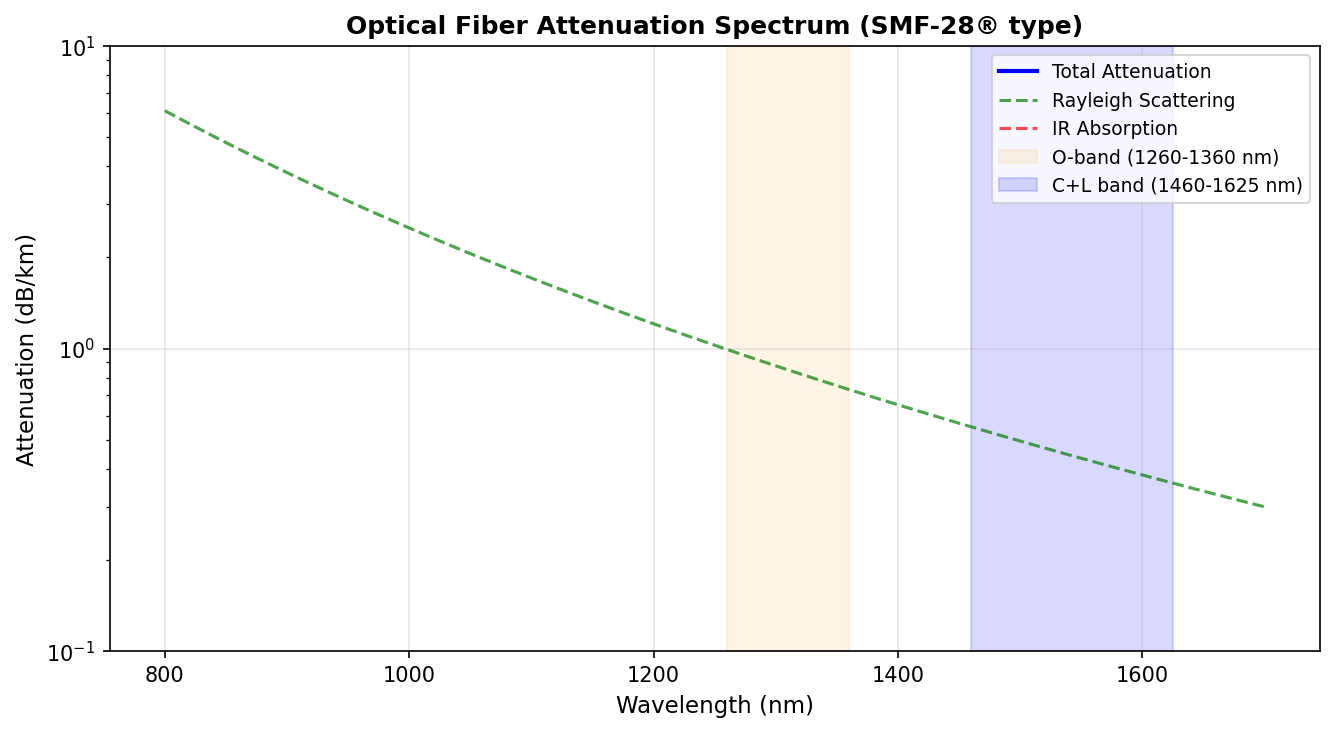
Light loses power as it travels in a fibre, from three main mechanisms: Rayleigh scattering (caused by microscopic density fluctuations in the glass, inversely proportional to the fourth power of the wavelength), OH⁻ ion absorption (with an absorption peak near 1380 nm) and multiphonon absorption at long wavelengths. A silica fibre has its lowest attenuation near 1550 nm, where it can fall below 0.2 dB/km.
3. Key parameters: reading the specifications of an optical fibre

The three main sources of fibre loss
The transmission loss of an optical fibre comes from three directions:
① Absorption loss: this includes ultraviolet absorption (electronic transitions, significant at short wavelengths), infrared absorption (multiphonon absorption, significant at long wavelengths) and OH⁻ ion absorption (the water peak near 1380 nm). The intrinsic absorption of a silica fibre is lowest near 1.55 μm, at about 0.2 dB/km.
② Scattering loss: mainly Rayleigh scattering, caused by microscopic refractive index inhomogeneities in the core, with the loss inversely proportional to the fourth power of the wavelength (α ∝ 1/λ⁴). This is the main reason why short wavelengths (850 nm) suffer higher loss.
③ Bending loss: this includes macrobending loss (bending radii far larger than the fibre diameter) and microbending loss (small deformations on the fibre surface). The smaller the bend radius and the longer the wavelength, the larger the bending loss.
💡 The three low-loss windows of an optical fibre
The 850 nm window: used by first-generation optical communication, with about 2.5 dB/km of loss, mainly for short-reach multimode systems; the 1310 nm window: about 0.4 dB/km of loss, close to the zero-dispersion wavelength; the 1550 nm window: the lowest loss, about 0.2 dB/km, and the main band for long-haul single-mode optical communication.
Knowledge extension: the loss windows of an optical fibre
The loss spectrum of a silica fibre shows several low-loss windows:
- The 850 nm window: the wavelength of first-generation optical communication, about 2.5 dB/km of loss, mostly used for short-reach multimode data links
- The 1310 nm window: close to the zero-dispersion wavelength, about 0.4 dB/km of loss, the main band of traditional telecom networks
- The 1550 nm window: the lowest-loss window, as low as 0.2 dB/km, the working band for long-haul high-speed links and for EDFAs
- The 1380 nm absorption peak: caused by OH⁻ ions; low-water-peak fibres (such as Corning SMF-28e) have largely removed this peak
The loss comes mainly from Rayleigh scattering (proportional to λ⁻⁴, dominant on the short-wavelength side), infrared absorption (material multiphonon absorption, dominant on the long-wavelength side) and OH⁻ absorption (peaks at specific wavelengths).
Core formulas
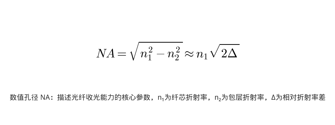
Numerical aperture (NA): the parameter that describes how much light a fibre collects, set by the index difference between core and cladding:
NA = √(n₁² – n₂²) ≈ n₁√(2Δ)
where n₁ is the core refractive index, n₂ is the cladding refractive index, and Δ = (n₁-n₂)/n₁ is the relative index difference. The larger the NA, the wider the acceptance angle and the easier the coupling.
Normalised frequency (V number): determines how many modes the fibre supports:
V = (2πa/λ) × NA
where a is the core radius and λ the operating wavelength. When V < 2.405 the fibre supports only the fundamental mode (single-mode); for larger V it supports several modes. The total mode count of a multimode fibre is about V²/2.
Understanding the core parameters is the basis for evaluating fibre performance. The table below sets out the key specifications and what they mean:
| Parameter | Meaning | Engineering significance |
|---|---|---|
| Core diameter | The diameter of the central region in which the light is confined; a few micrometres for single-mode fibre, up to 50–600 μm for multimode fibre | It determines how many modes the fibre supports and how easy it is to couple into |
| Cladding diameter | Standard silica fibre is usually 125 μm | Standard silica fibre is usually 125 μm, which sets the mechanical strength and compatibility |
| Numerical aperture (NA) | The parameter measuring the light-collecting ability of the fibre, reflecting the index difference between core and cladding | It sets the acceptance angle tolerance and the choice of light source |
| V number (normalised frequency) | The dimensionless parameter that determines how many modes the fibre supports | It determines the number of supported modes and whether the fibre works in single-mode or multimode operation |
| Transmission loss | The attenuation of optical power per unit length, in dB/km; high-quality single-mode fibre can go as low as 0.2 dB/km at 1550 nm | It sets the maximum distance without regeneration and the power budget of the system |
| Mode field diameter (MFD) | The effective width of the transverse field distribution in a single-mode fibre, usually slightly larger than the core diameter | It affects splicing loss and coupling efficiency |
| Cut-off wavelength | The wavelength threshold below which a single-mode fibre begins to support higher-order modes and becomes multimode | The threshold at which a single-mode fibre starts to support higher-order modes; below it the fibre becomes multimode |
| Dispersion | The broadening of an optical pulse during transmission, including material dispersion, waveguide dispersion and modal dispersion | It limits the transmission distance and the data rate of high-speed links |
4. Main types: what kinds of optical fibre are there?
Optical fibres can be classified in many ways, and each dimension reveals different aspects of their behaviour. The common ones are introduced below:
By number of supported modes
Relationship between the V parameter and the mode count: for a step-index multimode fibre the total number of modes is approximately V²/2. When V < 2.405 only the fundamental mode (LP₀₁) exists in the fibre, i.e. single-mode transmission.

For a detailed comparison of single-mode and multimode fibre, see the dedicated articles on single-mode fibre and multimode fibre.
Single-mode fibre
Fine core (~8–10 μm), supporting only the fundamental mode, with good beam quality; used for long-haul high-speed communication and high-power fibre lasers
Multimode fibre
Large core (50 μm, 62.5 μm or more), supporting several modes, easy to couple but with large modal dispersion; suited to short-reach links and optical power delivery
By refractive index profile
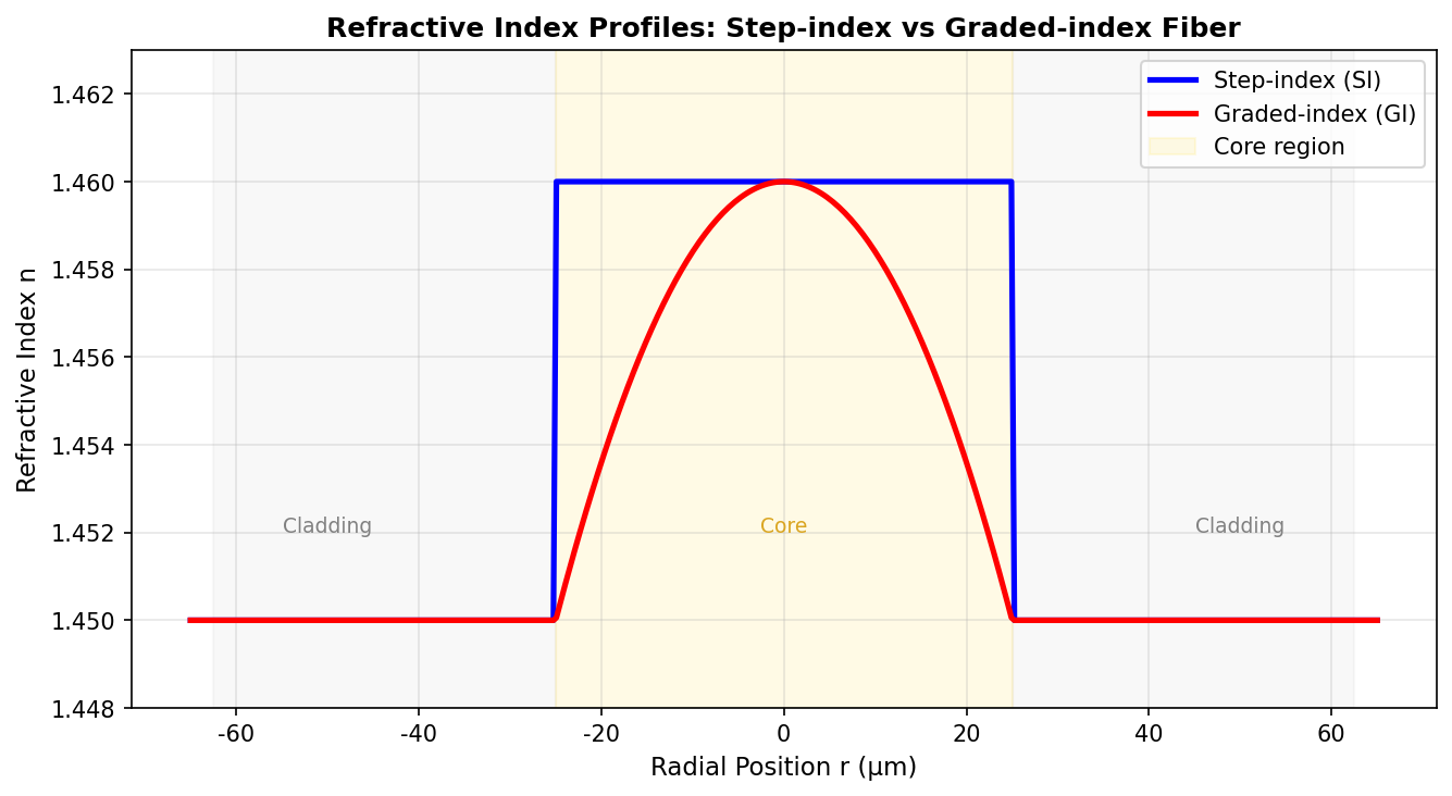
Step-index fibre
The core index is uniform and drops abruptly at the cladding
Graded-index fibre
The core index falls gradually from the centre outwards (usually with a parabolic profile), which markedly reduces modal dispersion
By function
Passive fibre
Transmits light only and produces no gain
Active fibre
The core is doped with rare-earth ions (such as erbium, ytterbium or thulium) and can serve as a laser gain medium
By material
Silica fibre
The most common type, with low loss and high strength
Fluoride fibre
Good mid-infrared transmission and low phonon energy
Chalcogenide glass fibre
For far-infrared and nonlinear applications
Plastic optical fibre (POF)
Low cost and highly flexible, used for short-distance transmission
Special fibres
Including polarisation-maintaining fibre, photonic crystal fibre, double-clad fibre, large-mode-area fibre and hollow-core fibre, each with its own distinctive properties and use cases.
5. Applications: where are optical fibres used?
Fibre applications cover several fields. The main directions are:
- Optical communication: this is by far the largest application. Single-mode fibre forms the backbone of the global internet; one fibre can carry terabits of data and is immune to electromagnetic interference.
- Fibre lasers and amplifiers: rare-earth-doped active fibre is the gain medium of fibre lasers, offering high beam quality, good thermal performance and a compact structure; it is widely used in industrial processing, medicine and research.
- Fibre sensing: exploiting the sensitivity of fibre to temperature, strain and pressure, distributed or point measurements are realised, widely used for structural monitoring of buildings, oil pipelines, aerospace and aviation.
- Optical power delivery: laser energy is carried by fibre to a defined location, for example in laser marking, welding or surgical energy delivery.
- Illumination and imaging: fibre bundles are used in medical and industrial endoscopes.
- Spectroscopy and nonlinear optics: special fibres such as photonic crystal fibre are used for supercontinuum generation and frequency conversion.
👉 Want to see more real application cases? Visit the application case page of Soar Laser, or contact our technical team directly for professional advice.
6. Common misconceptions
Misconception 1: the thicker the fibre, the greater its transmission capacity
The transmission capacity depends on the type of fibre and the operating wavelength, not on its thickness. A single-mode fibre has a core of only 8–10 μm yet can carry terabit-class data over hundreds of kilometres; large-core multimode fibre is easy to couple but suffers large modal dispersion, so its bandwidth and distance are actually limited. In addition, the upper limit on transmitted power is set mainly by the cladding diameter, the coating material and the end-face quality, and is not simply proportional to the core size.
Misconception 2: optical fibre can only carry visible light
The main operating band of silica fibre is the near infrared (800–1600 nm), not the visible. Fibres made of other materials cover a wider spectrum: fluoride fibre extends to the 5 μm mid-infrared, chalcogenide fibre reaches beyond 10 μm, and photonic crystal fibre can even work in the deep ultraviolet. The transmission windows of a fibre are set by the intrinsic absorption and scattering properties of the material.
Misconception 3: total internal reflection means the light loses no energy at all
Total internal reflection is only an approximation from geometric optics. In reality part of the optical field penetrates into the cladding as an evanescent wave, and this is the physical basis of evanescent-wave coupling between two fibres whose cores are close together. Rayleigh scattering, material absorption and bending loss all attenuate the optical power as well; high-quality single-mode fibre has a loss of about 0.2 dB/km in the 1550 nm window.
Misconception 4: plastic optical fibre is always low performance
Although plastic optical fibre (POF) has higher loss than silica, it has advantages of its own: a large core (typically 1 mm) makes coupling and connectorisation extremely easy, it is more flexible, it resists vibration and impact well, and it costs very little. In short-reach scenarios such as in-vehicle networks, home wiring and industrial control, POF is a very cost-effective choice. New polymer materials keep pushing the performance envelope of POF.
7. Recommended reading
- What is single-mode fibre? Why communication uses it
- What is multimode fibre? What it is like to run many beams at once
- What is polarisation-maintaining fibre? How to stop the polarisation drifting
- What is active fibre? The magical fibre that amplifies light
- What is a fibre laser? Why it dominates the industrial laser market
- What is an optical spectrum analyser? How the colour content of a laser is analysed
8. References
- RP Photonics Encyclopedia – Optical Fibers
- Corning – Optical Fiber Fundamentals
- The Fiber Optic Association (FOA) – Total Internal Reflection
- Hecht, J. – Understanding Fiber Optics, 5th Edition
Leave a Reply