


1. Core concept: what is an optical power meter?
An optical power meter is the instrument most used in laser laboratories: it converts the output current of a photodetector into incident optical power through a calibration coefficient, and its range extends from microwatts all the way to kilowatts.
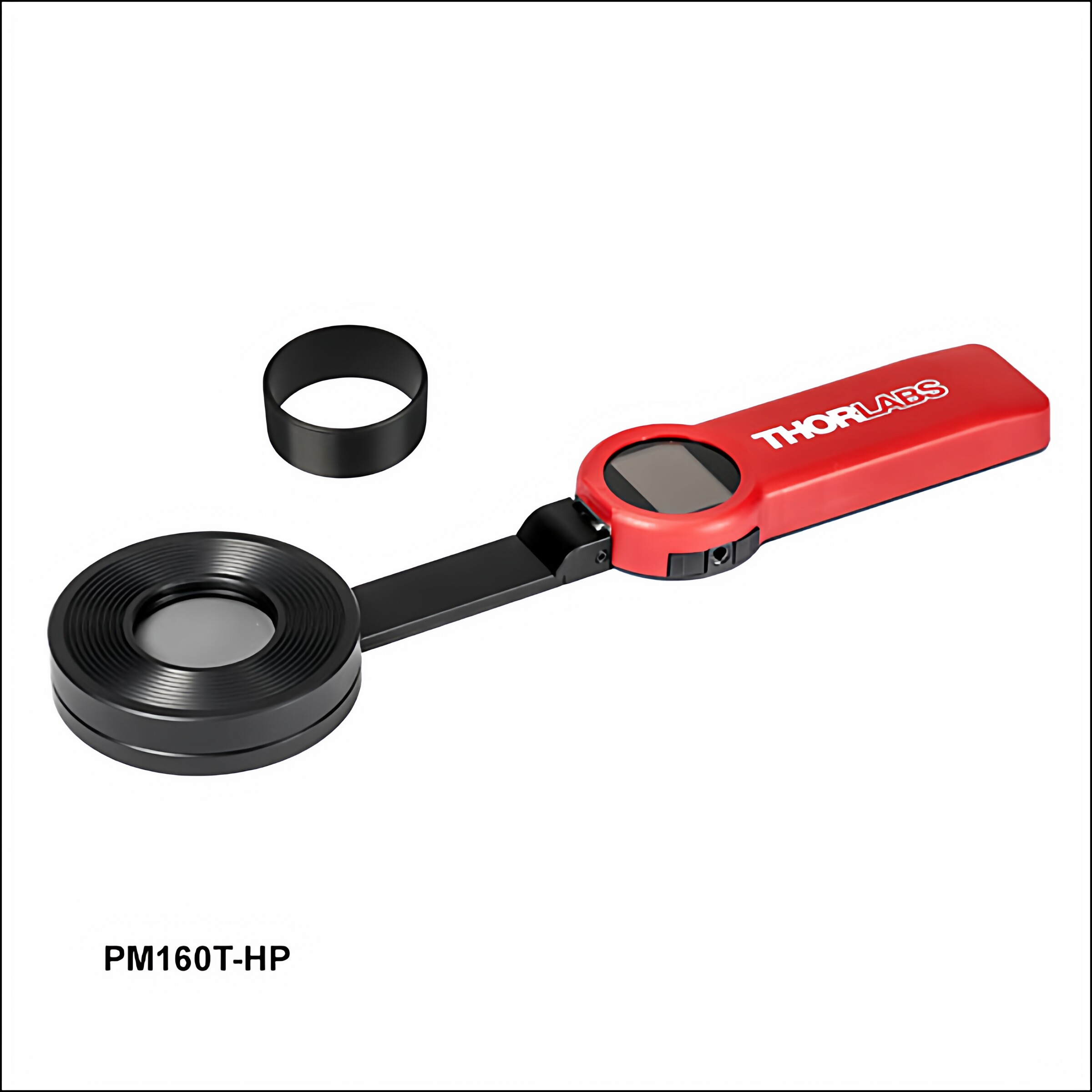
An optical power meter is an instrument for measuring the optical power of a laser or other beam (usually in watts, milliwatts or microwatts, and often expressed in dBm). It is like the “electronic scale” of an optics laboratory — whenever you need to know how much energy a laser beam delivers, the power meter is the most direct tool.
An optical power meter consists of two parts: the sensor head (sensor head), which converts the optical signal into an electrical signal; and the display unit (display unit), which processes the signal and shows the reading. Depending on the sensor principle, power meters cover an extremely wide range from nanowatts to kilowatts, and they are indispensable in laser R&D, production and quality control.
It is reasonable to ask why accurate power measurement is needed. Almost every laser application depends on power: a cut that is too shallow may mean insufficient power, a weld that does not hold may mean unstable power, and a treatment that disappoints may mean an inaccurate dose. Understanding the principle, the parameters and the selection method of power meters is the first step toward using a laser well.
2. Working principle: how does an optical power meter work?
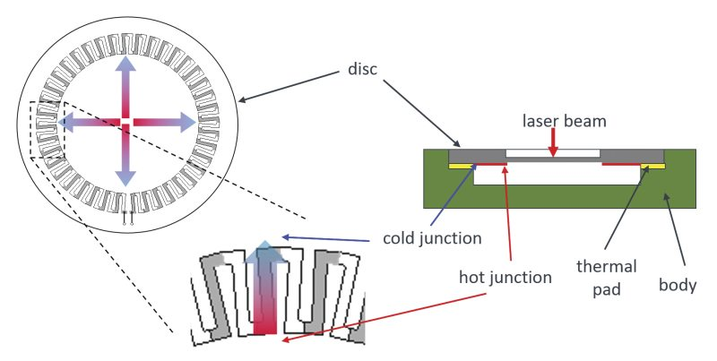
The core of an optical power meter is the conversion of optical energy into a measurable electrical signal, and there are two main types of principle:
Thermopile power meters (thermopile power meter)
This is the classic and most widely used type of power meter, and it works on the principle of photothermal conversion:
1. Optical absorption and heating: the incident laser strikes the absorbing layer of the sensor head (usually a black coating such as a black-body absorber), and the optical energy is fully absorbed and converted into heat, raising the temperature of the absorber.
2. Temperature-difference measurement: a temperature difference forms between the absorber and the base of the probe (the heat sink), and this difference is measured by a thermopile (thermopile, consisting of several thermocouples connected in series). The output voltage of the thermocouple is proportional to the temperature difference, and the temperature difference is in turn proportional to the incident optical power.
3. Signal processing and display: the small voltage signal from the thermopile is amplified and calibrated, then displayed on the instrument as optical power.
The great advantage of a thermopile power meter is its flat spectral response — almost independent of wavelength, because as long as the light is absorbed, every wavelength produces the same amount of heat. That means it needs no frequent wavelength calibration over a very broad wavelength range.
Photodiode power meters (photodiode power meter)
This type uses a photodiode as the sensing element:
1. Photovoltaic conversion: incident photons are absorbed in the depletion region of the photodiode, generating electron-hole pairs that produce a photocurrent proportional to the incident optical power in the external circuit.
2. Current-to-voltage conversion and amplification: the photocurrent is converted into a voltage by a precision transimpedance amplifier and then amplified and calibrated.
3. Wavelength correction: since the responsivity of a photodiode varies strongly with wavelength, the wavelength of the laser under test must be entered, and the instrument applies wavelength compensation based on the stored calibration curve to obtain an accurate power reading.
The advantages of a photodiode power meter are its high sensitivity and fast response: it can measure optical powers down to the nanowatt or even picowatt level, which a thermopile cannot. Its spectral response is not flat, however, and its upper power limit is lower (high power requires an external attenuator).
Integrating sphere probes (integrating sphere)
An integrating sphere is a special light-collection accessory whose inner wall is coated with a highly reflective diffusing material. Light entering the sphere is made uniform by multiple diffuse reflections, and the detector is mounted in a small port in the sphere wall for the measurement.
Situations where an integrating sphere probe is appropriate:
- Off-axis beams: where the beam does not enter strictly along the optical axis, the integrating sphere removes the angular dependence
- Widely diverging beams: sources with a large divergence, such as LED output or multimode fibre output, may not be collected completely by an ordinary probe
- Fibre output measurements: light emerging from a fibre end face diverges strongly, and an integrating sphere collects it efficiently
- Measurements with tight uniformity requirements: where the result must be insensitive to the spatial distribution of the beam
Thermopile vs photodiode probe: a selection comparison
| Comparison item | Thermopile probe | Photodiode probe |
|---|---|---|
| Working principle | Photothermal conversion (absorption → heating → thermopile voltage) | Photovoltaic effect (photon → electron-hole pair → photocurrent) |
| Spectral response | Extremely broad and flat (e.g. 0.19–25 μm), almost independent of wavelength | Set by the material; silicon detectors cover roughly 200–1100 nm (190 nm for UV-enhanced types), and responsivity varies strongly with wavelength |
| Power range | Wide (mW to kW), suitable for medium and high power | Lower (nW/μW to mW/W, extendable with attenuators), suitable for low power |
| Sensitivity | Lower (μW to mW) | High (nW down to pW) |
| Response speed | Slow (0.2 s to several seconds, slower at high power) | Fast (microseconds to milliseconds) |
| Wavelength setting | Not required in the visible to near infrared, but high-accuracy measurement still calls for wavelength correction | The wavelength must be entered (compensated by a calibration curve) |
| Typical applications | Medium and high power measurement, industrial lasers, multi-wavelength sources | Low power measurement, fast pulses, optical communications |
3. Key parameters: reading the performance specifications of an optical power meter
Knowing the concept and the principle is not enough to evaluate an optical power meter; you also need to understand its key parameters. The table below sorts out the core parameters.
| Parameter | Meaning | Why it matters |
|---|---|---|
| Power measurement range | The upper and lower power limits that the instrument can measure accurately. Thermopile types usually start at the mW level and go up to kW; photodiode types run from nW/μW up to mW/W and can be extended with attenuators. | The power limits within which measurements are accurate, set by the sensor type. The selected range must cover the power under test: if the signal is too weak it falls below the noise floor and reads inaccurately, and if it is too strong the head can be damaged. |
| Spectral response range | The wavelength range over which measurements are accurate. The range of a thermopile is very broad (from the ultraviolet to the far infrared, e.g. 0.19–25 μm), while a photodiode type depends on the material (silicon detectors cover roughly 200–1100 nm and UV-enhanced types extend to 190 nm, InGaAs covers about 800–1700 nm). | It is set by the sensor material, and the responsivity differs from wavelength to wavelength. The instrument must be calibrated at the wavelength being measured, or the error will be large. The ultraviolet end of silicon detectors deserves attention: ordinary silicon types start at 200 nm, and 190 nm requires an UV-enhanced detector with a quartz window. |
| Measurement accuracy | Typical accuracy is ±3 % to ±5 % (near full scale). Accuracy depends on many factors, including calibration quality, the uniformity of the detector response and temperature drift. Applications that demand high accuracy normally require periodic calibration traceable to national measurement standards (such as NIST or PTB). | The deviation between the measured value and the true power, usually expressed as a percentage. High-accuracy power meters are used for value transfer and for calibrating products before they leave the factory. |
| Response speed | The time needed for the reading to settle. Thermopile types are slow (0.2 s to several seconds, slower in high-power models), while photodiode types respond quickly. | The settling time of the reading, determined by the sensor type. Pyroelectric and thermocouple types are slow (seconds), while photodiode types are fast (microseconds). |
| Effective photosensitive area | The size of the effective light-receiving area of the sensor, typically from a few millimetres to a few centimetres. When selecting, make sure the laser spot falls entirely within it. | The size of the effective detection area. The beam must enter the effective region completely, or the reading will be too low. Large-aperture heads suit beams with large divergence. |
| Damage threshold / maximum intensity | The maximum intensity (W/cm²) the sensor can withstand without damage. Note that this is not total power but power per unit area — the smaller the spot, the easier the sensor is damaged. | The maximum power density (W/cm²) the sensor survives without damage. Power density is the more critical limit: a small spot can exceed the damage threshold even when the total power is modest. |
| Interface and communication | Whether USB, GPIB, RS-232 and other digital interfaces are supported, and whether an analogue output is provided for integration into automated measurement systems. | The type of data output and control interface, such as USB, GPIB or RS-232. It determines how easily the meter integrates with other equipment and how far automation can go. |
4. Main types: what kinds of optical power meters are there?
Optical power meters can be classified in many ways, and each dimension reveals different aspects of their behaviour. The common ones are introduced below:
By sensor principle
#### Thermopile types (thermopile)
The most general-purpose type, with a wide spectral range and a large power range, suited to medium and high power measurements.
#### Photodiode types (photodiode)
High sensitivity and fast response, suited to low-power and fast measurement applications.
#### Pyroelectric types (pyroelectric)
Used mainly for pulse energy measurement (energy meters), and also for average power measurement of pulsed output.
By power range
#### Low-power types (low power)
From nW to mW, usually based on photodiodes and used for weak-light detection.
#### Medium-power types (medium power)
From mW to W, the most common range, available in both thermopile and photodiode types.
#### High-power types (high power)
From a few watts to kilowatts, based on thermopiles and requiring fan or water cooling.
By input configuration
#### Free-space types (free space)
The beam strikes the sensor head directly; the most common arrangement in the laboratory.
#### Fibre-coupled types (fibre-coupled)
Input through a fibre connector, used mainly in optical communications and often displaying dBm.
#### Integrating sphere types (integrating sphere)
The head includes an integrating sphere, so it accepts beams with large divergence (such as LED or fibre output) and gives good spatial uniformity.
By display arrangement
#### Benchtop types (benchtop)
With a separate display unit and full functionality, intended for laboratory use.
#### USB types (no display unit)
Only the sensor head is provided; it connects to a computer over USB and is controlled and read in software, which keeps it portable and inexpensive.
#### Handheld types (handheld)
Battery powered and compact, convenient for field use and for carrying around.
Each type of optical power meter has its own advantages and drawbacks; there is no absolute “best,” only the “most suitable.” The choice should follow the specific application — the power range, the wavelength range, the required speed, the budget and other practical constraints.
5. Applications: where are optical power meters used?
The optical power meter is the most fundamental measurement tool of the laser and optoelectronics industries, and its applications are extremely broad:
- Factory test and calibration of lasers: almost every laser product has its output power calibrated with a power meter before shipment, since this is the most basic quality specification.
- Laboratory R&D testing: the everyday measurement of the output power of all kinds of lasers in an optics laboratory; it is one of the most frequently used tools for setting up optical paths and debugging systems.
- Laser processing monitoring: in laser cutting, marking and welding equipment, the laser power is measured periodically so that processing quality stays consistent.
- Optical communication testing: measuring the optical power level in a fibre link to judge signal attenuation and the health of the system. The power meter is the most commonly used tool in communication room maintenance.
- Transmittance and reflectance measurement of optical components: together with a source, measuring the transmitted or reflected power of lenses, filters and other elements to calculate losses.
- Calibration of medical laser equipment: medical lasers (ophthalmic and dermatological lasers, for example) must have their power calibrated regularly so that the delivered dose is accurate.
- Production testing in optical communications: power testing on optical module and device production lines to decide whether a product passes.
- Environmental and safety testing: measuring the leakage power of laser equipment to confirm compliance with safety standards.
6. Common misconceptions
Many beliefs about optical power meters are plausible but wrong. Check whether any of the following misconceptions apply to you:
Misconception 1: the value a power meter reads is absolutely accurate
A power meter has a certain measurement uncertainty, typically at the level of ±3 % to ±5 %, and its accuracy drifts with time in use, temperature and the wavelength setting. High-accuracy measurement requires a reference power meter calibrated by an accredited metrology institute, used within the validity period of that calibration. In addition, accuracy degrades markedly when the reading approaches the bottom of the range, so it is best to select a range where the measured value sits near two thirds of full scale.
Misconception 2: as long as the total power stays within range, the head cannot be burned out
This is a dangerous misconception. The damage threshold of a power meter depends not only on the total power but directly on the optical power density (power per unit area, W/cm²). If a high-power laser is focused to a very small spot, the local intensity can far exceed the damage threshold even when the total power is within the rated range, instantly burning the absorbing layer or the photodiode. Always make sure the spot area is large enough and never let the focal point land on the sensing surface. For pulsed lasers, watch the pulse energy density (J/cm²) limit as well.
Misconception 3: thermopile power meters need no wavelength setting at all
“Photodiode power meters need the wavelength set, thermopiles do not” — the first half is right, the second is not entirely. The spectral response of a thermopile power meter is indeed far flatter than that of a photodiode, but it is not completely independent of wavelength. Across an extremely broad range (from the ultraviolet to the far infrared) the absorptance of the coating still varies somewhat. A good thermopile power meter supplies calibration curves or correction factors for different bands. For high-accuracy work, wavelength correction should be considered even for a thermopile. In most common laser bands, however (visible to near infrared), the wavelength dependence of a thermopile is small enough to ignore in routine use.
Misconception 4: a power meter measures the peak power of a pulsed laser
An ordinary power meter measures average power, not peak power. For a pulsed laser it shows the average power over a certain interval. For pulses at high repetition rate (a mode-locked laser, for example) that average is accurate, but for pulses with a very low repetition rate the reading may fluctuate. If the energy of a single pulse is what you need, use a laser energy meter (a pyroelectric energy meter, for example) rather than a power meter.
7. Recommended reading
- What is a photodiode? The most basic light-detecting device
- What is an optical spectrum analyser? How the colour content of a laser is analysed
- Photodetector noise and signal-to-noise ratio
- What is a laser energy meter? How to measure the energy of a pulsed laser
References:
- RP Photonics Encyclopedia – Optical Power Meters
- Thorlabs – Optical Power Meters and Energy Meters Technical Guide
- Ophir – Laser Power & Energy Measurement Handbook
Leave a Reply