


Photodetector Noise and Signal-to-Noise Ratio
I. Overview
For anyone working in photodetection, the thing most feared is one word — “noise.” You spend ages designing a precision detection system, only for the signal to be drowned out by noise the moment it arrives, and nothing can be measured. It is like trying to hear a whisper from someone across a noisy bar — it is not that your ears are bad, but that the background noise is too loud.
Noise, quite simply, is the “impurity” in a signal — unwanted random fluctuations. Photodetectors have many noise sources: some inherent to the material itself, some introduced by the circuit, and some related to the quantum nature of the optical signal. Only by understanding where these noises come from and what characteristics they have can you find ways to reduce them, or choose the right detector at selection time.
Signal-to-noise ratio (SNR) is the core metric for evaluating a detection system’s performance — plainly put, it is “the ratio of useful signal to noise.” The higher the SNR, the clearer the signal and the more accurate the measurement. People working on weak-light detection (such as single-photon detection or spectral sensing) wrestle with noise almost every day.
A classic example: in a dark environment the human eye’s rod cells have a detection limit of roughly 5–7 photons. Yet the “darkness” we actually perceive is much brighter than that — why? Because the rod cells themselves have “dark noise” (spontaneously generated photon events from thermal excitation), and the brain needs to accumulate enough signal to confirm that “there really is light,” otherwise it is drowned out by noise. Biological evolution and engineering design arrive at the same place on the noise problem.
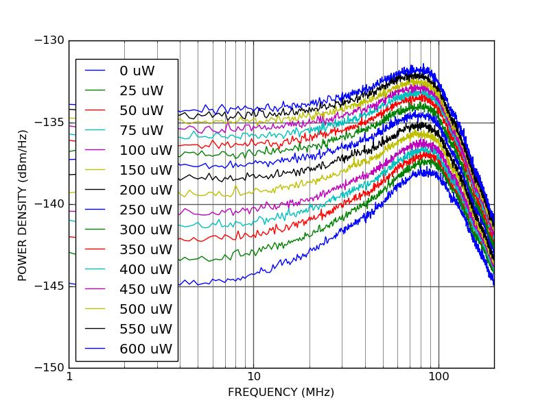
Schematic of photodetector noise components and their relationship with SNR
II. Core Principles: Four Main Noise Sources + Other Minor Ones
A photodetector’s noise comes mainly from four sources. Like four “troublemakers,” each has its own temperament.
1. Shot Noise
Shot noise arises from the particle nature of light and is an inevitable consequence of quantum mechanics.
Principle: Light is not a continuous wave but is composed of individual photons. The times at which photons arrive at the detector are random — even if the intensity is perfectly constant, the number of photons arriving per unit time fluctuates. This fluctuation is shot noise.
Mathematical expression:
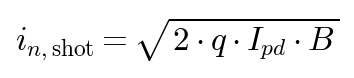
where:
- q = electron charge (1.6×10⁻¹⁹ C)
- I_pd = photocurrent (average current)
- B = measurement bandwidth
Characteristics:
- Shot noise is proportional to the square root of the photocurrent — the stronger the light, the greater the shot noise (but the SNR actually improves, because the signal grows linearly)
- Shot noise is white noise — uniform at all frequencies
- Shot noise is the quantum limit and can never be completely eliminated; you can only get close to it
A vivid analogy for shot noise: imagine raindrops hitting a window. The average intensity of the rain is steady, but at any instant the number of drops landing on the glass is random. The more drops (the stronger the light), the larger the absolute fluctuation, but the smaller the relative variation.
2. Thermal Noise (Johnson–Nyquist Noise)
Thermal noise arises from the thermal motion of electrons in a resistor.
Principle: As long as the temperature is above absolute zero, free electrons in a resistor are in constant Brownian motion, and this random motion produces random voltage fluctuations across the resistor. The detector’s equivalent load resistance and the preamplifier’s input resistance both generate thermal noise.
Mathematical expression:

or expressed as current noise: I_n,thermal = V_n,thermal / R = √(4 × k × T × B / R)
where:
- k = Boltzmann constant (1.38×10⁻²³ J/K)
- T = absolute temperature (K)
- R = resistance (Ω)
- B = measurement bandwidth
Characteristics:
- Thermal noise is also white noise, independent of frequency
- The higher the temperature, the greater the thermal noise — hence cooling reduces it
- The larger the resistance, the greater the voltage noise but the smaller the current noise (an important trade-off)
3. 1/f Noise (Flicker Noise)
1/f noise, as its name suggests, means the noise power spectral density is inversely proportional to frequency — large at low frequencies, small at high frequencies.
Principle: The physical origin of 1/f noise is complex, related to defects in semiconductor materials, carrier trapping and release, surface states and other factors. Put simply, there are “traps” in the material that occasionally capture or release carriers, causing slow fluctuations in current.
Characteristics:
- Noise power ∝ 1/f^α, with α typically between 0.8 and 1.2
- Dominant in the low-frequency band (usually below 1 kHz–10 kHz)
- 1/f noise has a “corner frequency”; above this frequency, 1/f noise is overwhelmed by shot noise and thermal noise
- 1/f noise varies greatly among materials and processes — a good photodiode may have a 1/f corner as low as a few tens of hertz, while a poor one may reach several kilohertz
Why is 1/f noise called “flicker noise”? Because when first observed in vacuum tubes, it caused slow flickering of the current. Interestingly, 1/f noise is everywhere — music, heartbeats, stock markets and earthquakes all show a 1/f spectral signature, known as “pink noise.”
4. Dark Current Noise
Dark current is the current a detector still outputs when there is no light at all.
Principle: Dark current arises mainly from thermal excitation — even without light, thermal motion in the PN junction generates electron–hole pairs which, separated by the built-in field, form a current. The higher the temperature, the larger the dark current.
Dark current itself is a DC offset, but the noise it brings is the bigger problem — dark current also has shot noise:
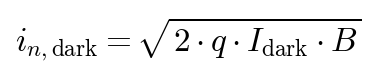
Characteristics:
- Dark current depends exponentially on temperature — it roughly doubles for every 7–10 °C rise (about 7 °C for silicon, about 10 °C for InGaAs, depending on material and process) [(RF Essentials – Dark Current)](https://rfessentials.com/resources/rf-glossary/dark-current/)
- Dark-current noise is one of the main limiting factors in weak-light detection
- Cooling can significantly reduce dark current (which is why high-end detectors are always cooled)
5. Other Noise Sources (minor, for awareness only)
- Generation–recombination noise (G-R noise): random fluctuations in the generation and recombination of carriers in a semiconductor, more pronounced in photoconductive detectors
- Temperature noise: random fluctuations in the temperature of thermal detectors (such as pyroelectric detectors and bolometers)
- Amplifier noise: voltage and current noise of the subsequent amplification circuit
- Environmental noise: power-supply ripple, electromagnetic interference (EMI), mechanical vibration, etc.
III. Key Parameters and Metrics
1. Signal-to-Noise Ratio (SNR / Signal-to-Noise Ratio)
SNR is the ratio of signal power (or the square of current/voltage) to noise power, usually expressed in decibels (dB):

Why is SNR so important? Because it directly determines measurement accuracy. Generally:
- SNR > 10 (about 20 dB): signal clearly distinguishable, measurement fairly accurate
- SNR > 100 (40 dB): the level of high-precision measurement
- SNR < 1 (below 0 dB): signal completely buried in noise, requiring other means (such as a lock-in amplifier) to extract it
2. Noise Equivalent Power (NEP / Noise Equivalent Power)
NEP is the incident optical power required to make the SNR equal to 1. In other words, the optical power the detector can “just barely sense.”
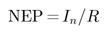
where:
- I_n = total noise current (usually taken at 1 Hz bandwidth)
- R = responsivity (A/W)
The unit of NEP is W/√Hz, expressing the noise-equivalent power at a 1 Hz measurement bandwidth. For an actual measurement bandwidth B, the equivalent noise power = NEP × √B.
The smaller the NEP, the more sensitive the detector. Typical values:
- Ordinary silicon photodiode: ~10⁻¹³ to 10⁻¹⁴ W/√Hz
- High-quality APD: ~10⁻¹⁴ to 10⁻¹⁵ W/√Hz
- PMT (photomultiplier tube): ~10⁻¹⁵ to 10⁻¹⁶ W/√Hz
3. Detectivity (D / Detectivity) and Specific Detectivity (D*)
NEP has a problem: the larger the detector area, the larger the noise usually is (because dark current is proportional to area). This makes detectors of different areas hard to compare directly.
Hence specific detectivity D* (pronounced “D-star”), which normalises for area:

where A is the detector area and Δf the bandwidth.
The unit of D is cm·√Hz / W (Jones). The larger the D, the better the detector performance.
D* is a very useful metric because it removes the effects of detector area and measurement bandwidth, allowing fair comparison of the intrinsic sensitivity of different detectors. Just as a running race is divided by distance, specific detectivity is “sensitivity after standardisation.”
4. Noise Equivalent Power vs. Minimum Detectable Power
Many people confuse NEP with “minimum detectable power,” but they are not the same thing:
- NEP is the power at SNR = 1 — at this point the signal is as large as the noise and you cannot tell which is which
- In practice, SNR ≥ 3 or even ≥ 10 is usually required for reliable detection
- So minimum detectable power ≈ 3–10 × NEP (depending on the required SNR)
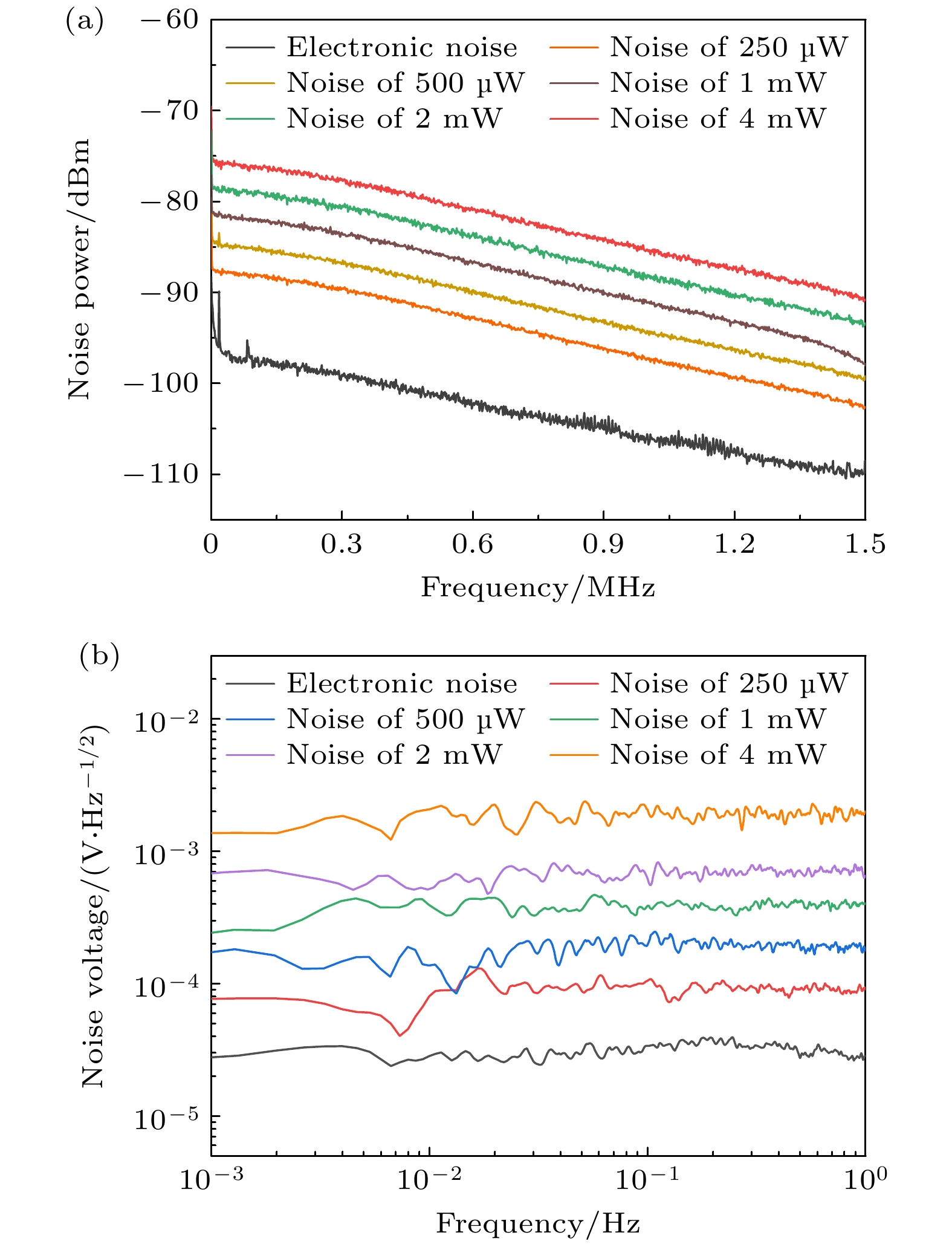
Typical photodetector noise spectrum distribution curve
IV. Common Misconceptions
Misconception 1: The less noise the better, so the narrower the bandwidth the better
No. Noise is indeed proportional to the square root of bandwidth (√B), and narrowing the bandwidth does reduce noise, but the signal is affected too — if your signal changes quickly (such as a short pulse), too narrow a bandwidth will distort the signal or even make it undetectable.
The correct approach: just enough bandwidth, without excessive margin. For example, to measure a 10 ns pulse, a 100 MHz system bandwidth is sufficient — there is no need for a 1 GHz amplifier; the extra bandwidth only adds noise.
Misconception 2: Gain can pull a weak signal out of the noise
Many people think: signal too weak? Just add an amplifier? Completely wrong. An amplifier amplifies the signal and the noise together, and the amplifier itself adds extra noise. Think of it this way: speaking through a megaphone in a noisy room — your voice gets louder, but the background noise gets louder too, and the SNR may even get worse.
The methods that genuinely improve SNR are:
- Reduce the noise source (cool to lower dark current, use a low-noise amplifier)
- Use modulation + lock-in amplification (move the signal to high frequency, avoiding 1/f noise)
- Increase optical power (at the shot-noise limit, SNR is proportional to the square root of optical power)
- Averaging / integration (signal adds coherently, noise incoherently; after N averages the SNR improves by √N)
Misconception 3: An APD, having gain, must be noisier than a PD
Not necessarily. An APD (avalanche photodiode) does have gain noise (excess noise factor F), but it depends on what you compare with. If the incident light is very weak, an ordinary photodiode’s signal may be drowned out by the amplifier’s input current noise, whereas the APD’s gain amplifies the signal first, making the amplifier noise relatively unimportant. In that case the APD’s overall SNR may actually be better.
It is like reception: if the signal is too weak, adding a low-noise amplifier (LNA) at the antenna gives a better overall result than amplifying later — because the signal is lifted first and downstream noise becomes relatively small. The APD plays this “front-end amplification” role.
Misconception 4: Cooling always reduces noise, and colder is always better
Cooling does work against dark current — as temperature drops, dark current falls exponentially. But if you are shot-noise limited (with a fairly strong optical signal), cooling does little, because shot noise is independent of temperature.
Moreover, cooling has costs:
- The cooler (TEC) itself generates heat and needs thermal management
- Too low a temperature may cause condensation, requiring sealing and desiccant
- Cost and power consumption both increase
So do not blindly pursue the lowest temperature — find the temperature at which dark current is small enough. For example, an InGaAs detector usually only needs cooling to −20 °C to −40 °C; below that the marginal benefit diminishes.
V. Selection Advice
1. First Determine Your Noise-Limiting Mechanism
Different applications are limited by different noise sources:
- Dark-current-noise limited: extremely weak light, DC or low-frequency measurement → prioritise low-dark-current detectors and consider cooling
- Shot-noise limited: light not too weak, SNR determined mainly by photon number → choose high-responsivity, low-excess-noise detectors
- 1/f-noise limited: very low frequency (<10 Hz), DC measurement → choose low-1/f devices or consider AC modulation
- Amplifier-noise limited: very small photocurrent (below nA) → choose detectors with internal gain (APD, PMT) or use a low-noise preamplifier
2. Select by Key Metrics
- Main concern sensitivity → look at D* (specific detectivity) and NEP
- Main concern speed → look at bandwidth and rise time
- Measuring extremely weak light → consider APD or PMT
- Measuring DC signals → pay special attention to 1/f noise and dark-current drift
- High-precision measurement → pay attention to long-term noise stability
3. Practical Noise-Optimisation Tips
- Choose the right bandwidth: not too wide, just enough to pass the signal
- Shielding and grounding: reduce extra noise from electromagnetic interference (EMI)
- Modulation/demodulation: use a chopper or modulator to move the signal to high frequency, avoiding 1/f noise
- Filtering: use appropriate low-pass or band-pass filters to remove out-of-band noise
- Averaging/integration: averaging multiple measurements improves SNR (by √N)
- Differential measurement: use two detectors in differential mode to suppress common-mode noise
- Temperature control: for dark-current-sensitive applications, add TEC temperature control
VI. Application Scenarios
1. Weak-Light Detection
- Single-photon detection: quantum communication, quantum computing, fluorescence-lifetime imaging — requires extremely low noise
- Raman spectroscopy: Raman scattering signals are very weak, requiring high-sensitivity detectors
- Biofluorescence: fluorescently labeled biological samples emit weakly, so SNR is key
2. Optical Communication
- Optical receiver sensitivity is directly limited by noise
- In high-speed communication, the trade-off between amplifier noise and shot noise is very important
- Sensitivity is usually expressed as “received power at a bit-error rate (BER) of 10⁻¹²”
3. LiDAR and Rangefinding
- Echo signals can be extremely weak (distant targets)
- Detector noise directly determines the maximum detection range
- In pulse mode, the effect of noise on timing accuracy must also be considered
4. Precision Measurement
- Precision optical measurements such as interferometry and ellipsometry
- Noise determines the resolution and repeatability of the measurement
- A lock-in amplifier is usually needed to extract signals deeply buried in noise
5. Infrared Detection
- Infrared detectors (HgCdTe, InSb, etc.) have more serious dark-current problems than visible-light detectors
- Liquid-nitrogen cooling (77 K) or even lower is usually required
- D* is the core metric for evaluating infrared detector performance
VII. Recommended Reading
- [What Is a Photodiode? The Most Basic Photodetector](https://www.soar-laser.cn/en/photodiode-encyclopedia/)
- [What Is an Avalanche Photodiode? A High-Sensitivity Detector with Built-In Gain](https://www.soar-laser.cn/en/apd-avalanche-photodiode-encyclopedia/)
- [What Is a Photomultiplier Tube? Why It Can Detect Single Photons](https://www.soar-laser.cn/en/pmt-photomultiplier-tube-encyclopedia/)
- [What Is an Optical Power Meter? How to Measure Laser Power Accurately](https://www.soar-laser.cn/en/optical-power-meter-encyclopedia/)
- [What Is a Laser Energy Meter? How to Measure Pulsed Laser Energy](https://www.soar-laser.cn/en/laser-energy-meter-encyclopedia/)
References:
- RP Photonics Encyclopedia – [Noise of Photodetectors](https://www.rp-photonics.com/noise_of_photodetectors.html)
- A. Yariv, “Optical Electronics”
- Thorlabs – Detector Noise Technical Documentation
- Hamamatsu Photonics – Photodiode Noise Characteristics
Leave a Reply