


What Is Fibre Coupling? How to Get Laser Light Efficiently into a Fibre
Fibre coupling is the process of getting light efficiently into a fibre from another optical element such as a laser, a free-space beam, a second fibre or a waveguide. The coupling efficiency sets the optical power budget of the whole system, and because the core of a single-mode fibre is only a few micrometres across, the beam quality, the alignment accuracy and the cleanliness of the end face all have to meet high standards. The sections below cover the mode matching, the key parameters, the common coupling schemes and the engineering applications.
Table of contents
- 1. What is fibre coupling? Getting the core concept straight
- 2. Working principle: how fibre coupling is achieved
- 3. Key parameters: reading the specifications of fibre coupling
- 4. Main types: what kinds of fibre coupling are there
- 5. Applications: where is fibre coupling used?
- 6. Common misconceptions: pitfalls to avoid
1. Core concept: what is fibre coupling?
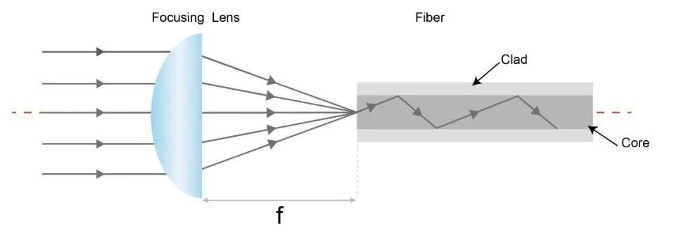
Fibre coupling is the process of getting light efficiently into a fibre from another optical element (a laser, a free-space beam, another fibre, a waveguide and so on). It is one of the most basic and most critical operations in fibre optics — the coupling efficiency directly affects the optical power budget and the performance of the whole system. Coupling may look as simple as pointing the light at the fibre end face, but in practice it involves mode matching, beam shaping, precise alignment and anti-reflection. It is particularly challenging for single-mode fibre, where the core is only a few micrometres across and both the beam quality and the alignment accuracy have to be very high.
2. Working principle: how is fibre coupling achieved?
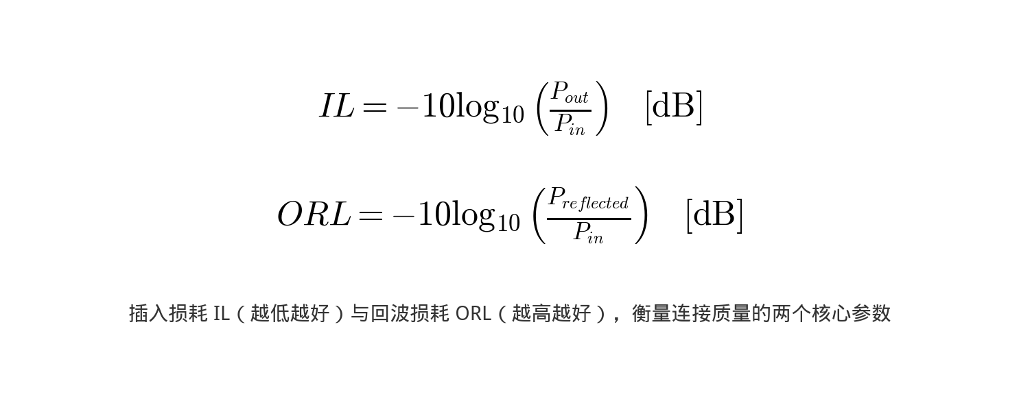
Insertion loss and return loss
The insertion loss (IL) is the optical power lost because of the coupling or the connection, expressed in dB. The lower the IL the better. A fusion splice typically gives 0.02-0.1 dB, while a connector typically gives 0.2-0.5 dB.
The return loss (return loss / optical return loss, ORL) is the ratio of the power reflected back to the input port to the incident power, taken as a negative logarithm. The higher the ORL the better — a high return loss means little reflection. Reflected light affects the stability of the laser, and DFB lasers in particular are very sensitive to it.
The essence of fibre coupling is mode matching — the complex amplitude distribution of the incident light (both intensity and phase) has to match the field distribution of the guided mode of the fibre as closely as possible, and only then is the coupling efficiency at its highest. Mathematically the coupling efficiency is the square of the overlap integral of the two mode fields.
For a single-mode fibre the coupling efficiency is highest when the incident beam is a perfect Gaussian and the beam waist radius, the position and the wavefront curvature at the fibre end face all match the fundamental mode of the fibre exactly. In practice the following conditions have to be met:
1. The beam quality of the source is close to the diffraction limit (M² ≈ 1)
2. The beam is focused at the fibre end face to a spot size that matches the mode field diameter
3. The wavefront is flat (that is, the focus lies exactly on the fibre end face)
4. The centre of the spot is precisely centred on the core (the positional error is far smaller than the mode field radius)
5. The angle of incidence is exactly aligned with the fibre axis (the angular error is far smaller than the beam divergence)
Both the lateral offset and the angular error reduce the coupling efficiency. For a Gaussian beam coupled into a single-mode fibre, the coupling loss caused by a lateral offset Δx can be calculated with the formula η = 4w₁²w₂²/(w₁²+w₂²)² × exp(-2Δx²/(w₁²+w₂²)), where w₁ and w₂ are the radii of the two mode fields. The effect of the angular error gets worse as the mode field area grows — a large mode area fibre has a smaller angular tolerance.
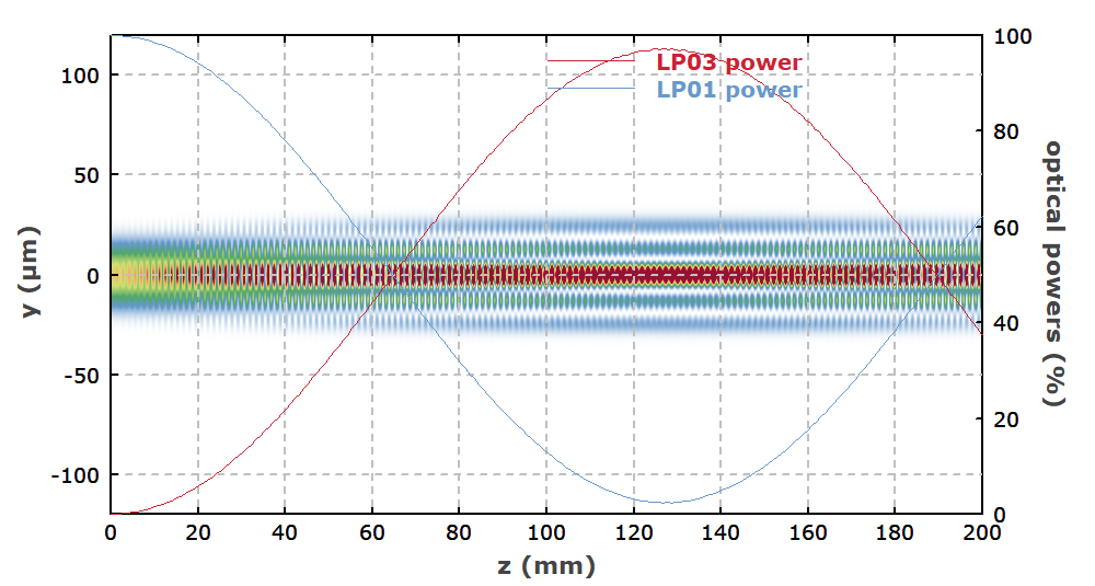
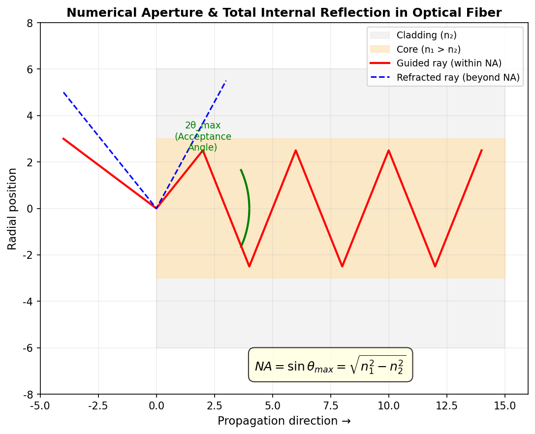
For a multimode fibre the coupling is comparatively simple — as long as the numerical aperture of the incident light does not exceed the NA of the fibre and the spot size does not exceed the core, most of the light can be coupled in. The coupling efficiency of a multimode fibre does, however, also depend on the mode distribution, which makes the situation more complicated than a simple geometric fill factor can describe.
3. Key parameters: reading the specifications of fibre coupling
Core formulas
Coupling efficiency of a Gaussian beam into a single-mode fibre: when the incident beam is Gaussian with a mode field radius of w₀ and the fibre mode field radius is w_f, the maximum coupling efficiency under ideal alignment is:
η_max = [2w₀w_f / (w₀² + w_f²)]²
When w₀ = w_f (a perfect mode field match), η_max = 100%.
Lateral offset loss: when the fibre end face is laterally offset by d, the coupling efficiency becomes:
η = η_max · exp[-2d² / (w₀² + w_f²)]
The smaller the mode field diameter, the smaller the alignment tolerance — the alignment accuracy required of a single-mode fibre (MFD ~10 μm) is far tighter than for a multimode fibre.
Angular error loss: the reduction in coupling efficiency caused by an angular error Δθ in the incident beam:
η = η_max · exp[-(π·w_f·Δθ·n/λ)²]
The smaller the numerical aperture NA of the fibre, the more accurate the angular alignment has to be.
Reading the key parameters is the starting point for assessing the performance of fibre coupling. The table below sets out the main specifications and what they mean:
| Parameter | Meaning | Engineering significance |
|---|---|---|
| Coupling efficiency | The ratio of the power coupled into the fibre to the incident power, usually given as a percentage or in dB | The fraction of the incident power that ends up in the fibre; it is the central performance figure |
| Insertion loss | The power loss caused by the coupling, in dB, with insertion loss = -10×log₁₀(coupling efficiency) | It sets how much power is lost at the coupling point and has to be budgeted into the optical power margin of the system. |
| Return loss | The ratio of the power reflected back towards the source to the incident power, in dB | It measures how much light is reflected back towards the source, and the higher it is the better it is for the stability of the laser. |
| Positional alignment tolerance | The lateral offset at which the efficiency falls to a given threshold (such as 1 dB) | The lateral alignment tolerance sets how finely the fibre mount has to be adjusted and therefore how long the alignment takes. |
| Angular alignment tolerance | The tilt angle at which the efficiency falls to a given threshold | The smaller the angular tolerance the harder the alignment; in systems with a large NA the angle usually runs out of margin first. |
| Mode field mismatch loss | The inherent coupling loss caused by two fibres having different mode field diameters | The larger the difference in mode field between the two fibres, the higher this inherent loss, and it usually cannot be removed by better alignment. |
The lenses used in fibre coupling
In free-space-to-fibre coupling the lens focuses the beam onto the fibre end face and makes the parameters of the focused beam (waist radius, divergence) match the mode field and the NA of the fibre.
The coupling lenses in common use are:
- Spherical lenses: cheap, suitable for multimode fibre coupling; the single-mode coupling efficiency is only moderate
- Aspheric lenses: the aberration is well corrected and the coupling efficiency is high, which makes them the first choice for single-mode fibre coupling
- Graded-index (GRIN) lenses: the end face is flat and can be bonded directly to the fibre; small in size and suitable for miniature optical modules
- Objective lenses: high numerical aperture, used for coupling into very small mode fields or into waveguides
The coupling efficiency into a single-mode fibre is extremely sensitive to the alignment accuracy — a lateral offset of 1 μm can already cause a noticeable loss. For the detailed analysis and the calculation methods, see the Fibre Coupling Technology and Coupling Efficiency article.
4. Main types: what kinds of fibre coupling are there?
Comparison of the common fibre coupling schemes
| Coupling scheme | Principle | Typical efficiency | Where it is used |
|---|---|---|---|
| Butt coupling (direct) | Two fibre end faces are aligned and brought into contact | Single mode <10%, multimode ~30% | Temporary testing |
| Fusion splicing | The two fibres are fused together by an electric arc | Single mode >95% (matched fibres) | Permanent connection |
| Lens coupling | A focusing lens brings the beam down onto the fibre end face | Single mode 60-85% | Free space → fibre, laser → fibre |
| Tapered fibre coupling | The fibre is tapered as a transition | >90% | Transition between fibres with different mode fields |
| Microlens fibre | The fibre end face is machined into a microlens | 70-90% | Laser chip → single-mode fibre |
Techniques for raising the coupling efficiency: make sure the incident beam is good (TEM₀₀ mode), use a lens with a matching NA, align precisely in three dimensions (with a fibre mount), keep the end face clean and undamaged, and consider an anti-reflection coating (which removes about 4% of Fresnel reflection loss).
Fibre coupling can be classified in many ways, and each dimension helps you understand its characteristics from a different angle. The most common ones are introduced below:
By what is being coupled
Free-space to fibre coupling
A free-space beam is coupled into the fibre with a focusing lens, which needs an alignment mechanism
Fibre to fibre coupling
The light of one fibre is coupled into another, by fusion splicing, a mechanical butt joint or lens coupling
Waveguide to fibre coupling
Coupling an integrated photonic chip to a fibre, using a grating coupler or an edge coupler
By implementation
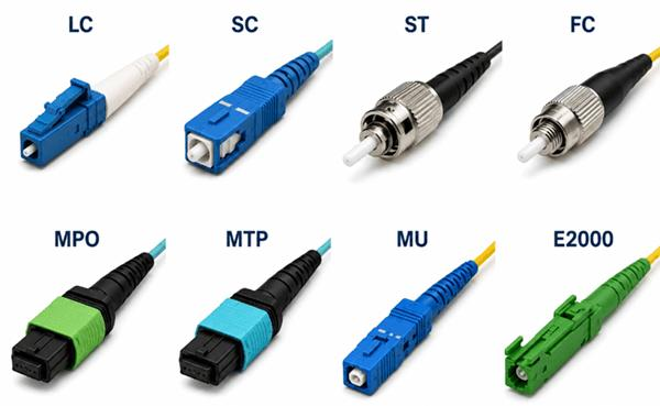
Fusion splice vs mechanical splice vs connector
There are three main ways of connecting one fibre to another, each with its own characteristics:
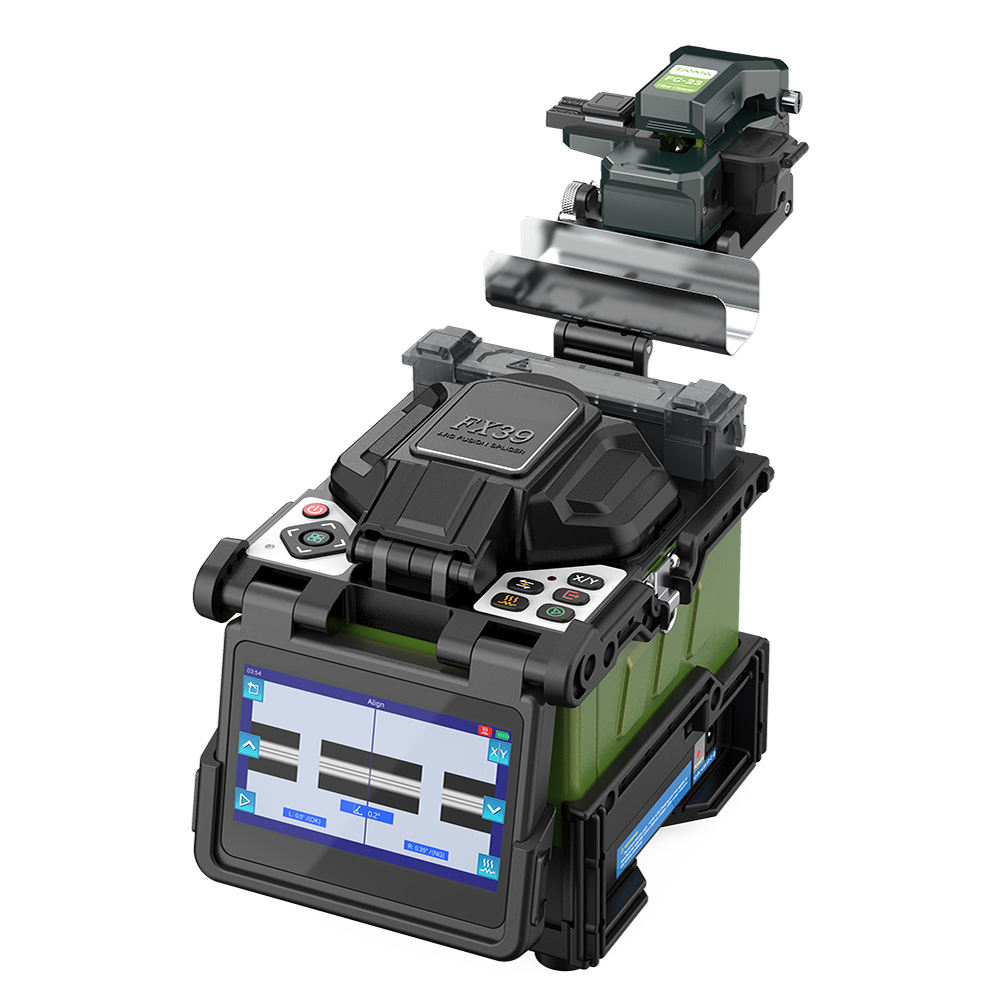
- Fusion splicing: the two fibre end faces are welded together with an arc. The advantages are the lowest loss (< 0.1 dB), the smallest reflection (> 60 dB) and the highest reliability. The disadvantages are that it needs dedicated equipment (a fusion splicer), that the operation is relatively involved and that the joint cannot be dismantled.
- Mechanical splicing: the two fibres are aligned in a precision V-groove and fixed with index-matching gel. The advantages are simple equipment and easy on-site work. The disadvantages are a higher loss (0.1-0.3 dB) and a long-term reliability that is below that of a fusion splice.
- Connectors: the fibres are butted together through the connector plug and the adapter. The advantages are that they are pluggable and flexible, which makes maintenance and testing easy. The disadvantages are the largest loss (0.2-0.5 dB), a lower return loss and end faces that are easily contaminated.
FC/PC vs FC/APC: the difference in the end-face polish
The end-face geometry of a fibre connector has a huge effect on the return loss:
PC (physical contact): the end face is spherical, so that the cores of the two fibres make physical contact. The typical return loss is about 40-50 dB.
APC (angled physical contact): the end face is a spherical surface with an 8° angle, so the reflected light is directed into the cladding instead of straight back. The typical return loss is > 60-65 dB, far better than the PC type. APC connectors usually have a green end face, while PC connectors are blue or black.
💡 Why can an APC not be mated with a PC?
The APC end face is angled at 8° and the PC end face is a perpendicular spherical surface. If an APC is mated with a PC the end faces cannot touch, which produces a large insertion loss (possibly > 1 dB) and an air gap, and the performance suffers badly. Both ends must always be of the same connector type in practice.
Fusion coupling
The two fibres are fused together with an arc, which gives the lowest loss (< 0.1 dB) and a permanently reliable joint
Mechanical alignment coupling
The two fibres are butted together in a precision fixture; it can be dismantled, at a slightly higher loss
Lens coupling
One or more lenses shape and focus the beam, which allows efficient coupling between fibres with different mode fields
Tapered coupling
The fibre is tapered to change the mode field size, which converts the mode field
By the optical element used
Single-lens coupling
An aspheric or GRIN lens is used, so the structure is simple
Two-lens coupling
Two lenses form a telescope arrangement, which gives a larger alignment tolerance
Fibre collimator
A device that collimates the light coming out of a fibre into a parallel beam; it is the reverse of coupling
5. Applications: where is fibre coupling used?
The applications of fibre coupling span several fields; the main directions are:
- Fibre laser systems: coupling the pump light into the gain fibre, coupling the seed light and connecting the amplifier stages all need efficient fibre coupling
- Optical communication systems: the coupling of the laser into the transmission fibre, the signal coupling inside the optical amplifier and the photodetector coupling at the receiving end
- Fibre sensing systems: coupling the source to the sensing fibre and coupling the sensing signal to the detector
- Optical measurement instruments: devices such as the optical power meter, the spectrometer and the optical time domain reflectometer (OTDR) all need a fibre-coupled input
- Integrated photonics: the coupling of a silicon photonic chip to an external fibre is a key technology and directly affects the insertion loss of the device
- Medical and industrial laser systems: the light of the laser source is coupled into a delivery fibre and then sent to the surgical or the processing head
👉 Want to see more real application cases? Visit the application case page of Soar Laser, or contact our technical team directly for professional advice.
6. Common misconceptions
Misconception 1: a low coupling efficiency means it is only a misalignment
Alignment is only one of the factors behind the coupling efficiency. A low efficiency can have other causes: the spot size does not match the mode field of the fibre (mode field mismatch), the convergence angle is too large for the numerical aperture of the fibre (NA mismatch), the lens aberration is too strong, the fibre end face is dirty or damaged, the incident beam quality is poor (M² too high), or the wavefront carries astigmatism. The right order of diagnosis is: first check whether the optical design is sound, then check the end-face quality, and only then do the fine alignment.
Misconception 2: the more lenses you use, the higher the coupling efficiency
Not necessarily. With more lenses the aberration may be better corrected, but every extra lens adds two reflecting surfaces — each interface reflects about 4% (if it is not coated), which is a substantial loss. More lenses also make the assembly harder and let the alignment errors accumulate. For most applications a single high-quality aspheric lens is enough and reaches a coupling efficiency of 80-90% or better.
Misconception 3: the larger the NA of the fibre, the easier the coupling
That is largely true for a multimode fibre: the larger the NA the wider the acceptance angle and the easier the light gets in. A single-mode fibre is different — the NA and the mode field diameter are linked, and a single-mode fibre with a large NA usually has a smaller mode field diameter, which needs a smaller focus and therefore makes the alignment harder. A single-mode fibre with too large an NA also has a higher bend loss.
Misconception 4: fibre coupling is only about raising the power
The purpose of fibre coupling depends on the application and goes well beyond raising the power. The common purposes include: converting free-space light into a flexible delivery path (useful when the optical path has to be rearranged in a laboratory), using the mode cleaning effect of the fibre (the spatial distribution of the light coming out of a multimode fibre is more uniform), distributing the beam flexibly (splitting and combining it) and matching it to the downstream fibre components (isolators, amplifiers). Power is only one of the dimensions.
7. Recommended reading
- What is an optical fibre? How light travels thousands of kilometres in a glass thread
- Fibre coupling technology and coupling efficiency
- What is a fused fibre coupler? How two fibres split light
- What is a laser mode? What do transverse and longitudinal modes mean?
- What is a fibre laser? Why it dominates the industrial laser market
- What is an optical power meter? How to measure laser power accurately
Leave a Reply