


Laser Beam Shaping Technology
I. Overview
Most lasers output beams with a Gaussian distribution — brightest at the centre, gradually dimming toward the edge. Gaussian beams have advantages (smallest focused spot, M² factor near 1), but in many applications a Gaussian distribution is not the best choice.
For laser heat treatment, you want the irradiated area to heat evenly, which a Gaussian distribution cannot do — the centre is too hot and the edge too cool. For laser cutting, sometimes you need a uniform line spot rather than a round dot. In laser medicine, to irradiate tissue evenly, a Gaussian distribution may burn the centre while the edge is under-treated.
That is when beam shaping technology is needed — transforming the original Gaussian beam into the intensity distribution you want.
A beam shaper (Beam Shaper), also called a beam converter (Beam Converter), is an optical device that changes a laser beam’s spatial intensity distribution. Common shaping goals include converting a Gaussian beam into a flat-top beam (flat-top / top-hat beam), or symmetrizing the output of a diode array.
A vivid analogy: beam shaping is like piping a cake — cream squeezed from a piping bag is naturally round, but swap in a star-shaped nozzle and it comes out star-shaped. A beam-shaping element is the “piping nozzle” for light, letting it be “squeezed” into the shape you want.
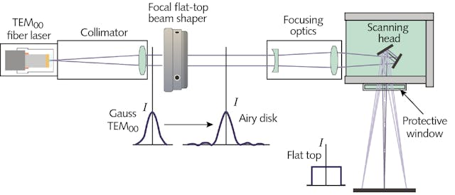
Figure 1: optical path from a fundamental-mode Gaussian beam reshaped by a shaper into a flat-top beam. Left is the original Gaussian distribution; after the shaping optics, a uniform flat-top intensity distribution forms on the target work plane.
II. Working principles
1. Why is beam shaping needed?
First consider: why are most laser beams in nature Gaussian? Because the Gaussian distribution is the lowest-loss mode of a spherical-mirror resonator and the “most shape-stable” distribution in free-space propagation — a Gaussian beam stays Gaussian as it propagates, only changing size.
But application needs are diverse. According to RP Photonics, common shaping needs include:
| Application | Required beam shape | Reason |
|---|---|---|
| Laser heat treatment / annealing | Flat-top spot | Uniform heating, avoiding centre overheating |
| Laser processing (marking, welding) | Flat-top or line spot | Uniform energy distribution, consistent processing quality |
| Semiconductor pumping | Symmetrized beam | Diode array output is asymmetric, needs shaping before pumping |
| Biomedical illumination | Flat-top spot | Uniform illumination, good imaging quality |
| Nonlinear frequency conversion | Flat-top beam | Avoid reverse conversion at high power, raise efficiency |
| Optical tweezers / particle manipulation | Ring beam | Needed for trapping particles |
2. What is a flat-top beam?
A flat-top beam (also called a top-hat beam) is a beam whose intensity distribution is flat over most of its area. This contrasts with a Gaussian beam, whose intensity falls smoothly from a central maximum to zero.
Flat-top beams are usually approximated by a supergaussian function:

where n is the supergaussian order; the larger n is, the steeper the edge and the closer to an ideal rectangular distribution.
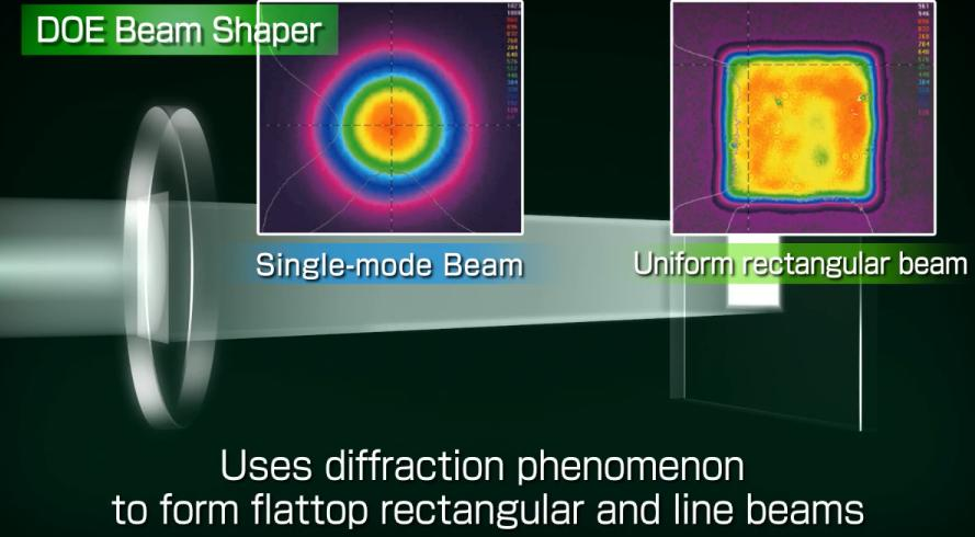
Figure 2: working principle of a diffractive optical element (DOE) beam shaper. Diffraction reshapes a single-mode Gaussian beam (left) into a uniform rectangular flat-top beam (right).
Note: a flat-top beam is not a natural free-space mode like the Gaussian beam — during propagation its intensity-distribution shape changes. The steeper the edge, the faster the shape changes. For beams with a large diameter and not-too-steep edges, the shape can stay approximately unchanged over a certain propagation distance.
3. Field-mapping beam shapers
Field-mapping (also called analytical) beam shapers use refractive or diffractive optics to redistribute the energy of a coherent single-mode input beam in a deterministic way. These devices preserve spatial coherence and wavefront quality, have a long depth of focus and no speckle. But they are very sensitive to the alignment, size and shape of the input beam.
RP Photonics mentions two main field-mapping technology routes:
(1) Refractive beam shapers
Use lens refraction to change the light’s intensity distribution. A common example is a system of two aspheric lenses (Aspheric Pair), which uses precisely designed curved surfaces to “remap” the incoming Gaussian distribution into a flat-top distribution.
- Advantages: high efficiency, high damage threshold, no higher-order diffraction
- Disadvantages: difficult design and fabrication, usually only for relatively simple shaping goals
(2) Diffractive beam shapers (DOE)
Use the diffraction effect of surface microstructures to shape the beam. A DOE can achieve very complex shaping goals because of its high design freedom.
- Advantages: extremely high design freedom, can generate almost any shape
- Disadvantages: sensitive to input-beam parameters, with higher-order diffraction and zero-order issues
4. Beam-integrator type (integration homogenization / fly’s-eye homogenization)
Beam integrator (Beam Integrator / Homogenizer), such as a microlens array or multi-faceted duct, splits the beam into many sub-beams and then superimposes them.
Working principle: incident light is split by the microlens array into many sub-beams; each sub-lens focuses or projects its portion, and they overlap at the target plane. Because many sub-beams superimpose, overall uniformity improves.
This method disturbs the wavefront and lowers spatial coherence, so it also works for multimode or unstable sources. But the drawbacks: if the source has some coherence, it produces interference patterns (speckle), and it usually works only at a specific working plane.
5. Diode-array beam shaping
The output of a diode laser bar (Diode Bar) is highly asymmetric — the fast axis (vertical) has a large divergence angle but good beam quality, while the slow axis (horizontal) has a small divergence angle but poor beam quality. Using cylindrical lenses alone can make the spot round but cannot make the beam quality equal in both directions.
The beam shaper’s task is to rearrange the beam so the fast- and slow-axis beam quality becomes symmetric while preserving brightness. Typical solutions include:
- Step mirror / reflective shaper: uses multiple mirrors to “stack” the emitters along the slow axis, making fast and slow axes symmetric
- Polarisation coupling: uses polarisation to combine beams
- Fibre-bundle shaping: couples each emitter into a fibre, rearranged as needed at the other end
6. Other shaping solutions
- Powell lens: a special aspheric cylindrical lens that produces a laser line with uniform intensity along its length. Its aspheric “roof” shape redistributes energy toward the line’s ends, avoiding the bright-centre/dim-edge problem of ordinary cylindrical lenses. Widely used in machine vision and 3D triangulation systems.
- Spatial light modulator (SLM): programmable beam shaping that adjusts the output beam shape in real time by electrically controlling the phase distribution. Common in research, but with low damage threshold.
- Galvo-scanning shaping: “draws” the desired spot shape through high-speed scanning (using heat accumulation or persistence of vision). Highly flexible, but strictly speaking not instantaneous shaping.
III. Key parameters and performance metrics
| Parameter | Meaning | Description |
|---|---|---|
| Shaping efficiency | Useful optical power / incident optical power | %, higher is better. High-quality DOE can reach 90%+ |
| Uniformity | How uniform the intensity distribution is within the spot | Often expressed as ±% (peak-to-valley) or RMS |
| Edge steepness | Width of the transition region at the flat-top edge | Steeper edges mean a larger M² factor |
| Energy utilisation | Main-lobe energy / total energy | %, reflects the share of stray light |
| Operating wavelength | Applicable wavelength range | nm |
| Damage threshold | Maximum laser power density it can withstand | W/cm² or J/cm² |
| Input-beam requirements | Requirements on input-beam parameters | Spot size, M², divergence angle etc. |
| Working distance | Distance from the shaping plane to the element | mm, affects system layout |
How is uniformity evaluated?
Uniformity is one of the most important beam-shaping metrics; common evaluation methods:
- Peak-to-valley (P-V, ±%): (max − min)/(max + min) × 100%, reflecting the greatest degree of non-uniformity
- RMS uniformity: root-mean-square deviation of the intensity distribution / average, reflecting overall uniformity
- Top flatness: uniformity within the middle 80% or 90% of the area (excluding the edge-transition region)
In general, uniformity within ±5% is considered good, and within ±2% is fairly high-end.
IV. Main types / classification
1. By working principle
| Type | Representative device | Coherence | Efficiency | Uniformity | Flexibility | Power handling |
|---|---|---|---|---|---|---|
| Refractive field mapping | Aspheric lens pair | Preserves coherence | Very high | High | Low | High |
| Diffractive field mapping | DOE diffractive optical element | Preserves coherence | High | Very high | Medium | Medium–high |
| Integration homogenization | Microlens array, fly’s-eye | Reduces coherence | Medium–high | Medium | Low | High |
| Scattering / diffusing | Diffuser, homogenizing sheet | Greatly reduces coherence | Medium | Medium | Low | High |
| Dynamic programmable | SLM spatial light modulator | Controllable | Low–medium | High | Highest | Low |
| Scanning type | Galvo scanning | Preserves coherence | — | High | Highest | Depends on galvo |
2. By shaping goal
- Flat-top beam shaper: Gaussian → flat-top (circular, square, rectangular)
- Beam splitter / dot array: one beam → multiple beams (regularly arranged dot array)
- Line-spot generator: Gaussian → uniform line spot (Powell lens etc.)
- Ring beam / vortex beam: Gaussian → ring (axicon, spiral phase plate)
- Beam symmetrization: asymmetric beam (e.g. diode array) → symmetric beam
V. Typical application scenarios
1. Laser processing
- Laser heat treatment / annealing: flat-top beams for uniform heating, ensuring consistent material properties
- Laser welding: flat-top spots have more uniform energy distribution and more stable weld quality
- Laser drilling: specially shaped spots can drill shaped holes
- Laser cleaning: line or flat-top spots improve cleaning efficiency and uniformity
- Laser marking / 3D printing: galvo-scanning shaping, highly flexible
2. Semiconductors and research
- Laser annealing: uniform line spots for wafer annealing
- Lithography illumination: specific illumination shapes (e.g. ring, dipole) improve resolution and depth of focus
- Nonlinear frequency conversion: flat-top beams at high power avoid reverse conversion and raise conversion efficiency
- Atom cooling and manipulation: specially shaped optical traps
3. Biomedicine
- Laser aesthetics: flat-top beams ensure even energy and avoid centre burns
- Ophthalmic surgery: precise control of spot shape and energy distribution
- Fluorescence-microscope illumination: uniform excitation illumination
- Optical tweezers and particle manipulation: specially shaped beams (ring, vortex) to manipulate microparticles
4. Laser display and illumination
- Laser projection: needs uniform illumination spots, or the image is bright in the centre and dim at the edges
- Stage lighting: various laser-beam shape effects
- Automotive headlights: laser headlights need specific light-shape distributions
5. LiDAR and sensing
- LiDAR illumination: uniform spot covers the target area, improving detection consistency
- Distributed sensing: special beam distributions optimise sensing performance
VI. Common myths
Myth 1: Any incident light can be shaped
Wrong. Every shaping element is designed for a specific input beam. For a DOE, if your input spot size differs from the design value by 20%, the shaping effect degrades markedly — wrong spot shape, poorer uniformity, lower efficiency.
Correct approach: when choosing a shaping element, always confirm its design input parameters (spot size, divergence angle, M², wavelength) match your actual beam.
Myth 2: A flat-top spot is completely uniform
There is no absolutely uniform flat-top spot in the world. A real flat-top beam usually has a fairly uniform middle region (the “flat top”), an edge transition region where intensity drops rapidly from high to zero, and small ripples within the flat top.
The width of the transition region is related to the input beam’s M² — the smaller the M², the steeper the transition; the larger the M², the gentler.
Myth 3: A flat-top beam keeps its shape during propagation
A flat-top beam is not a natural free-space mode. Unlike a Gaussian beam, a coherent flat-top beam’s shape changes during propagation — the steeper the edge, the faster the change, due to diffraction. Only within a certain working distance (depth of focus) is the flat top maintained.
Myth 4: 100% shaping efficiency is possible
For lossless shaping elements (e.g. DOE, lens arrays), efficiency can theoretically be very high but never 100%. Reasons: surface reflection (Fresnel reflection at each interface), absorption, stray light and higher-order diffraction, scattering. Commercial high-quality DOEs typically have 80–95% shaping efficiency.
Myth 5: All shaping methods are interchangeable
Different shaping methods suit different scenarios:
- Need high power → choose refractive or reflective, not SLM
- Need flexibility → choose SLM or galvo scanning, not a fixed DOE
- Need very high uniformity → choose DOE, better than a simple microlens array
- Need low cost → choose fibre homogenization or a simple lens solution
Select by your actual need — no single solution is universal.
VII. Selection advice
1. By application scenario
| Application | Recommended solution | Reason |
|---|---|---|
| High-power laser processing (cutting / welding / heat treatment) | Refractive shaper, high-power DOE | Needs high power handling |
| Laser marking / 3D printing | Galvo-scanning shaping | High flexibility, shape adjustable anytime |
| Research experiments (need flexible adjustment) | Spatial light modulator (SLM) | Programmable, most flexible |
| Laser display / illumination | Microlens array, DOE homogenizing sheet | Good uniformity, moderate cost |
| Optical tweezers / particle manipulation | DOE (vortex phase plate), SLM | Need special beam shapes |
| Laser medicine (aesthetics / ophthalmology) | DOE flat-top shaper | Good uniformity, high safety |
| Low-cost homogenization | Multimode fibre homogenization, diffuser | Low cost, modest uniformity requirement |
| Line-spot applications (machine vision etc.) | Powell lens | Uniform line spot, high efficiency |
2. By key requirement
- Highest uniformity requirement → choose high-precision DOE
- Highest power-handling requirement → choose refractive or reflective shaping
- Highest flexibility requirement → choose SLM or galvo scanning
- Lowest cost budget → choose microlens array or fibre homogenization
- Most complex spot shape → choose DOE or SLM
3. Selection cautions
- Confirm input-beam parameters: spot size, divergence angle, M² factor, wavelength — all must match the shaping element’s design values
- Mind power handling: high-power applications must confirm the damage threshold with ample margin
- Unify the uniformity-evaluation standard: when discussing uniformity with a supplier, specify whether it is peak-to-valley or RMS, and whether over the whole spot or the flat-top part
- Consider stray light: DOE zero-order and higher-order diffraction, microlens-array edge diffraction — these stray lights may matter in some applications
- Working distance and depth of focus: confirm the post-shaping working distance and depth of focus suit your system layout
- Trade-off between edge steepness and depth of focus: steeper edges mean shorter depth of focus (faster shape change in propagation), to be balanced by application need
VIII. Recommended reading
- RP Photonics: Beam Shapers (original)
- RP Photonics: Flat-top Beams (original)
- What is Laser Beam Quality? Why Some Lasers Focus Smaller
- What is a Gaussian Beam? The Standard Form of Laser Light
- M² Factor Explained: The International Standard Measure of Beam Quality
- What is a Beam Profile? Intensity Distribution Across a Laser’s Cross-Section
- Laser Scanning Galvo Scanner: Principles and Applications
- What is a Diffractive Optical Element (DOE)? Shaping Light by Diffraction
IX. References
- RP Photonics Encyclopedia – Beam Shapers (https://www.rp-photonics.com/beam_shapers.html)
- RP Photonics Encyclopedia – Flat-top Beams (https://www.rp-photonics.com/flat_top_beams.html)
- RP Photonics Encyclopedia – Beam Homogenizers
- RP Photonics Encyclopedia – Microlens Arrays
- RP Photonics Buyer’s Guide for Beam Shapers
Leave a Reply