


Galvanometer Scanners: Principles and Applications
I. Overview
You may have seen a laser marking machine — a laser beam “drawing” all kinds of patterns and text on metal or plastic, so fast it looks like magic. How can that beam change direction so nimbly? The answer is the galvanometer scanner.
A laser scanner is a class of device used to control the direction in which a laser beam exits. The galvo scanner (Galvanometer Scanner, galvanometer-type scanner) is the most commonly used and most representative of these. It is like the “steering wheel” of the laser: by rotating a small mirror at high speed it reflects the laser to different positions. Combine two galvos (an X axis and a Y axis) and the laser can scan freely across a plane, drawing all kinds of complex shapes.
The name “galvo” sounds a little old-fashioned; in full it is the “galvanometer scanner,” because the earliest galvanometers used a coil deflecting in a magnetic field to indicate the magnitude of a current. Today’s laser galvo scanners follow the same principle as those old galvanometers, but their precision and speed are many orders of magnitude higher.
An interesting comparison: shake a mirror by hand to reflect sunlight and the fastest you can manage is a few times per second. An industrial galvo scanner, by contrast, can swing back and forth thousands of times per second — at small angles even tens of thousands. And its positioning accuracy can reach the microradian level.
According to RP Photonics’ classification there are many kinds of laser scanner: besides galvos (galvanometer type), there are polygon scanners, acousto-optic deflectors (AOM scanners), electro-optic scanners, MEMS mirrors, optical phased arrays and others. Galvos are only one class, but because they are the most widely used in laser processing and laser marking, “laser scanning” in common usage largely means galvo scanning.
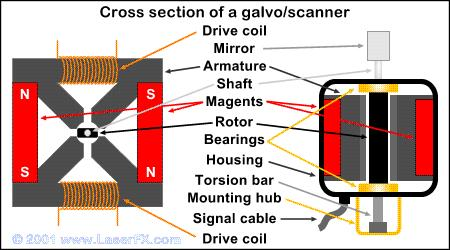
Figure 1: Cutaway view of the internal structure of a galvo scanner (galvanometer scanner). Core components include the drive coil, magnet, rotor, shaft, bearings, mirror and position sensor.
II. Operating Principle
1. Basic Structure of a Galvo Scanner (Galvanometer Scanner)
A typical galvo unit (single axis) consists of the following parts:
① Motor rotor (Rotor)
- the mirror is fixed on it
- usually a moving-magnet or moving-coil design
- a position sensor is also mounted on the rotor
② Stator and drive coil (Drive Coil)
- provides the magnetic field (permanent magnet)
- when the coil is energized it generates an electromagnetic torque that drives the rotor to rotate
③ Position feedback sensor
- detects the rotor angle in real time
- feeds the signal back to the drive circuit, forming closed-loop control
- high-end galvo position sensors can reach microradian-level resolution
④ Mirror
- bonded to the rotor, swinging together with it
- materials are usually quartz, silicon, silicon carbide or beryllium (light, hard, with good thermal conductivity)
- the surface is coated with a high-reflectance film for the corresponding wavelength
2. Other Types of Laser Scanner
According to RP Photonics Encyclopedia, laser scanners follow several technical routes:
(1) Rotating Mirror Scanner
The simplest kind: the angled end face of a cylinder is coated with a reflective film; a motor rotates the cylinder, and the incident laser is periodically reflected into different directions.
(2) Polygon Scanner
A polygonal prism whose every side is a reflective surface. The prism rotates continuously, with each face sweeping through a range of angles. Most scanners in laser printers are of this type.
- Advantage: high speed, can achieve very high scan frequencies
- Disadvantage: can only perform periodic uniform-speed scanning, cannot position arbitrarily
(3) Galvanometer Scanner (Galvanometer Scanner, galvo)
The scanning mirror can be rotated by electromagnetic force to different angular positions. Some operate in a mechanical resonance mode (resonant galvos), in which case the scan speed is not constant (sinusoidal motion).
- Advantage: can position at any angle, highly flexible
- Disadvantage: somewhat slower than polygon scanners
(4) MEMS Scanners
Micro-scale scanners based on MEMS (micro-electromechanical systems) technology, extremely small in size. Common in consumer-grade LiDAR, AR glasses and similar applications.
(5) Acousto-optic Deflector (AOD)
With no moving parts, it uses the diffraction effect of sound waves in a crystal on light to deflect the beam. The deflection angle is controlled by the applied radio-frequency signal.
- Advantage: extremely fast, no mechanical wear
- Disadvantage: small deflection angle range, limited number of resolvable spots
(6) Electro-optic Scanners
Use the electro-optic effect to deflect the beam; extremely fast, but the scan angle is usually very small.
(7) Optical Phased Array
Composed of a group of coherent emitting elements; by controlling the phase difference between elements, the exit direction of the combined beam is changed. It may be used in future miniature LiDAR for autonomous driving.
3. Dual-Galvo Scanning System
To scan across a plane you need two galvos working together — one for the X direction and one for the Y direction.
There are two common layouts:
- XY stacked type: the two galvos are arranged one behind the other, the X galvo in front and the Y galvo behind (or vice versa)
- Near-pupil type: the rotation axes of the two galvos are placed as close together as possible, forming a “virtual common pivot”
The key to a dual-galvo system is synchronised control of the two galvos — whether the path is drawn accurately depends entirely on how well X and Y cooperate. This requires a high-performance drive control board for real-time path planning and servo control.
For three-dimensional processing (such as marking on curved surfaces), a dynamic focusing unit (also called a “vario-scan” module) must also be added. This module contains a movable lens that rapidly adjusts the beam divergence during X-Y scanning, so the focus follows changes in the surface height.
4. F-Theta Lenses: Making Scanning Flat
Here is a very important problem: if the galvo merely rotates the mirror and changes the angle of the reflected light, then on a distant receiving surface the scan path is not a straight line but an arc — and the linear speed at the centre and at the edge is different too.
The F-theta lens is designed to solve this problem. It is a specially designed flat-field scanning lens whose characteristic is: image height 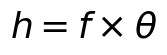 , that is, the image height is proportional to the scan angle
 (rather than the
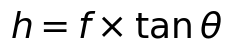 of an ordinary lens).
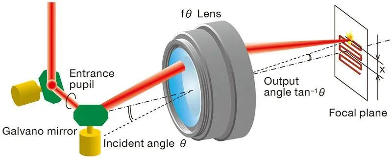
Figure 2: Operating principle of an f-theta scanning lens. The galvo changes the laser’s angle of incidence, and the f-theta lens converts angular scanning into linear displacement in the focal plane, ensuring uniform scan speed and that the focused spot always lies on the plane.
In this way, if the galvo rotates uniformly, the scan point moves at a uniform speed in the image plane, and the scanning surface is a plane.
5. Pre-Objective Scanning vs. Post-Objective Scanning
Depending on the order of the scanner and the focusing objective, there are two architectures:
- Pre-objective scanning (Pre-objective Scanner): the scanner is placed before the focusing objective. The objective must handle beams at different angles of incidence, for example using an f-theta scanning lens. This is the most common architecture.
- Post-objective scanning (Post-objective Scanner): the scanner is placed after the focusing objective, when the beam is already converging. In laser processing this scheme allows a smaller protective window that is easy to replace.
6. Reflective vs. Refractive Scanning
Most scanners use a movable mirror, but there are also schemes that use refractive elements to deflect the beam — for example rotating Risley prisms, or a laterally moving lens (the principle used in some fibre delivery systems).
III. Key Parameters and Performance Metrics
| Parameter | Meaning | Unit | Notes |
|---|---|---|---|
| Scan angle | Maximum angle the galvo can swing through | °, mrad | usually expressed as ±angle |
| Scan speed / response time | how fast the galvo is | μs | small-angle step response time |
| Positioning accuracy | accuracy of repeated positioning | μrad, μm | including linearity and repeatability |
| Spot drift | positional drift during long-term operation | μrad, μm | thermal drift is the main factor |
| Clear aperture | largest spot that can pass through the galvo | mm | sets the upper limit on spot size |
| Applicable wavelength | coating wavelength range of the mirror | nm | different wavelengths require different coatings |
| Damage threshold | maximum power density the mirror can withstand | W/cm², J/cm² | important for high-power applications |
Interpreting a Few Key Parameters
How do you read scan speed? A galvo’s speed is usually expressed as “small-angle step response time,” for example “100 μs (0.1° step)” — meaning it takes only 100 microseconds to rotate the galvo by 0.1 degree and settle. Galvos used in high-end marking machines achieve response times of 20–30 μs.
Why does spot drift matter? When a galvo is working, its motor coil heats up; the heat conducts to the rotor and mirror, causing thermal deformation and positional drift. If the drift is too large, long marking jobs will show “pattern wandering.”
IV. Main Types / Classification
1. By Drive Method
| Type | Principle | Speed | Positioning flexibility | Typical applications |
|---|---|---|---|---|
| Galvanometer galvo | electromagnetic force drives the mirror to rotate | Medium to high | High (any angle) | Laser marking, cutting, 3D printing |
| Resonant galvo | mechanical resonance, sinusoidal oscillation | Very high (kHz range) | Low (back-and-forth only) | High-speed imaging, laser displays |
| Polygon scanner | reflection from a rotating polygonal prism | Very high | Low (uniform-speed scanning) | Laser printing, high-speed barcode scanning |
| Acousto-optic deflector (AOD) | acousto-optic diffraction | Extremely high | Medium (small angular range) | Confocal microscopy, research |
| MEMS galvo | micro-electromechanical drive | High | Medium | Consumer-grade LiDAR, AR |
| Optical phased array | phase-controlled array | Extremely high | Medium | Solid-state LiDAR (emerging) |
2. By Scanning Dimension
- One-dimensional scanner: scans in only one direction (e.g. barcode scanners, laser printers)
- Two-dimensional scanner: X-Y directions, can scan freely across a plane (e.g. laser marking)
- Three-dimensional scanner: X-Y-Z directions, with dynamic focusing (e.g. curved-surface processing, 3D printing)
3. Subtypes of Galvanometer Scanners
- Moving-coil type: the coil moves, the magnet is fixed — high drive force, but high inductance limits speed
- Moving-magnet type: the magnet moves, the coil is fixed — low rotational inertia, high speed, the mainstream scheme
V. Typical Applications
1. Laser Marking
This is the largest application area for galvos. Almost all logos, QR codes, serial numbers, text and patterns on metal, plastic, ceramic and glass are made with a galvo plus laser. The galvo’s speed directly determines marking efficiency.
2. Laser Cutting and Welding
In precision cutting of thin sheet and precision welding, galvo-scan processing (also called “galvo welding” or “galvo cutting”) is far faster than traditional moving-stage methods. Combined with a high-power fibre laser, it enables high-speed, high-precision processing.
3. 3D Printing (SLA Photopolymerization)
SLA 3D printers use a galvo to scan an ultraviolet laser, curing liquid resin layer by layer. The galvo’s scan speed and accuracy directly affect printing speed and print quality.
4. LiDAR
LiDAR needs to rapidly scan the emitted and received beams. Galvos are one of the mainstream scanning solutions for LiDAR — besides traditional electromagnetic galvos there are MEMS galvos (micro-electromechanical mirrors), which are smaller and faster.
5. Laser Printers
Laser printers usually use a one-dimensional rotating polygon mirror (polygon scanner) to scan the laser diode beam across the photosensitive drum. This is another very important scanning technology besides the galvo.
6. Laser Microscopy and OCT
Confocal microscopy needs to scan the sample point by point. Typically a resonant galvo (several kHz) is used for the fast axis (X direction) and a galvanometer galvo for the slow axis (Y direction); together they achieve high-speed area scanning. Optical coherence tomography (OCT) also generally involves beam scanning.
7. Laser Displays and Laser Shows
In laser TVs, laser projectors and stage laser shows, galvo scanning is an important image-generation scheme — by scanning one or more laser beams at high speed, a complete image is formed using the eye’s persistence of vision.
8. Barcode Scanners
Barcode scanners usually use a one-dimensional laser scanner that sweeps the beam back and forth along a straight line across the barcode while detecting the intensity of the reflected light to read the barcode information.
VI. Common Misconceptions
Misconception 1: The faster the galvo, the better
High speed is of course good, but speed and accuracy are often in conflict — the faster the galvo moves, the more it “overshoots” when stopping, and the longer it takes to settle. Excessive speed also increases vibration and noise, shortening service life.
Actual selection depends on the application: laser marking pursues speed, so choose a high-speed galvo; precision processing pursues accuracy, so choose a high-stability galvo.
Misconception 2: Two single-axis galvos simply make a dual-axis system
In theory yes, but in practice it is not that simple. A dual-axis galvo system is not just a simple sum of two single-axis units; you must also consider the geometrical layout of the two galvos, synchronised control, dynamic distortion correction and matching of the F-theta lens. That is why complete dual-axis galvo systems are usually bought as a set.
Misconception 3: The F-theta lens can be chosen arbitrarily
The F-theta lens and the galvo must be matched: the scan angle must match, the incident spot size must match, the focal length and scan field must suit the application, and the wavelength and damage threshold must match the laser parameters. A wrongly matched F-theta gives not only the wrong scan field but also problems with spot quality and positional accuracy.
Misconception 4: Galvo positioning accuracy is the machining accuracy
Galvo positioning accuracy is only one part of the whole processing system’s accuracy. Actual machining accuracy is affected by many factors: F-theta lens distortion and field curvature, laser beam quality, thermal effects, mechanical mounting errors, and the interpolation accuracy of the control system. Galvo accuracy is only the “upper limit”; actual accuracy is usually somewhat lower than the galvo’s rated figure.
Misconception 5: Galvos are the only kind of laser scanner
The galvo is only one type of laser scanner. Different applications have different optimal solutions: polygon scanners for high-speed continuous scanning, acousto-optic deflectors for ultrafast small-angle scanning, MEMS for miniaturization, and optical phased arrays for solid-state, no-moving-part operation. When selecting, first clarify your own requirements — do not default to a galvo.
VII. Selection Advice
1. Select by Application
- Laser marking → choose a high-speed galvanometer galvo with a matching F-theta lens
- Laser cutting / welding → choose a galvo with a large aperture and high-power mirror
- 3D printing / SLA → choose a medium-to-high-speed, large-angle scanning galvo
- Confocal microscopy → use a resonant type (high speed) for the fast axis and a galvanometer type for the slow axis
- LiDAR → choose according to the scanning scheme; options include MEMS galvos and polygon scanners
- Laser display / projection → high-speed resonant galvo or MEMS galvo
2. Select by Key Specifications
- If speed is the top priority → look at step response time and resonance frequency
- If accuracy is the top priority → look at repeat positioning accuracy and long-term drift
- For large-area scanning → choose a large-angle galvo plus a long-focal-length F-theta lens
- With a high-power laser → pay attention to the mirror’s damage threshold and thermal management
- For UV or IR applications → confirm the mirror coating and lens material
3. Major Brands at a Glance
- Scanlab (Germany): the industry benchmark, top-tier performance and a high price
- Cambridge Technology (USA): a long-established galvo maker with a complete product line
- Raylase (Germany): well known for industrial-grade applications
- Thorlabs (USA): research-grade small galvos, common in laboratories
- Han’s Laser / HGTECH / Century Sunny and other Chinese brands: cost-effective, mainstream in the mid-to-low-end market
VIII. Recommended Reading
- RP Photonics: Laser Scanners (original)
- What Is Laser Beam Quality? Why Some Lasers Can Focus to a Smaller Spot
- The M² Factor Explained: The International Standard Measure of Beam Quality
- What Is Laser Marking? The Technology of “Engraving” on Material Surfaces
- What Is Laser Cutting? Why a Laser Can Cut Metal
- 3D Printing and Laser Additive Manufacturing
- What Is LiDAR? How a Laser “Sees” the World
IX. References
- RP Photonics Encyclopedia – Laser Scanners (https://www.rp-photonics.com/laser_scanners.html)
- RP Photonics Encyclopedia – Galvanometer Scanners (Laser Scanners chapter)
- RP Photonics Buyer’s Guide for Laser Scanners
Leave a Reply