


What Is a Waveplate? How to Change the Polarisation State of Light
Waveplates do not filter light, they twist its phase. As a linearly polarised beam crosses a birefringent crystal, the o-ray and the e-ray travel at different speeds and leave with a phase difference behind them. Set that difference to exactly 90° and linear becomes circular; set it to 180° and the polarisation rotates by 2θ. It sounds like nothing more than the thickness of one piece of glass, yet four things decide whether it works: how accurately the design wavelength is met, which order you choose, how far the temperature drifts, and how well the fast axis is aligned. This article starts from birefringence and the retardance formula, works through true zero-order, compound zero-order, low-order, multi-order and achromatic plates, puts numbers on thermal and angular sensitivity, then lands on applications and six common myths.
Contents
- 1. Core Concept: What a Waveplate Is
- 2. How It Works: How Birefringence Twists the Phase
- 3. Key Parameters: The Specifications That Actually Matter
- 4. Main Types: Zero-Order, Multi-Order, Compound and Achromatic
- 5. Temperature, Fast Axis and Rotation Angle: Three Practical Pitfalls
- 6. Applications: What a Waveplate Does Inside a System
- 7. Common Myths: Six Widespread Misunderstandings
1. Core Concept: What a Waveplate Is
A waveplate is a birefringent crystal slab whose job is to impose a controlled phase difference between the two orthogonal polarisation components of the incident light. It does not bend the beam and, ideally, does not change its total power: both components pass through untouched and only their relative timing is rewritten. The quantity that gets rewritten is called retardance. A quarter of a wavelength gives a quarter-wave plate, half a wavelength gives a half-wave plate.
Its difference from a polariser is worth stating first, because this is the most common confusion. A polariser subtracts: it absorbs, reflects or deflects the unwanted component, so the power must drop. A waveplate transforms: both components survive and only their phase relationship changes, which is why a waveplate alone in a beam produces no reading at all on a power meter. To see it work you need a polariser or a polarisation analyser downstream, and that is exactly why waveplates get dismissed as doing nothing.
One further property governs every use of a waveplate: its effect depends on the angle between the incident polarisation and the plate’s fast axis. Rotate the fast axis of a half-wave plate by 22.5° and the output polarisation turns by 45°; rotate it by 45° and the polarisation turns by 90°. A waveplate is therefore never a fit-and-forget component: it is a tool that has to be aligned to an angle.
2. How It Works: How Birefringence Twists the Phase
A birefringent crystal has a special direction called the optic axis. Light polarised along that axis (the e-ray) and light polarised perpendicular to it (the o-ray) see different refractive indices, ne and no. Travelling at different speeds through a slab of thickness d, they accumulate a phase difference of:
Γ = 2π · Δn · d / λ, where Δn = |ne − no|
In practice the path difference is the more convenient quantity: R = Δn · d (in nm). A quarter-wave plate is simply R = λ/4, a half-wave plate R = λ/2. This formula explains the two basic temperaments of a waveplate: retardance is proportional to thickness and inversely proportional to wavelength. The first sets the manufacturing tolerance, the second confines the plate to a narrow band around one wavelength.
Take crystal quartz, the most common material: Δn ≈ 0.0086 at 1064 nm. A true zero-order λ/4 plate would then be only 266 / 0.0086 ≈ 31 μm thick, thinner than a sheet of paper and a nightmare to polish, mount and clean. To get a workable thickness you raise the order: with m = 10, R = 10.25 × 1064 ≈ 10906 nm, so the slab becomes 10906 / 0.0086 ≈ 1.27 mm. That is where multi-order plates come from, and it is also the source of every one of their weaknesses: the total retardance has been multiplied by 41, so every factor that shifts retardance is multiplied by 41 as well.
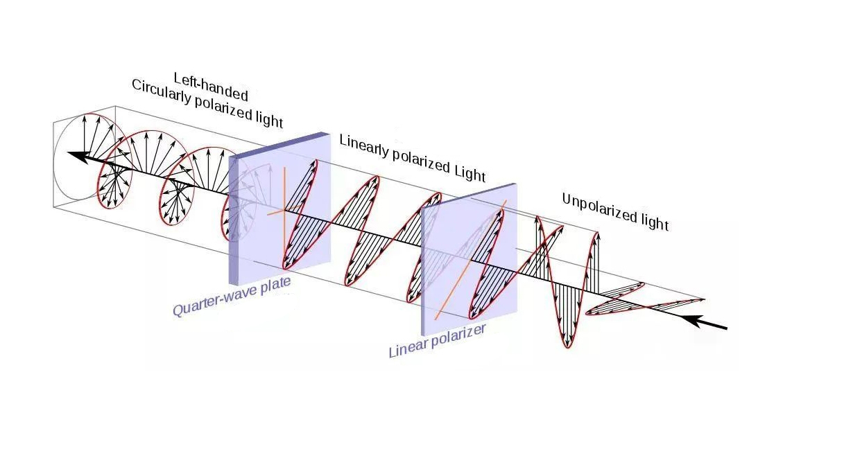
A single criterion converts phase difference into a polarisation state. Let the incident linear polarisation make an angle θ with the fast axis, and let χ be the ellipticity angle of the output:
sin 2χ = sin 2θ · sin Γ
- Γ = 90°, θ = 45°: sin 2χ = 1, so χ = 45° and the output is circular, the textbook use of a quarter-wave plate.
- Γ = 90°, θ = 30°: sin 2χ = 0.866, so χ ≈ 30° and the output is elliptical, with an axis ratio of tan 30° ≈ 0.58.
- Γ = 180°, any θ: sin Γ = 0, so χ = 0 and the output is still linear, rotated by 2θ relative to the input.
The Jones matrix says it more compactly. In the fast/slow basis a waveplate is diagonal, diag(eiΓ/2, e−iΓ/2); rotated into the laboratory frame, the half-wave plate (Γ = 180°) becomes [[cos 2θ, sin 2θ], [sin 2θ, −cos 2θ]], which is a mirror of the polarisation about the fast axis and therefore equivalent to a rotation by 2θ. That 2θ rule is the single most useful property of a waveplate, and Section 5 returns to it.
One last detail that is easy to overlook: each crystal surface reflects about 4% by Fresnel reflection. An uncoated quartz waveplate therefore loses nearly 8% of the power at its two faces, and the reflected light goes back into the beam path to cause trouble. Practical plates are almost always anti-reflection coated, which brings transmission above 99.5%, at the price of a coating that now limits the damage threshold.
3. Key Parameters: The Specifications That Actually Matter
The datasheet of a waveplate is short, but every line maps onto a specific failure mode. The table below lays out nine parameters and what they really mean. The point is not to memorise definitions but to know which one will bite you.
| Parameter | Meaning | What to ask |
|---|---|---|
| Retardance | Phase difference between the two orthogonal components, quoted as λ/4, λ/2 or in nm | Fix the function first, then the number: λ/4 for linear to circular, λ/2 for rotating the polarisation. A nominal λ/4 plate delivers true circular polarisation only at 45° incidence |
| Design wavelength | The wavelength at which the retardance is calibrated, usually matched by the anti-reflection coating | A 1064 plate used at 1030 is roughly 3° off in phase; the higher the order the larger the error, so a different band means a different plate |
| Retardance accuracy | Deviation of the actual retardance from the nominal value, typically λ/100 to λ/500 | λ/300 at 1064 nm is 3.5 nm of path difference, or 1.2° of phase. λ/100 is fine for imaging, but interferometry wants λ/300 or better |
| Wavelength bandwidth | The wavelength span over which retardance stays inside tolerance | A true zero-order plate holds over tens to hundreds of nm, a multi-order plate only over a few nm. Broadband sources such as supercontinuum or multi-wavelength systems need achromatic plates |
| Temperature coefficient | Relative rate at which retardance changes with temperature | Multi-order plates run at about 0.1%/°C, which for a 10th-order λ/4 plate works out at 3–4°/°C. Zero-order scales by 1/order, so anything needing thermal stability must be zero-order |
| Transmission | Single-pass transmission after coating, including surface reflection and absorption | A double-side coated plate usually exceeds 99.5%; uncoated quartz reflects about 4% per face, so one plate costs you nearly 8% |
| Clear aperture and wavefront | Usable aperture, surface figure and material homogeneity | 5–10 mm is the common size. For large apertures ask about surface figure (λ/10) and index homogeneity, or the plate itself will distort your wavefront |
| Damage threshold | Peak power density or pulse energy density the plate can survive | A single-crystal fused-silica true zero-order plate is of order 10 J/cm² (1064 nm, 10 ns); cemented stacks drop to 1–2 J/cm² because of the adhesive; femtosecond work needs bare plates |
| Acceptance angle | How far from normal incidence the retardance stays in tolerance | Zero-order plates tolerate ±5°, multi-order often only ±1°. Tilting changes both the effective thickness and Δn, so a converging beam has to be checked against its marginal ray |
4. Main Types: Zero-Order, Multi-Order, Compound and Achromatic
There is really only one variable behind the classification: how thick a piece of crystal is used to produce the retardance. Thickness sets the order, and the order sets bandwidth, thermal sensitivity and manufacturability. Almost every performance difference follows from it.
| Type | Construction | Bandwidth | Thermal stability | Damage threshold | Typical use |
|---|---|---|---|---|---|
| True zero-order | A single crystal whose thickness is one retardance | Wide, tens to hundreds of nm | Best | Highest, no adhesive | High power, femtosecond, precision metrology |
| Compound zero-order | Two multi-order plates cemented with their optic axes crossed, total retardance is the difference | Fairly wide | Good | Moderate, limited by the cement | General laboratory and industrial beam paths |
| Low-order | Single plate, only a few waves of order | Moderate | Fair | High | Cost-sensitive fixed-wavelength work |
| Multi-order | Single plate, tens to hundreds of waves of order | Narrow, only a few nm | Poor | High | Cheap solution for one wavelength at stable temperature |
| Achromatic | Two birefringent materials combined so that their dispersion cancels | Very wide, up to hundreds of nm | Good | Moderate, limited by cement and stack | Supercontinuum and multi-wavelength systems |
The difference between true and compound zero-order is routinely blurred by sales wording. A true zero-order plate is one crystal whose thickness equals the retardance: best performance, but so thin that large apertures are essentially unobtainable. A compound zero-order is two multi-order plates cemented with their optic axes crossed, so the total retardance equals the difference between them. Thickness comes back into the millimetre range, handling and coating become easy and cost stays under control, at the price of cement that lowers the damage threshold by an order of magnitude and stress that adds a little wavefront distortion. Most affordable plates sold as zero-order are the latter.
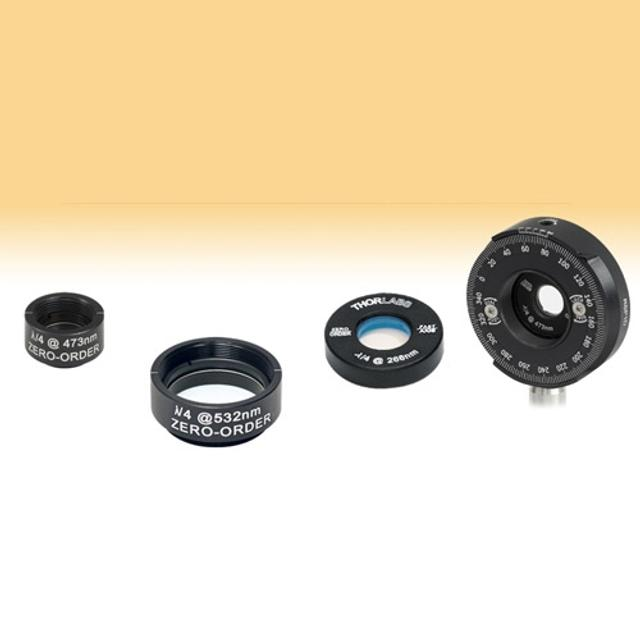
The choice of material is likewise dictated by Δn. The smaller the birefringence, the greater the thickness needed for a given retardance: a disaster for true zero-order, which becomes too thin, and a benefit for multi-order, which can then be made thinner.
| Material | Δn at 1064 nm | Thickness for a true zero-order λ/4 | Notes |
|---|---|---|---|
| Crystal quartz | about 0.0086 | about 31 μm | Most common; wide transmission band and high damage threshold, but a true zero-order plate is unworkably thin |
| Magnesium fluoride | about 0.012 | about 22 μm | Larger birefringence, covers the deep ultraviolet through to the mid-infrared |
| Mica | about 0.006 | about 44 μm | Naturally cleavable into thin sheets and inexpensive, but homogeneity and consistency are only fair |
| Calcite | about 0.17 | about 1.6 μm | The birefringence is so large that a single plate would be unworkably thin, which is why calcite goes into prisms rather than waveplates |
5. Temperature, Fast Axis and Rotation Angle: Three Practical Pitfalls
5.1 Temperature: Why Multi-Order Plates Suffer from Heat
Temperature changes retardance along two paths: thermal expansion changes the thickness d, and the birefringence Δn itself drifts with temperature. The second usually dominates. Taken together, the relative temperature coefficient of a multi-order plate is of order 0.1%/°C.
That number sounds tiny, but it acts on the total retardance. A 10th-order λ/4 plate carries 10.25 waves, about 3690°, so a relative change of 0.1% is a phase drift of 3.7° per degree Celsius. Let the air conditioning fail on a hot afternoon and a 5 °C swing turns a λ/4 plate into a λ/4 plate plus 18°; circular polarisation collapses into an ellipse on the spot. The same 0.1% acting on a true zero-order plate gives only 90° × 0.1% ≈ 0.09°/°C, a factor of 41 better, exactly the ratio of the two orders.
So for thermally demanding work such as precision metrology, research-grade polarimetry or long-exposure polarisation imaging, either specify a true zero-order or achromatic plate, or fit an actively temperature-controlled mount, or simply put the plate where the thermal environment is most stable, away from pump sources and power-absorbing parts.
5.2 Fast Axis and Slow Axis: The Step Most Often Reversed
A waveplate has two orthogonal polarisation axes. The component polarised along the fast axis sees the lower index and travels faster; the component along the slow axis sees the higher index and travels slower. The phase difference they accumulate is the retardance. For a positive uniaxial crystal such as quartz (ne > no) the o-ray direction is the fast axis and the e-ray direction the slow axis; a negative uniaxial crystal such as calcite is the other way round. This has to be looked up per material, never assumed.
The fast axis is usually marked by a scribe line on the edge of the plate or a dot on the mount, but in the lab you want a measurement you can trust: sandwich the plate between two crossed polarisers and rotate it. Transmission then varies periodically with angle. When the plate axis is parallel or perpendicular to the first polariser, the incident polarisation is not split between the two components, the output stays linear and the second polariser blocks it completely, giving a transmission minimum. Those minima mark the axis directions, and a source of known polarisation plus an analyser then tells you which of the two is fast. The method works for both λ/2 and λ/4 plates and is the quickest way to check whether the engraved mark can be believed.
5.3 Rotation Angle and Polarisation State: Using the 2θ Rule
A waveplate’s effect depends not only on its retardance but on the angle between the incident polarisation and the fast axis. That rule is what turns a fixed component into an adjustable tool.
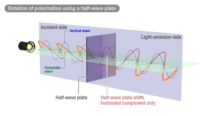
- Half-wave plate: the output stays linear and is rotated by 2θ relative to the input. Fast axis at 22.5° gives polarisation at 45°, fast axis at 45° gives polarisation at 90°. This is the basis of every continuously variable attenuator and every polarisation-rotation scheme.
- Quarter-wave plate: θ = 45° gives circular output; any other θ gives elliptical output with its axes along the fast and slow directions; at θ = 0° or 90° the output stays linear, as if no plate were there. Run it backwards and circular input emerges as linear, with the direction set by the handedness: left- and right-circular give linear outputs 90° apart.
One property must be remembered: a waveplate is a reciprocal device. Light behaves identically from either face, and a beam that passes through and returns comes back in its original state. That is precisely why it cannot replace a Faraday rotator (Myth 6 in Section 7). Combining a λ/4 plate with a mirror is a different matter: the outbound beam becomes circular, reflection flips the handedness, and the return pass converts it back to linear but rotated by 90°, so a polarising beam splitter can dump the return light out of the path. This layout is very common in interferometers and in fibre return-light isolation.
6. Applications: What a Waveplate Does Inside a System
The applications look scattered, but they all reduce to three actions: turning linear into circular or back again, rotating the polarisation to a required angle, and modulating the polarisation periodically. Everything below is a combination of those three.
- Optical isolators: the Faraday rotator provides the non-reciprocal 45° rotation, with a λ/2 plate on each side for angle matching, so that forward light passes and backward light is rejected by a polariser. The waveplate does not isolate anything here; it only squares the polarisation up with the axis.
- Continuously variable attenuators: a λ/2 plate followed by a polarising beam splitter. Rotating the plate changes the angle between the polarisation and the transmission axis, so transmitted power follows cos² continuously. The mechanics are simple, there is no wavelength dependence, and it suits precision power setting far better than a neutral density filter.
- Circularly polarised laser processing: a λ/4 plate converts linear to circular, removing the material’s sensitivity to direction during cutting and drilling and visibly reducing wall taper and directional burr. On highly reflective and brittle materials this single step is often the difference in quality.
- Interferometry and return-light isolation: a λ/4 plate plus a mirror in double pass rotates the returning polarisation by 90°, after which a polarising beam splitter steers it away and protects the seed source and fibre. It is one of the most common layouts in ultrafast amplifiers.
- Polarimetry and ellipsometry: the rotating-waveplate method uses a continuously rotating λ/4 or λ/2 plate to modulate the polarisation state, while a fixed analyser and detector read out the Fourier components from which the sample response is recovered. Compared with a rotating analyser it also delivers the phase information.
- Coherent communications and fibre sensing: polarisation multiplexing has to place two signals on orthogonal polarisations, and the receiver has to demodulate and track them; the waveplate is the reference element that puts the state into a known frame. Fibre current sensors use a λ/4 plate directly to convert linear into circular and improve linearity.
- Ultrafast laser systems: stretchers, compressors and regenerative amplifiers are sensitive to polarisation, and λ/4 and λ/2 plates control it at the entrance and exit of each stage. Such systems demand single-crystal fused-silica true zero-order plates, because a cemented stack fails first at the adhesive under femtosecond peak power.
7. Common Myths: Six Widespread Misunderstandings
Waveplates have few parameters but plenty of misconceptions, most of them descended from the vague impression that a waveplate changes the light.
Myth 1: A waveplate changes the intensity of light
An ideal waveplate only rearranges phase: both components pass and total power is unchanged. If the beam looks weaker after you drop a plate in, there is a polariser further downstream, and that is the component doing the subtraction. Real losses come entirely from coating reflection and material absorption, typically under 1%.
Myth 2: One λ/4 plate works at any wavelength
Retardance is inversely proportional to wavelength, and Δn varies with wavelength as well. A λ/4 plate made for 1064 nm becomes roughly 90° × 1064 / 808 ≈ 118° at 808 nm, no longer a quarter wave by any measure. Either order the plate for the band you actually use, or move to an achromatic design.
Myth 3: A zero-order plate is just a very thin plate
A true zero-order plate is indeed only tens of micrometres thick, but most zero-order plates on the market are compound stacks of two multi-order plates cemented with crossed axes, and their thickness is in the millimetre range. The quickest way to tell is to ask about construction and damage threshold: a cemented stack is limited to the 1–2 J/cm² range by its adhesive.
Myth 4: A multi-order plate can be used at any temperature and wavelength
It cannot. A multi-order plate has a bandwidth of a few nm and a temperature coefficient of order 0.1%/°C, so a few degrees of drift or a few nanometres of wavelength shift move the retardance well away from its design value. It suits single-wavelength, thermally stable setups only; anything sensitive to temperature or wavelength needs zero-order or achromatic.
Myth 5: Any rotation angle gives circular polarisation
Only when the incident linear polarisation sits exactly 45° from the fast axis of a λ/4 plate is the output truly circular. Away from 45° the output is elliptical, with ellipticity following sin 2χ = sin 2θ · sin Γ; at 0° or 90° the output is linear again and the plate does nothing.
Myth 6: A half-wave plate can serve as an optical isolator
It cannot. A half-wave plate is reciprocal: light reflected back through it is rotated straight back to where it started and passes the upstream polariser as before. Isolation depends on the non-reciprocity of a Faraday rotator. A λ/4 plate plus a mirror only stops light returning from that mirror; it cannot stop reflections from a workpiece or a lens surface.
Leave a Reply