


What Is a Polarizer? How to Filter and Control the Polarisation of Light
A polarizer does one thing: it chooses between two orthogonal polarisation directions, letting one through and blocking or diverting the other. It sounds like a sieve, but its weight in a laser system goes far beyond cutting glare. An isolator only works because of it, an interferometer trims its contrast with it, and coherent communication splits polarisation with it. Four things decide whether a part will work: is the extinction ratio high enough (10³:1 and 10⁶:1 are three orders of magnitude apart), how much power does the insertion loss eat, will the damage threshold survive your peak power density, and can the acceptance angle tolerate your beam divergence. This article starts from absorption, birefringence, thin-film interference and wire grids, then works through extinction ratio, degree of polarisation and the choice between Glan prisms, before closing on types, applications and misconceptions.
Contents
- 1. The Core Concept: What Is a Polarizer
- 2. How It Works: Four Ways of Making Light Take Sides
- 3. Key Parameters: Reading a Polarizer Specification
- 4. In Depth: Extinction Ratio, Glan Prisms, Waveplates and DOP
- 5. Main Types: The Polarizer Family
- 6. Applications: Where Polarizers Are Used
- 7. Common Misconceptions: Six Widely Held Myths
1. The Core Concept: What Is a Polarizer
A polarizer is a component that transmits one polarisation state selectively: light vibrating along a particular direction passes, while light polarised orthogonally is absorbed, reflected or diverted out of the beam. That direction is the transmission axis. Frequency is unchanged and, ideally, so is phase; the device only subtracts. A polarizer is therefore a directional attenuator rather than a polarisation converter. Turning linear into circular polarisation is the job of a waveplate.
Stack two polarizers and the behaviour is obvious: brightest with the axes parallel, darkest when crossed, and at an intermediate angle θ the transmitted intensity follows Malus’s law, I = I₀·cos²θ. That is also the most common use of a polarizer: continuous attenuation without touching anything else about the beam.
By purpose they fall into two groups. One outputs a single beam, with the rejected polarisation absorbed or diverted, and the other keeps both, which is a polarising beam splitter. The first is simple and cheap, the second wastes no energy, and the choice comes down to whether you can afford to throw half the power away.
2. How It Works: Four Ways of Making Light Take Sides
2.1 Absorptive: swallowing the unwanted direction
The most familiar kind. A polymer film is stretched so that its long molecular chains align, light vibrating along the chains is strongly absorbed, and light perpendicular to them passes almost untouched. Dichroic glass, polarising sunglasses and the film in an LCD all belong here. The part is cheap, thin and available in large apertures, and the price is that the rejected half of the power becomes heat, so at anything above low power the film warms, fades and eventually burns through.
2.2 Birefringent total internal reflection: sending the unwanted direction away
In a birefringent crystal such as calcite, α-BBO or YVO₄, the ordinary and extraordinary rays see different refractive indices. Cut the crystal into a prism at a particular angle and the ordinary ray strikes the internal face beyond the critical angle, is totally internally reflected and is absorbed by the side wall, while the extraordinary ray passes straight through. The output is linear polarisation of very high purity. Glan-Taylor, Glan-Foucault and Glan-Thompson all belong to this family and differ in cutting angle and in whether a cement layer is present.
2.3 Thin-film interference: reflect s, transmit p
When a multilayer dielectric stack works at the Brewster angle, p-polarised light sees almost zero reflection at every interface while s-polarised light is reflected and added up layer by layer. Dozens of such layers on a plate or on the hypotenuse of a cube give a thin-film polarizer. Its extinction ratio is below that of a crystal prism, but the aperture can be large and the damage threshold high, with ion-beam-sputtered coatings taking more than ten J/cm², which is why it is the usual choice inside high-power Nd:YAG lasers.
2.4 Wire grid: a sub-wavelength metal grating
A fine metal grating, typically tungsten, is laid down with a period far shorter than the wavelength. The field component parallel to the wires drives the electrons and is reflected; the perpendicular component is transmitted. Because the period must be much shorter than the wavelength, wire-grid polarizers serve the infrared and terahertz bands and are hard to make for visible light. Their advantage is large aperture, broad bandwidth and high power handling, since they absorb very little.
3. Key Parameters: Reading a Polarizer Specification
A polarizer datasheet runs to only a few lines, yet any one of them can decide whether a system works. When you read ‘high extinction ratio’, first check the wavelength and the angle it was measured at.
| Parameter | What it means | Why it matters |
|---|---|---|
| Extinction ratio | Ratio of transmission with the polarisation parallel and perpendicular to the transmission axis, ER = Tmax / Tmin | Sets polarisation purity. 10³:1 is enough for general polarising, while isolators and high-contrast interferometry need 10⁵:1 or better; in decibels, 10³:1 is 30 dB and 10⁶:1 is 60 dB. |
| Insertion loss | Power lost by polarisation aligned with the transmission axis, including reflection, absorption and scatter | Absorptive film transmits only 38–42%, crystal prisms 80–90%, and thin-film types better than 95%. Cascaded in several stages, this figure decides how much power the system has left. |
| Operating wavelength range | The spectral band over which extinction ratio and transmission hold their specification | Calcite covers about 350 nm to 2.3 μm, α-BBO reaches into the ultraviolet, thin-film types are designed for one laser wavelength, and wire grids serve the infrared and terahertz region. In the deep ultraviolet usually only α-BBO and wire grids are available. |
| Acceptance angle (field of view) | The range of incidence angles over which the extinction ratio does not fall significantly | Crystal prisms accept only a few degrees and thin-film types even less, since they are designed at the Brewster angle. With a divergent or scanned beam, too narrow an acceptance angle collapses the extinction ratio. |
| Laser-induced damage threshold (LIDT) | Continuous power or pulse energy density the part can take per unit area | An air-spaced crystal prism sits far above absorptive film and cemented parts, and thin-film types sit in between, towards the top. Pick the wrong type for high power and the optic blisters within seconds. |
| Wavefront distortion | Disturbance of the transmitted wavefront, quoted as λ/4, λ/8 and so on | Prisms are thick and carry internal stress, so their wavefront is usually worse than that of a thin-film part. Interferometry and imaging have to budget for this. |
| Clear aperture and construction | Usable diameter, and whether the part is a film, a prism or a plate | Large apertures are only possible with film and wire-grid types; prisms are limited by crystal size, typically 10–25 mm. Also watch the mark that shows the transmission axis: mount it 90° out and nothing gets through. |
4. In Depth: Extinction Ratio, Glan Prisms, Waveplates and DOP
4.1 Extinction ratio: one number, three traps
The extinction ratio is ER = Tmax / Tmin, where Tmax is the transmission with polarisation parallel to the axis and Tmin with polarisation perpendicular. It looks straightforward and hides three traps. First, it is measured at a particular wavelength, and one order of magnitude can separate two wavelengths. Second, it degrades quickly with angle and means nothing outside the acceptance angle. Third, it says nothing about the intensity at which it was measured: an absorptive film heats up at high power and its extinction ratio drops.
In practice it is more useful in decibels: ER(dB) = 10·log₁₀(ER). 10³:1 is 30 dB, 10⁴:1 is 40 dB and 10⁶:1 is 60 dB. The isolation of an isolator is roughly the combination of the polarizer extinction ratio and the quality of the Faraday rotator, so a 30 dB film cannot build a 40 dB isolator.
| Type | Typical extinction ratio | Typical transmission | Notes |
|---|---|---|---|
| Glan-Taylor prism | 10⁵:1 – 10⁶:1 | about 80–90% | Highest extinction ratio, air-spaced with no cement, handles high power |
| Glan-Foucault prism | 10⁴:1 – 10⁵:1 | about 70–80% | Also air-spaced, but shorter, with a smaller acceptance angle |
| Thin-film polarizer | 10³:1 – 10⁴:1 | 95% or more | Dielectric interference coating: large aperture, high threshold, angle-sensitive |
| Wire-grid polarizer | of order 10³:1 | about 70–80% | Broadband, suits infrared and terahertz, available in large apertures |
| Absorptive polarizing film | 10²:1 – 10³:1 | about 38–42% | Cheapest option, used in displays and photography; very low threshold |
4.2 The three Glan prisms: Taylor, Foucault and Thompson
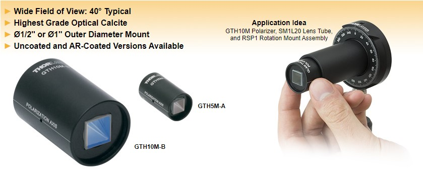
- Glan-Taylor: two calcite prisms with an air gap between them, separating the beams by total internal reflection of the ordinary ray at the diagonal. Extinction ratio 10⁵–10⁶:1, a relatively generous acceptance angle, and no cement, hence a high threshold: the first choice for high power and high precision, at the cost of price and limited crystal size.
- Glan-Foucault: air-spaced as well, but a different cutting angle makes the prism shorter and the acceptance angle smaller. Extinction ratio 10⁴–10⁵:1, simple to build and cheaper, suited to well-collimated beams that do not need a wide acceptance angle.
- Glan-Thompson: the two prisms are cemented, traditionally with Canada balsam. The body is longer and the extinction ratio is respectable, but the cement absorbs light and tolerates heat poorly, yellowing and blistering at high power. It now serves mainly low-power measurement, and air-spaced designs have taken over the high-power role.
Calcite has one fatal weakness: it dislikes moisture, heat and mechanical shock. It cleaves easily along its cleavage planes, and a damp surface loses transmission, so crystal prisms are almost always sealed in a metal housing with apertures at each end. Calcite also absorbs strongly in the ultraviolet, where α-BBO takes over; for high-power near-infrared work YVO₄ is an option, harder and better conducting than calcite, with a smaller birefringence and a somewhat lower extinction ratio.
4.3 Polarizer and waveplate: one subtracts, the other transforms
| Property | Polarizer | Waveplate |
|---|---|---|
| Core function | Selects a polarisation direction, passing only the component along the transmission axis | Changes the polarisation state, turning one form into another |
| Intensity | Always attenuated; unpolarised input loses at least half its power | Ideally unchanged, since only the phase is modified |
| Output state | Always linear polarisation | Linear, circular or elliptical polarisation |
| Typical use | Purifying polarisation, analysis, continuous intensity control | Rotating the polarisation direction, converting between linear and circular |
A useful picture: a polarizer is a sieve that passes only the correctly oriented part and throws the rest away, so the beam always weakens. A waveplate is a gearbox: everything gets through, only the phase difference between the two components is altered. The two are often paired, with a half-wave plate rotating the polarisation and a polarizer analysing it, which makes a variable attenuator.
4.4 Degree of polarisation: how pure the light itself is
Real light is rarely 100% linearly polarised; most of it is partially polarised. The degree of polarisation (DOP) is (Imax − Imin) / (Imax + Imin), where Imax and Imin are the maximum and minimum transmitted intensities seen while rotating a polarizer. Unpolarised light has DOP = 0, fully linearly polarised light has DOP = 1, and partial polarisation falls in between. The number describes the light, not the device, so measuring it needs a polarizer with a high enough extinction ratio; otherwise the result mixes device and light together.
5. Main Types: The Polarizer Family
Classification runs along two axes: the mechanism that rejects the unwanted polarisation (absorption, total internal reflection, interference, grating), and whether one beam or both are kept.
| Type | Mechanism | Characteristics | Typical use |
|---|---|---|---|
| Absorptive polarizing film | Directional absorption by stretched polymer chains | Cheap, thin, large aperture; low transmission and a very low threshold | Displays, photography, teaching, low-power analysis |
| Crystal prism polarizer | Birefringence plus total internal reflection, diverting and absorbing the ordinary ray | Highest extinction ratio and high threshold; small aperture, expensive, moisture-sensitive | Isolators, high-contrast interferometry, precision polarimetry |
| Thin-film polarizer (plate) | Multilayer dielectric stack separating s and p at the Brewster angle | Large aperture, high threshold, high transmission; angle-sensitive | Intra-cavity polarising in solid-state lasers such as Nd:YAG |
| Polarising beam splitter cube (PBS) | Diagonal coating transmits p and reflects s | Both outputs usable, so energy is conserved; the cement layer limits the threshold | Polarisation combining, polarisation-diversity reception, optical switches |
| Wire-grid polarizer | Sub-wavelength metal grating reflecting the component parallel to the wires | Broadband, large aperture, little absorption; only for long wavelengths | Infrared imaging, terahertz, millimetre waves |
| Brewster window or plate | Placed at the Brewster angle, so p-polarised light passes without reflection loss | Extremely low loss and very high threshold; passes p only, with no extinction ratio to quote | Intra-cavity polarising, gas laser windows |
6. Applications: Where Polarizers Are Used
- Polarising and cleaning up a laser: a Brewster plate inside the cavity or a thin-film polarizer outside it gives a stable linear output, and an external polarizer raises the purity for subsequent frequency conversion, modulation or isolation.
- Optical isolators: polarizer, Faraday rotator and polarizer again, letting forward light through and blocking the return. The isolation is limited by the extinction ratio of the two polarizers.
- Continuous attenuation: a half-wave plate followed by a polarizer, where rotating the waveplate changes the transmission. This is cleaner than rotating the polarizer itself, because the beam direction stays put.
- Interferometry and ellipsometry: a rotating analyser with a detector reads out the change in polarisation state, the core of an ellipsometer or a polarisation interferometer.
- Coherent optical communication: polarisation-diversity reception separates and demodulates the two polarisation components, and the extinction ratio of the PBS feeds straight into the bit error rate.
- Displays and imaging: an LCD sandwiches liquid crystal between two polarizing films to control brightness, while a polarisation camera captures four directions at once for glare removal and material identification.
- Everyday optics: polarising sunglasses reject the horizontally polarised glare from water and road surfaces, and 3D cinema separates the two eye views with orthogonal polarisation.
7. Common Misconceptions: Six Widely Held Myths
A polarizer has few specifications, yet misconceptions cluster around them, mostly from over-extending the sieve analogy.
Misconception 1: A polarizer turns any light into linear polarisation without losing energy
It selects, it does not convert. Unpolarised light passing an ideal polarizer necessarily keeps only half its power, with the other half absorbed or diverted. Converting unpolarised light to linear polarisation without loss is physically impossible, unless a polarising beam splitter puts the rejected beam to work as well.
Misconception 2: The higher the extinction ratio, the better
A higher extinction ratio usually means a narrower band, a tighter angular range, a smaller aperture and a higher price. Imaging and illumination are well served by 10³:1; only isolators and high-contrast interferometry need 10⁵:1 or more.
Misconception 3: All polarizers are absorptive
Absorptive film is only one kind. Crystal prisms divert the unwanted polarisation out of the beam by total internal reflection, thin-film types reflect it away by interference, and wire grids reflect it off the wires. The last three do not rely on absorption, which is why they take far more power.
Misconception 4: A polarizer can extinguish light completely
It cannot. The best Glan-Taylor prism reaches about 10⁶:1, so one part in a million of the crossed component still leaks through, and thin-film types are typically only of order 10³:1. Two crossed polarizers look completely dark simply because the eye and the detector do not have the dynamic range to see the leak.
Misconception 5: Every polarizer suits high-power lasers
They do not all suit it. Absorptive film turns the rejected light into heat and will fade, distort or burn through at modest power, and a cemented Glan-Thompson fails when its cement gives way. High power calls for an air-spaced crystal prism or a thin-film polarizer, sized against the peak power density.
Misconception 6: A polarizer and a waveplate are much the same
They are entirely different. A polarizer subtracts: one component is rejected and the intensity must fall. A waveplate transforms: both components survive and only their phase difference changes. One changes intensity, the other changes state, and confusing them derails the whole optical design.
Leave a Reply