


What Is a Beam Splitter? How One Beam Becomes Two
A beam splitter performs the one act optics rarely asks for: it distributes. One beam becomes two, by intensity, by wavelength or by polarisation, and both outputs stay usable. There are no moving parts, yet the component decides whether an interferometer works, whether a power monitor tells the truth, and whether a fluorescence microscope can separate excitation from emission. Four things govern the choice: how far the splitting ratio drifts at your actual wavelength and angle, how much polarisation-dependent loss a non-polarising part still carries, whether the lateral shift and astigmatism of a plate are acceptable, and whether the cement layer will fail first at high power. This article starts from partial reflection and thin-film interference, gives the magnitudes for ratio, PDL and extinction ratio, then compares cube with plate and PBS with NPBS, before closing on types, applications and misconceptions.
Contents
- 1. The Core Concept: What Is a Beam Splitter?
- 2. How It Works: How One Beam Is Split
- 3. Key Parameters: Reading a Beam Splitter Specification
- 4. Selection Points: Ratio, PDL, Cube versus Plate
- 5. Main Types: The Beam Splitter Family
- 6. Applications: Where Beam Splitters Are Used
- 7. Common Misconceptions: Six Widely Held Myths
1. The Core Concept: What Is a Beam Splitter?
A beam splitter is an optical component that divides one incident beam into two or more, either by intensity ratio or by wavelength or polarisation state. The task looks simple; the difficulty is that every output has to stay clean. Energy must not vanish, the wavefront must not degrade noticeably, and the polarisation must not be altered behind your back. Run backwards, the same part is a beam combiner, and that is what separates it from a polariser or a filter: those discard, a splitter distributes.
The construction always has three parts: substrate, splitting coating and antireflection coating on the transmitting faces. N-BK7 or fused silica is the usual substrate, the first cheap and homogeneous, the second able to take high power and ultraviolet. The splitting coating sets the ratio and the polarisation behaviour, and may be metallic (broadband but absorbing), dielectric (low loss but narrow-band and angle-sensitive) or a multilayer polarising stack. The antireflection coating suppresses unwanted interface reflections, which means fewer ghosts and less return loss.
2. How It Works: How One Beam Is Split
2.1 Partial reflection: the most direct way to split
Coat a glass surface with a partially reflecting layer. Part of the incident light is reflected, part is transmitted, and the beam is divided. Plate and cube splitters both work this way and differ only in geometry: a plate is a coated parallel flat, a cube is two right-angle prisms cemented together with the coating on the hypotenuse. The ratio comes from the reflectance of the coating, so a 50:50 part is simply a coating designed for R = T = 50%.
2.2 Polarisation splitting at oblique incidence: the root of both PDL and PBS
At an oblique interface, p-polarised light, with its electric field in the plane of incidence, and s-polarised light, with the field perpendicular to it, do not reflect equally. This is a direct consequence of the Fresnel equations, and at 45° the two reflectances of a single coating can differ by a dozen percentage points. Two things follow. A non-polarising splitter can never be entirely polarisation-independent, so some PDL always remains. And if that difference is pushed to its limit, with p transmitted completely and s reflected completely, the result is a polarising beam splitter.
2.3 Polarising splitting: p passes, s reflects
The hypotenuse of a polarising beam splitter cube carries dozens of alternating high- and low-index layers, designed so that the internal angle satisfies the Brewster condition. p-polarised light then passes through every interface almost without reflection, while s-polarised light is reflected at each layer, adds up and is turned through 90°. The two outputs therefore carry mutually perpendicular linear polarisations. How cleanly the separation is done is described by the extinction ratio: Tp over Ts in the transmitted arm, or Rs over Rp in the reflected arm.
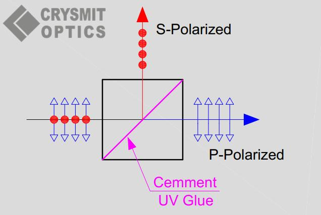
2.4 Dichroic splitting: by wavelength, not by intensity
A dichroic splitter is essentially a long-pass or short-pass filter used at 45°: short wavelengths reflect, long wavelengths pass, or the other way round. It ignores polarisation and ignores ratio; only wavelength counts. Separating excitation from emission in a fluorescence microscope, or pump at 1064 nm from signal at 532 nm in a laser system, is its job. The width of the transition band around the design wavelength sets the crosstalk between the two channels.
2.5 Fibre splitters: coupling through the evanescent field
Strip the cladding from two fibres, lay them side by side and fuse and taper them. Once the cores are close enough their evanescent fields overlap and power transfers back and forth between them. The coupling is set by the length of the tapered region, which is how 50:50, 90:10 and even 1:99 ratios are made. This fused biconical taper (FBT) approach has no free-space path, so insertion loss is low and the part is mechanically stable, which makes it the standard splitter in fibre communications. Planar lightwave circuit (PLC) splitters instead define the branching lithographically, giving better uniformity for high port counts in 1×N configurations.
3. Key Parameters: Reading a Beam Splitter Specification
A splitter datasheet is shorter than a lens datasheet, but every line maps onto a use case. When you see ’50:50′, resist ordering until you have turned the page and read the tolerance and the wavelength.
| Parameter | What it means | Why it matters |
|---|---|---|
| Splitting ratio R:T | Ratio of reflected to transmitted power, such as 50:50, 70:30 or 90:10 | Choose it from the job: sampling and monitoring take 99:1 or 99.5:0.5, while an interferometer takes 50:50 so both arms carry similar power. Standard parts hold about ±5% and precision parts ±1–2%, so the nominal figure is not the measured one. |
| Operating wavelength range | The band over which the ratio stays within specification | A dielectric splitter falls off a cliff outside its design band rather than decaying gently. Multi-wavelength systems need broadband or dual-band designs, and ultrafast work also has to consider coating dispersion. |
| Angle of incidence | The angle the coating was designed for: 0° for most cubes, 45° for most plates | One or two degrees off moves both the ratio and the phase. A plate must sit at 45°; mount it at 44° and the reflected arm tilts while the transmitted arm picks up extra astigmatism. |
| Insertion loss | The shortfall between the sum of the two output powers and the input power | Free-space parts run 2–5% typically and precision parts stay under 1%; fibre parts are quoted in dB, with fused tapers around 0.05–0.2 dB. Losses add up when parts are cascaded, so do not ignore them. |
| Polarisation-dependent loss (PDL) | The largest difference in insertion loss between input polarisation states | Relevant even for non-polarising parts: good ones sit near 1%, ordinary ones reach 5%. In polarisation-sensitive systems such as coherent detection or fibre sensing, PDL turns straight into measurement error. |
| Extinction ratio | Polarisation purity of the two outputs, written as Tp/Ts or Rs/Rp | Cube PBS parts commonly reach 1000:1 and high-end ones 10000:1, while plate PBS parts are one or two orders of magnitude lower. Too little extinction ratio and both isolation and interference contrast suffer. |
| Transmitted wavefront distortion | Wavefront error in transmission, quoted as λ/4, λ/8 and so on | Set jointly by substrate figure and coating stress. Interferometry and imaging need λ/10 or better, and heating of the coating at high power makes the figure worse. |
| Laser-induced damage threshold (LIDT) | Continuous power or pulse energy density the part can take per unit area | A cemented cube is limited by its cement layer and sits far below a plate; high power demands a cement-free construction. For pulses the mechanism also depends on duration. |
| Construction and material | Cube, plate, pellicle or fibre; BK7 or fused silica substrate | A cube saves space and has no beam shift; a plate is cheaper and takes more power but shifts the beam; a pellicle is thin enough to be almost ghost-free yet vulnerable to air currents and touch. Ultrafast systems also have to count the material dispersion of the substrate. |
4. Selection Points: Ratio, PDL, Cube versus Plate
4.1 Splitting ratio: decide how much light each arm needs
The splitting ratio is the reflected-to-transmitted power ratio. 50:50 is the general case, used in interferometers and Mach-Zehnder layouts where both arms should carry similar power for high contrast. 70:30 or 80:20 suits cases where one arm needs more energy. Power monitoring uses 99:1 or even 99.5:0.5, taking just enough light for a detector. A polarising splitter does not divide by power at all: its two outputs depend on the input polarisation, and the quoted 50:50 only holds for 45° linear or circular input.
Two things are easily missed. First, the ratio is defined at a particular wavelength and angle, and shifts if either changes, so broadband use needs the whole curve rather than a single point. Second, the two arms do not have equal wavefront quality: the reflected arm touches the coating once, while the transmitted arm crosses the entire substrate, so in a wavefront-critical system let the important arm take the reflection.
4.2 PDL and extinction ratio: two figures that get confused
Polarisation-dependent loss describes how much the loss of one device changes as the input polarisation is rotated; it measures the imperfection of a non-polarising splitter. The extinction ratio describes the ratio of the two polarisation components in one output; it measures the separation capability of a polarising splitter. Smaller is better for the first, larger for the second, and neither substitutes for the other.
Zero PDL is the ideal for a non-polarising splitter and it is unattainable. In a cube the light meets the coating at normal incidence, so the s–p difference is squeezed almost flat and PDL is usually better than in a plate. A plate works at 45°, where the Fresnel difference shows directly, so its PDL is naturally larger. Polarisation-sensitive systems, such as coherent receivers, fibre gyroscopes and polarimetry, should therefore take a cube NPBS rather than a cheaper plate.
4.3 Cube versus plate: not a ranking, but different prices to pay
| Property | Cube beam splitter | Plate beam splitter |
|---|---|---|
| Construction | Two right-angle prisms cemented, coating on the hypotenuse | One parallel flat, coating on one face |
| Beam path | No lateral shift in transmission; reflection turned through 90° | Transmitted beam is displaced laterally: about 1.6 mm for a 5 mm BK7 plate at 45° |
| Astigmatism and wavefront | Normal incidence, so essentially no astigmatism introduced | Tilting at 45° introduces astigmatism into the transmitted beam, worse at faster f-numbers |
| PDL | Low, because the light strikes the coating at normal incidence | Higher, because the s–p difference is clear at oblique incidence |
| Damage threshold | Low, limited by the cement layer | High: no cement, a single substrate |
| Ghost images | Few; the outer faces can be antireflection coated | Several; reflection from the rear face produces a displaced ghost, which a wedge plate can steer out of the beam path |
| Material dispersion | Light travels through glass: a 10 mm BK7 cube contributes about 360 fs² near 800 nm | Thin substrate, little dispersion; usually preferred for ultrafast work |
| Cost and alignment | Higher; the 90° geometry is built in, so setup is easy | Lower; you must hold 45° and compensate the shift yourself |
| Typical use | Imaging, interferometers, low-power lasers, compact layouts | High-power lasers, broadband splitting, ultrafast systems |
4.4 Two hidden costs of a plate: shift and astigmatism
The transmitted beam of a plate splitter is displaced by roughly d = t·sin(θi − θt)/cos(θt), where t is the thickness, θi the angle of incidence and θt the internal angle. A 5 mm BK7 plate at 45° shifts the beam by about 1.6 mm; if the next element is a small lens or a fibre, that is more than enough to miss. More insidious is astigmatism: a tilted parallel plate acts on the transmitted beam like a cylindrical element, separating the tangential and sagittal foci and stretching the spot into an ellipse. The faster the f-number, the stronger the effect.
There are two ways out: tilt a second plate of the same material in the opposite direction to compensate, or use a cube instead. That is why high-numerical-aperture imaging paths pay the extra for a cube.
4.5 Why a cemented cube fails at high power
Three routes to high-power splitting: ① a cement-free plate splitter, relying on the substrate threshold alone, at the cost of beam shift and astigmatism; ② an air-spaced polarising prism, with a layer of air between two prisms and no organic material in the beam path at all; ③ a wedge plate, which steers the rear-surface ghost out of the beam. A cemented cube, by contrast, almost always fails under kilowatt continuous light or high pulse energy: the cement absorbs, yellows, blisters and finally lets go entirely.
4.6 PBS versus NPBS: do not mix them up

- Polarising beam splitter (PBS): splits by polarisation state. p passes, s reflects, and both outputs are linearly polarised. Extinction ratio is typically 1000:1 and up to 10000:1 in high-end parts. Used wherever polarisation must be separated or combined: isolators, interferometers, polarisation multiplexing, optical switches.
- Non-polarising beam splitter (NPBS): splits by power, ideally without changing or selecting polarisation. Real PDL is not zero, around 1% in good parts. Used where only intensity matters: power sampling, imaging, illumination.
Use a PBS as an NPBS and the ratio drifts with input polarisation, so rotating the input swaps the two output powers. Use an NPBS as a PBS and the extinction ratio is nowhere near enough, so isolation cannot be achieved. This is the easiest purchasing mistake to make, because the two parts can look identical.
5. Main Types: The Beam Splitter Family
Classification runs along three axes: construction (plate, cube, pellicle, fibre), the basis of splitting (intensity, polarisation, wavelength), and whether the ratio can be varied.
| Type | Construction and principle | Characteristics | Typical use |
|---|---|---|---|
| Plate splitter | Parallel flat with a partially reflecting coating on one face | Cheap, high threshold; brings beam shift, astigmatism and ghosts | High-power splitting, broadband monitoring, teaching layouts |
| Cube splitter | Two right-angle prisms cemented, coating on the hypotenuse | No shift, easy alignment; cement limits the threshold, and the glass adds dispersion | Imaging systems, interferometers, compact layouts |
| Pellicle splitter | A few micrometres of nitrocellulose or polyester film, coated | Very thin, almost no shift or ghost; sensitive to air currents, easily damaged | Microscopy, ultraviolet paths, dispersion-critical setups |
| Polarising cube (PBS) | Hypotenuse stack satisfying the Brewster condition | p passes, s reflects; extinction ratio of order 1000:1 | Isolators, polarisation multiplexing, interferometry |
| Air-spaced polarising prism | Two prisms separated by an air gap, no cement | High threshold, no cement ageing; complicated to build and align | High-power polarising splitting, high-energy laser systems |
| Dichroic splitter | Long-pass or short-pass stack, usually designed for 45° | Splits by wavelength with a finite transition band; shifts with s and p | Fluorescence microscopy, laser combining, harmonic separation |
| Fibre splitter | Fused tapered coupling, or a planar waveguide branch | Low insertion loss, mechanically stable, ratios down to 1:99 | Optical communications, fibre sensing, power distribution in fibre lasers |
| Variable splitter | Rotating half-wave plate ahead of a PBS, or a continuously variable attenuator | Ratio continuously adjustable, but needs polarisation control to go with it | Power adjustment, laboratory beam-line tuning |
6. Applications: Where Beam Splitters Are Used
- Interferometers: splitting light into reference and measurement arms and recombining them to form fringes. The wavefront quality of the splitter sets the fringe contrast, and any beam shift moves the optical path difference away from its design value.
- Laser power monitoring: dropping a 99:1 splitter into the path and sending 1% to a photodiode for real-time power. The sampling ratio has to be stable, or the reading drifts with polarisation.
- Beam combining: the same part run backwards, merging several lasers or several wavelengths into one path. Polarisation combining uses a PBS, wavelength combining uses a dichroic, and the two are often cascaded.
- Fluorescence microscopy: a dichroic reflects excitation onto the sample and passes the emission, making it the heart of fluorescence imaging; the width of the transition band sets channel crosstalk.
- Optical communications and fibre networks: fibre splitters distribute power, feed wavelength-division multiplexers and provide OTDR test ports.
- Polarimetry and isolation: a PBS with waveplates forms isolators and polarisation analysers; the higher the extinction ratio, the better the isolation.
- Ultrafast lasers: pellicle or thin-plate splitters sample and divide pulses without the material dispersion of a thick substrate stretching them.
7. Common Misconceptions: Six Widely Held Myths
A splitter has few specifications, which makes it feel obvious at a glance, and that is where the misconceptions collect.
Misconception 1: 50:50 means exactly half and half
Standard parts carry tolerances, with ±5% common and ±1–2% reserved for precision ones. The ratio also moves with wavelength, angle and polarisation, so the nominal figure only holds at the design point. Before using one for a precise power-ratio measurement, measure it.
Misconception 2: A beam splitter can only split, never combine
A splitter is a reciprocal device: run backwards, it combines. Two conditions apply, though. The beams must be mutually coherent, or at least at the same wavelength, and their polarisations must match. When combining with a PBS the two inputs must be orthogonally polarised, otherwise they will not combine and will simply lose power to each other.
Misconception 3: A cube is always better than a plate
A cube saves space, avoids beam shift and has low PDL, but its cement layer caps the damage threshold and its thick substrate adds several hundred fs² of dispersion to an ultrafast pulse. For high power and for ultrafast work a plate is the better part.
Misconception 4: An NPBS is completely polarisation-independent
‘Non-polarising’ means the polarisation dependence is small, not that it is absent. Even the best NPBS retains some PDL at oblique incidence, and a plate shows it most. Polarisation-sensitive systems should specify a cube NPBS and check the PDL figure, rather than trusting the words ‘non-polarising’.
Misconception 5: The splitting ratio holds across the whole spectrum
The ratio of a dielectric splitter comes from an interference design, so it collapses outside the design band, and at some wavelengths it even inverts, with what was reflected now transmitted. Multi-wavelength systems need the whole curve, not the value at the centre wavelength.
Misconception 6: Once installed, the angle no longer matters
A plate must sit at exactly 45°; a degree or two off changes the ratio and tilts the reflected arm. A cube is more forgiving, but rotating it rotates the output polarisation, and in a polarisation system that angle is itself a parameter.
Leave a Reply