



Description
Economical Laser Autofocus Component (Side-Axis Mounting)
Step on the pedal, the machine finds the focus automatically and starts marking — focusing and marking in a single pedal press. This component uses a side-axis mounted laser distance sensor: the sensor is fitted beside the f-theta lens or next to the galvo scanner and measures the distance from the lens to the workpiece surface in real time. The motorized lifting column is driven by a stepper motor, and the control board adjusts the lift automatically according to the measured distance; once the focus is set, the board sends a trigger signal to the marking card and marking starts automatically. When workpieces of different heights are changed there is no need to refocus by hand, which makes the component ideal for marking lines with varying incoming part heights and frequent batch changes.
Measuring range 80–500 mm
One pedal = focus + mark
Compatible with DM542 + 57 stepper
Compatible with JCZ marking cards
Reed switch upper/lower limits
Real-time digital display
Standalone system, cascade capable
1. Workflow: One Pedal Press Completes Focusing and Marking
The foot switch (rewired from the original marking card foot switch) triggers the focus signal EN on the autofocus control board.
The laser distance sensor continuously measures the distance from the f-theta lens / galvo scanner to the workpiece surface and returns it to the board over RS-485.
The board outputs pulse and direction signals to drive the DM542 + 57 stepper motor, which raises or lowers the screw column and stops on target (with reed switch upper and lower limit protection).
When focusing is complete, the OUT port of the board outputs a 200 ms low-level pulse to the start marking input of the marking card, and marking begins automatically.
Throughout the process the operator only has to: load the part → press the pedal → remove the part. The focus reference is set by the focus position stored during commissioning; afterwards, for every new part height, one pedal press completes both focusing and marking start.
2. System Composition
| No. | Component | Description |
|---|---|---|
| 1 | Laser distance sensor | Laser displacement sensor (RS-485 communication type), range 80–500 mm, OLED display, IP67, red light Class 2; measures the distance from the lens to the workpiece in real time |
| 2 | Stainless steel sensor bracket (Bracket 1) | Fixes the sensor to the side of the galvo scanner (between the scanner and the adapter flange) |
| 3 | Sheet metal bracket (Bracket 2) | Fixes the sensor to the side of the f-theta lens; the opening size fits most f-theta lenses on the market |
| 4 | Board connector plug-in + limit switch accessories | Includes reed switch limit switches (normally open), mounted at the upper and lower limit positions of the motorized lifting column |
| 5 | Autofocus control board | Processes the sensor signal, outputs stepper pulse and direction signals, detects the limits and outputs the marking trigger signal when focusing is complete; a 4-digit display shows the distance in real time and automation cascading is supported |
3. Key Specifications
3.1 Autofocus Control Board
| Item | Specification |
|---|---|
| Power supply | DC 24 V (power consumption over 25 W); the stepper motor must have its own separate supply and must not share the board supply |
| Sensor interface | RS-485 (J1 port; connects the brown / blue / black / white wires of the sensor; extension cables must be twisted-pair shielded) |
| Input signals | Focus trigger EN, manual up UP, manual down DOW; all active low, 5 V tolerant, triggered by shorting to GND (J3 port) |
| Limit inputs | Upper limit S_U, lower limit S_D (J4 port), active low; supports reed switch and mechanical normally-open limits |
| Motor control output | J5 terminals D+/D− (direction) and P+/P− (pulse), common-anode wiring (TTL), compatible with drivers such as the DM542 that accept common-anode inputs; 12800 microsteps recommended |
| Marking trigger output | OUT + GND: 5 V in the normal state (TTL level signal only, no load capability, do not connect power loads); after focusing is complete a 200 ms low-level pulse is output to trigger marking |
| Display and operation | 4-digit display shows the current distance in real time; onboard SET/UP keys store the focus; external manual up/down buttons |
| Focus accuracy | ±0.1 mm |
| Fault indications | EEE1 = upper limit triggered, EEE2 = lower limit triggered, EEE3 = sensor out of range |
3.2 Laser Distance Sensor
| Item | Specification |
|---|---|
| Measuring range | 80–500 mm (centre distance 290 mm, full scale 420 mm), covering the 500 mm column travel of standard machines |
| Focus accuracy (system) | ±0.1 mm; measurement error on objects of different colours is below 0.2% F.S. (except highly reflective materials such as mirror aluminium, where the focus must be recalibrated) |
| Resolution / repeatability | 15 μm @ 80 mm to 500 μm @ 500 mm; repeatability 30 μm @ 80 mm to 1000 μm @ 500 mm |
| Light source | Red laser 650 nm, laser class Class 2 (eye-safe); spot Φ2.5 mm @ 500 mm |
| Communication | RS-485 (ModBus protocol supported), 115200 bps; double-shielded cable, interference resistant, suitable for long distance transmission |
| Display and protection | OLED display with keypad setup; IP67 protection; aluminium housing 65 × 51 × 23 mm; 2 m five-core lead |
| Power supply | DC 10–30 V (supplied from the J1 port of the board), power consumption 700 mW or less; response time selectable at 2/16/40 ms |
4. Detailed Wiring Diagram
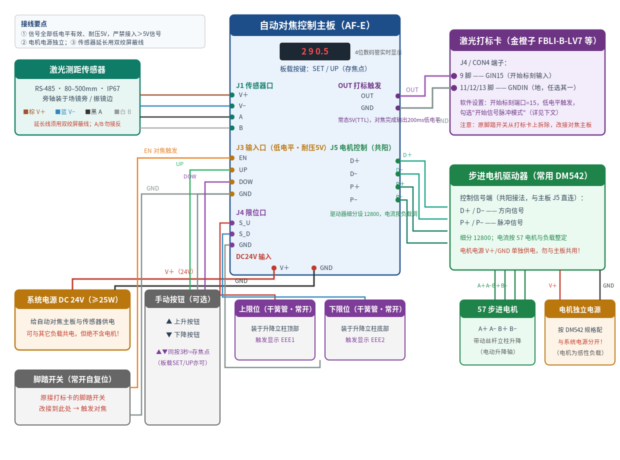
The figure below shows the complete wiring of the component: sensor → board J1; foot switch → board J3 (EN); manual buttons → J3 (UP/DOW, optional); reed switch upper and lower limits → J4; board J5 → DM542 driver; DM542 → 57 stepper motor; board OUT → start marking input of the marking card. Note that the system power supply and the motor power supply are independent of each other.
5. Terminal Definition Tables
5.1 Autofocus Control Board Terminals
| Terminal | Pin | Connects to | Description |
|---|---|---|---|
| J1 sensor port | V+ / V− / A / B | Sensor brown / blue / black / white wires (match the silkscreen) | Supplies power to the sensor and carries RS-485 communication; extensions must use twisted-pair shielded cable; if A/B are reversed communication fails |
| J3 input port | EN / GND | Foot switch normally-open contact (the original marking card foot switch rewired here) | Shorting triggers autofocus; self-resetting normally open |
| UP, DOW / GND | Normally-open contacts of the manual up and down buttons (optional) | Shorting moves up or down; hold both keys for 3 s to store the focus | |
| J4 limit port | S_U / S_D / GND | Upper and lower limit reed switches (normally open) | Connect the two wires of each reed switch to S_U + GND and S_D + GND; NPN limits must be checked by model and connected with a common ground |
| J5 motor port | D+ D− P+ P− | Same-named terminals on the DM542 driver | Common-anode wiring (TTL); set the driver to 12800 microsteps and adjust the current to the motor and load |
| OUT output | OUT / GND | Start marking input of the marking card (e.g. pin 9 GIN15 and pins 11/12/13 GND on J4) | 5 V TTL in the normal state, no load capability; a 200 ms low-level pulse is output when focusing is complete |
| Power terminals | DC24V+ / GND | System power supply 25 W or more | Motor power must be independent to avoid damage to the system from motor coil back-EMF |
5.2 Marking Card Side (measured pins of a JCZ FBLI-B-LV7)
| Pin | Signal | Connection |
|---|---|---|
| J4 pin 9 | GIN15 (general input) | Connect to board OUT |
| J4 pins 11/12/13 | GNDIN (controller ground) | Connect to board GND (any one pin) |
| Original foot switch position | GIN4 etc. | The foot switch has been rewired to J3 of the autofocus board; the original foot switch connector on the marking card is left unused |
Note: marking cards of other brands and models can also be used as long as they provide an external start marking input (low-level trigger, TTL compatible). The connection is the same — OUT to the start marking input and GND to common ground.
6. Marking Software Settings (EzCad2 / JCZ cards)
- Open the marking software and go to Parameters (F3) → Port: select 15 (GIN15) as the start marking port and Low Level as the trigger mode;
- Parameters (F3) → Other: tick Start signal pulse mode / Enable marking start signal latch mode (the board outputs a 200 ms low-level pulse, and with this option ticked triggering works normally; GIN4/14/15 used as low-speed inputs need a trigger time of 200 ms or more, and this board outputs exactly 200 ms);
- Save the parameters and restart the software for them to take effect.
7. Commissioning Steps (four steps after power-up)
- Power up: after the wiring is complete, power up the system; the display shows the current measured distance;
- Check the direction: press up/down and observe the direction in which the column moves; if the direction is reversed, move the jumper below the display to the other side and power up again;
- Store the focus: raise or lower the lens manually to the sharp focus position for a standard workpiece, then press and hold up + down for 3 s (with external buttons) to store the current position as the focus — the buzzer beeps 3 times to confirm (with the onboard keys: press SET until FXXX is shown, press UP to store, then press SET to return);
- Test the focus: change to a workpiece of a different height and press the focus pedal — the column moves automatically to find the focus and triggers marking when it arrives.
8. Fault Codes
| Display | Meaning | Action |
|---|---|---|
| EEE1 | Upper limit triggered | The column has reached the top; check the workpiece and focus setting, and confirm the limit switch wiring |
| EEE2 | Lower limit triggered | The column has reached the bottom; check whether the workpiece is too low and whether the sensor is blocked |
| EEE3 | Sensor out of range | The distance is outside 80–500 mm; aim the sensor at a workpiece surface within range |
9. Usage Precautions
- Independent power supply: the stepper motor is an inductive coil load and must be powered separately; never share a power supply with the autofocus board, otherwise motor back-EMF may damage the board;
- 5 V signal tolerance: all inputs of the board (EN/UP/DOW/S_U/S_D) are active low and tolerate 5 V; never connect 24 V or higher signals or the board will be destroyed (such damage is not covered by warranty);
- Sensor wiring: never reverse the A/B wires or short them to the power wires; extension cables must be twisted-pair shielded;
- Highly reflective materials: mirror-finish or brushed aluminium workpieces need the focus to be recalibrated;
- Limit switches: the supplied reed switch limits are normally open and must be fixed by the user at suitable positions on the column; limit switches are not covered by warranty;
- OUT port: TTL level signal only, no load capability; never connect relay coils, solenoid valves or other power loads.
10. FAQ
| Question | Answer |
|---|---|
| What focus accuracy can be achieved? | The system focus accuracy is ±0.1 mm, which meets the depth-of-focus requirement of the vast majority of marking applications; measurement error on workpieces of different colours is below 0.2% F.S. |
| The motorized column keeps moving in one direction — what could be the cause? | 1) Most common: sensor out of range (EEE3 shown) — the surface is beyond 80–500 mm so no value can be read, and the board moves upwards by default under the anti-collision logic until the upper limit stops it (section 6.2 of the manual); aim the sensor at a workpiece surface within range. 2) Limit switch not installed or wiring loose — on over-travel the column does not stop at the end and keeps pushing to the mechanical limit; make sure the reed switch limits are fixed and connected to J4. 3) Sensor A/B wires reversed or signal interference — the distance data is abnormal and the board moves in the wrong direction on a wrong distance; check the A/B wiring and confirm the extension cable is twisted-pair shielded. 4) External up/down button stuck closed — a welded contact keeps the motor moving in one direction manually; disconnect the button wires to verify. 5) Driver direction (D+/D−) signal abnormal — measure the D+/D− levels with a multimeter as described in section 6.1 of the manual. Troubleshooting order: read the fault code on the display first, then check the limits, and finally check the signal wiring. |
| After changing to a workpiece of a different height, the column first runs in one direction, hits the limit and then reverses — is that normal? | Normal behaviour, not a fault. The focus was calibrated for the previous workpiece, and after the new workpiece is loaded the distance from the sensor to the surface may instantly fall outside the 80–500 mm range, which triggers the out-of-range logic. Two typical cases: 1) the previous workpiece was focused at 150 mm and the next workpiece is 90 mm higher, so the distance becomes 150−90 = 60 mm, below the 80 mm minimum sensing distance; 2) the previous focus distance was 480 mm and the next workpiece is 50 mm lower, so the distance becomes 480+50 = 530 mm, above the 500 mm maximum sensing distance. The column then moves in one direction, reverses at the limit, and once the sensor distance is back within 80–500 mm focusing completes automatically — just wait, there is no need to power down or call for service. To reduce this situation: when installing the sensor, set the static distance to a standard workpiece surface near the middle of the range (for example around 250 mm) so that there is margin in both directions; if workpieces with very different heights are changed frequently, choose a column configuration with more travel margin. |
| What happens if the marked object is a transparent material? | The laser distance sensor relies on the diffuse reflection from the target surface, while transparent materials (glass, acrylic, clear film and so on) let most of the light pass straight through: the sensor may measure the back surface or even the worktable, or the front and back surface echoes may add up and make the reading jump, in which case the autofocus result is unreliable and the focus may even be set on the table. Suggested handling: 1) stick a small piece of matte tape or a contrasting mark at the marking position (remove it after marking) to give the sensor a stable reflective surface; 2) mirror-finish and highly reflective workpieces need the same treatment and a recalibrated focus; 3) if none of this is possible, use manual lifting to focus. In practice, frosted, sandblasted or dark-backed transparent parts work relatively well; pure mirror-finish transparent parts should not rely on autofocus. |
| What if a heavy CO₂ or UV laser is mounted on the column? | Choose a reinforced (rigid) column with 170–550 mm travel and replace the 57 stepper motor with an 86 stepper motor (higher torque), raising the driver current according to the rated parameters of the 86 motor. Light lasers work with the standard 57 motor; with a heavy load, a small motor will lose steps, lift weakly or drift in position. |
| How is the motor driver wired and how are the parameters set? | Wiring: connect D+/D− (direction) and P+/P− (pulse) from J5 of the board directly to D+/D− and P+/P− of the driver (this board uses common-anode wiring, so make sure the driver accepts common-anode inputs); connect the two motor phases to A+/A− and B+/B− on the driver. Parameters (57 stepper motor, 3 A rated, as an example): set the microstep value to 12800 and the current to the 3 A motor rating — on DM542-type drivers both current and microsteps are set with DIP switches (SW1–SW3 for current, SW4–SW6 for microsteps; refer to the table printed on the driver housing). For heavier loads the current can be raised slightly, but never above the motor rating. Important: the motor must be powered separately and must never share a supply with the autofocus board; after setup, press up/down manually to confirm the direction, and change the jumper if it is reversed. |
| The motor whines or stutters — what should I do? | 1) High-frequency whine or squeal: usually caused by the microstep value being set too low, so the pulse frequency falls into the audible band; raising the microsteps (12800 recommended) normally improves this noticeably. 2) Stuttering, vibration, weak force, inaccurate positioning: first increase the current within the driver rating (3 A for a 57 motor, more for heavy loads); if stuttering persists, check the A and B phase wiring of the motor — whether A+/A− and B+/B− are miswired, reversed or poorly connected, since a missing or reversed phase directly causes stuttering, vibration and lost steps. Also check: whether the pulse and direction signals (P+/P−, D+/D−) match the common-anode wiring, whether the motor shares a supply with the board (it must be independent), whether the coupling is loose and whether the screw is binding. If everything is correct and the problem remains, contact technical support. |
| My marking card is not a JCZ card — can it still be used? | Yes, as long as the card has an external start marking input (low-level trigger, TTL compatible). The connection is the same: board OUT to the start marking input, GND to common ground, and in the software point the start marking port to the corresponding input and select low-level triggering. |
| Should the sensor be mounted beside the f-theta lens or beside the galvo scanner? | Both positions are supported; an f-theta lens side bracket and a galvo side bracket are supplied, so choose the side with more room according to the machine structure (side-axis mounting). The key point: the sensor spot must fall inside the actual marking area and at the same working height as the marking focal plane, otherwise the measured distance does not represent the true focal position of the workpiece. |
| Nothing happens after pressing the pedal (no focusing and no marking)? | Check along the signal chain: 1) the EN input wiring on J3 and whether the foot switch shares a common ground; 2) the marking card software settings — whether the start marking port points to the input that the board OUT is connected to and whether Low Level trigger is selected (JCZ: F3 → Port → Start Marking, tick pulse mode); 3) whether the OUT port has been connected to a power load such as a relay (OUT is a TTL signal only, so miswiring gives no output); 4) whether the board and the sensor are powered normally and whether the display shows anything. |
| Are the upper and lower limit switches mandatory? | Strongly recommended. When out of range the system moves upwards by default and relies on the upper limit to stop it; without limits, an abnormal over-travel drives the column straight into the mechanical limit and may damage the screw, the coupling or even the laser. The supplied reed switch limits are normally open and must be fixed by the user at suitable positions on the column (limit switches are not covered by warranty). |
| Do I need to recalibrate the focus after changing to a workpiece of a different height? | No. The focus is calibrated once (raise or lower manually to the focus position, then hold up + down for 3 s to store it; the buzzer beeps 3 times to confirm). Afterwards, changing to a workpiece of a different height only requires pressing the pedal for automatic focusing — this is exactly the problem that autofocus solves. The focus only needs recalibrating when the f-theta lens is changed or the optical system is adjusted so that the focal plane position moves. |
| The manual up/down direction is reversed? | Power down, move the jumper below the display to the other side, and power up again. |
| Can automation cascading be implemented? | Yes. The OUT signal of the board can also be connected to other automation equipment such as a PLC; the system can work standalone or be networked and cascaded with multiple units. |
Disclaimer
The content of this page is for reference only; the product appearance, connector silkscreen and specifications are subject to the actual product and the supplied manual, and marking software menu names may differ slightly between software versions. Switch off the power before wiring and check the terminal silkscreen carefully; damage caused by wiring that does not follow the manual (for example over-voltage on an input, a motor sharing the system supply, or a power load on the OUT port) is not covered by warranty. Specifications are subject to change without notice.
Hotline: +86 159-2722-0467 | Website: www.soar-laser.cn | Images on this page: actual product photos and demo videos are supplied separately (installation and focusing videos available)





Reviews
There are no reviews yet.