


What Is Filter Coating? How to Pass Only Specific Wavelengths
Filter coating is an important concept in laser technology, widely used in industrial manufacturing, scientific research and healthcare. This article systematically introduces the core concepts, working principles, key parameters, main types and typical applications of filter coating, helping readers build a complete knowledge framework.
Table of Contents
- 1. What Is Filter Coating? Understanding the Core Concepts
- 2. Working Principle: How Is Filter Coating Applied?
- 3. Key Parameters: Understanding the Performance Indicators of Filter Coating
- 4. Main Types: What Kinds of Filter Coating Exist?
- 5. Applications: Where Is Filter Coating Used?
- 6. Common Misconceptions: Pitfalls to Avoid
1. Core Concepts: What Is Filter Coating?
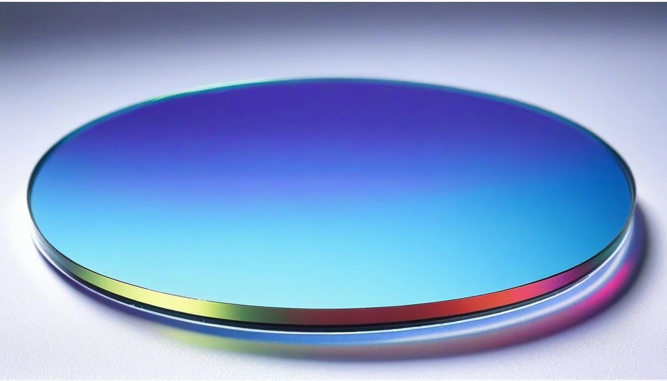
Filter coating is the thin-film coating used to manufacture all kinds of optical filters. Its core function is ‘light selection’—letting only certain wavelengths pass while blocking (reflecting or absorbing) the others. It is like an optical ‘sieve’: wavelengths that match pass through, and those that do not are held back. Filter coating is the most diverse category among interference coatings; from deep ultraviolet to far infrared, and from extremely narrowband to ultrabroadband, almost any spectral shape can be achieved through coating design. In laser and optical systems, filters perform key functions such as wavelength selection, noise suppression and spectral shaping, making them an important tool for ‘tuning’ an optical system.
2. Working Principle: How Is Filter Coating Applied?
The working principle of filter coating is based on multiple-beam interference. Like other dielectric coatings, it is formed by stacking alternating layers of high- and low-refractive-index films. Through careful design of the thickness and material of each layer, light of a specific wavelength can interfere constructively in the transmission direction (passing smoothly), while at other wavelengths it is canceled or reflected. Taking a bandpass filter as an example, its structure is usually similar to a Fabry–Pérot resonator—two high-reflection films with a spacer layer in between; only light whose wavelength exactly matches the resonance condition can pass, forming a very narrow transmission peak. Long-pass/short-pass filters are similar to making band-edge optimisation on the basis of a Bragg mirror, so that wavelengths on one side are highly transmitted and those on the other are highly reflected. Gradient-index Rugate filters (ripple filters) have a continuously varying refractive index, enabling cleaner spectral shapes with fewer sidelobes.
💡 An analogy
A filter coating is like a precise optical sieve—it lets only light of a specific colour (wavelength) pass and blocks all other colours. Some filters pass only a very narrow band (narrowband filters), while others block only a specific band (band-stop filters), just like sieves with different apertures sorting particles of different sizes.
In summary, filter coating involves the intersection of multiple disciplines including optics, materials science and precision manufacturing. Mastering its basic principles and key parameters is the foundation for properly selecting and using related products.
3. Key Parameters: Understanding the Performance Indicators of Filter Coating
Understanding filter coating requires mastering the following key parameters, which directly determine product performance and application scenarios:
| Parameter Name | Meaning | Why It Matters |
|---|---|---|
| Centre Wavelength (CWL) | — The central transmission wavelength of a bandpass filter | The centre position of the wavelengths a filter allows through, with accuracy typically required to ±1 nm or better |
| Bandwidth (FWHM) | — The full width at half maximum of the transmission peak, ranging from narrowbands below 1 nm to broadbands of hundreds of nanometres | Directly affects laser performance and the choice of application scenarios |
| Peak Transmittance | — The highest transmission ratio within the passband; the higher the better | Directly affects laser performance and the choice of application scenarios |
| Blocking Depth (Optical Density, OD) | — The degree of suppression in the stopband; OD4 means transmittance below 0.01% | How thoroughly light in the stopband region is blocked, expressed as optical density OD; OD6 means transmittance of only one part in a million |
| Edge Steepness | — How steep the transition from passband to stopband is; the steeper, the harder to make | Directly affects laser performance and the choice of application scenarios |
| Angle of Incidence Range | — A filter’s spectrum varies greatly with angle, especially a narrowband filter | Directly affects laser performance and the choice of application scenarios |
The above parameters are interrelated and mutually constrained. In actual selection, a comprehensive trade-off among performance, cost, reliability and other aspects is needed according to specific application requirements.
For more product parameters or selection advice, please contact the Soar Laser technical team.
4. Main Types: What Kinds of Filter Coating Exist?
Filter coatings can be classified in many ways. By spectral function: bandpass filters (BP)—pass only a certain band; band-stop/notch filters (BR/Notch)—block a specific band (such as a laser line) and pass the rest; long-pass filters (LP)—pass wavelengths longer than a certain value and block shorter ones; short-pass filters (SP)—pass wavelengths shorter than a certain value and block longer ones. By structure and material: all-dielectric interference filters—pure dielectric multilayers, with low absorption and high damage threshold; metal-dielectric hybrid filters—containing a thin metal layer, fewer layers but with absorption; Rugate filters—gradient filters with continuously varying refractive index, good sidelobe suppression and high damage threshold; soft-coated filters—an early thermal-evaporation process, low cost but poor stability. By bandwidth, they can also be divided into narrowband, mid-band and broadband filters.
5. Applications: Where Is Filter Coating Used?
Filter coatings have a very wide range of applications, covering industrial manufacturing, scientific research, healthcare, communications and information, and many other fields. The following introduces several main aspects:
- Filters are used in every field of optics and photonics. In laser technology, laser-line filters are used to purify the laser spectrum and remove amplified spontaneous emission (ASE)
- notch filters are used to block intense laser lines. In biomedical optics, filter sets (excitation filter + emission filter + dichroic mirror) are the core of fluorescence microscopes and flow cytometers
- Raman filters are used to separate the excitation light from the Raman-scattered light. In optical communications, wavelength-division multiplexing (WDM) filters combine and split optical signals of different wavelengths. In machine vision, bandpass filters enhance contrast in a specific band and suppress ambient-light interference. In spectrometers and instruments, various filters are used for wavelength selection. For salespeople, filters are a typical ‘parameters determine price’ product—the narrower the bandwidth, the deeper the blocking and the steeper the edge, the more the price rises geometrically.
Typical Application Scenarios in Detail
Scenario 1: Optical Communication Systems
narrowband filters in dense wavelength-division multiplexing (DWDM) systems are core components used to separate and combine optical signals of different wavelengths.
Scenario 2: Biomedical Optics
in biomedical equipment such as fluorescence microscopes, flow cytometers and PCR instruments, filter sets are used to separate excitation and emission light and improve the signal-to-noise ratio.
Scenario 3: Imaging and Photography
UV filters, IR-cut filters and neutral-density filters on camera lenses are used to improve image quality and control exposure.
Scenario 4: Laser Systems
laser-line filters are used for frequency selection and beam purification, and harmonic separators for separating fundamental and frequency-doubled light, both being common components in laser systems.
6. Common Misconceptions
Many people have somewhat plausible but mistaken notions about filter coating. See whether you fall into any of the following misconceptions:
Misconception 1: A filter only needs to be judged by ‘which wavelengths it passes.’
In fact, the depth of the stopband (OD value), the flatness of the passband and the steepness of the edge are all key indicators; a difference of one order of magnitude means a big difference in performance.
Misconception 2: Filters can be used at an angle.
The spectrum of an interference filter is very sensitive to the angle of incidence; as the angle increases, the centre wavelength blue-shifts (moves toward shorter wavelengths), especially for narrowband filters, so it must be used at the design angle.
Misconception 3: All filters ‘absorb’ the unwanted light.
Interference filters mainly reflect unwanted wavelengths rather than absorb them—which is why they can withstand high optical power—but the reflected light must be considered in system design, otherwise it may cause stray-light problems.
Misconception 4: The more expensive a filter, the better.
Filters have many performance indicators and should be chosen according to the actual application; for example, where spectral shape requirements are not high, an absorptive glass filter may be far more economical than an interference filter.
The above are several common misconceptions about filter coating. In practical applications, comprehensive judgment is needed based on specific product parameters and use conditions. If in doubt, it is recommended to consult a professional technician.
Leave a Reply