


What Is Gain? How the Amplification Capability of an Optical Amplifier Is Measured
Gain is the core physical quantity that measures the amplification capability of an optical amplifier: it describes by what factor the power of an optical signal grows after passing through the amplifier or the gain medium. Understanding the various definitions, units and calculations of gain is the foundation for studying optical amplifiers and lasers. This article covers the concept, the formulas, the classification and the applications of gain.
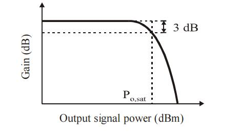
Table of contents
- 1. What is gain? Getting the core concept straight
- 2. Working principle: how is gain produced
- 3. Key parameters: reading the specifications of gain
- 4. Main types: what kinds of gain are there
- 5. Applications: where is gain used
- 6. Common misconceptions: points easily confused
1. Core concept: what is gain?
Gain is the core physical quantity in photonics for measuring how strongly light is amplified. In simple terms, it describes by what factor the power of an optical signal is raised after passing through an amplifier or a gain medium. It is one of the most basic parameters for assessing the performance of optical amplifiers and lasers.
The concept looks simple, but gain has several definitions and several ways of being expressed, and the meaning can differ from one context to another. Understanding those definitions, units and conversions properly is the foundation of amplifier and laser theory.
The magnitude of the gain sets the amplification quality, the transmission distance and the signal-to-noise ratio; in long-haul communication, laser systems and optical sensing it is often what limits the whole system. Only by understanding the several definitions and conversions of gain can every number on a datasheet be read correctly.
Gain is not the name of a class of device but a quantity describing amplification capability. The same amplifier can give gains several dB apart at different operating points, so a “gain” figure on a datasheet has to be read together with its test conditions: small-signal or saturated, at which wavelength, at what input power. Stripped of those conditions, the number means very little.
2. Working principle: how is gain produced?
Gain does not appear from nothing: it comes from the stimulated amplification of a signal in a gain medium after population inversion. To work out “how much it can amplify”, three steps are needed: calculate the gain per unit length, integrate it over the length of the medium to obtain the total gain, and then establish under what conditions that gain holds.
Step one: the gain coefficient g
The gain per unit length is written g = Nexc · σem, where Nexc is the density of active laser particles in the upper level and σem is the stimulated-emission cross-section. If the medium also shows reabsorption or scattering loss, the loss coefficient α has to be subtracted from the gain coefficient; only the net gain coefficient actually counts.
Step two: the total gain
After the light has travelled a distance L through the gain medium, the total gain follows from integrating the gain coefficient along the path. For a homogeneous medium the power amplification factor is exp(g·L), which in decibels is G = 4.34 · g · L. This is also why a fibre amplifier needs tens of metres of erbium-doped fibre while a semiconductor optical amplifier manages with a few millimetres of active region: the two differ in g by several orders of magnitude.
Step three: what the gain depends on
Gain is not a constant; it varies with at least the following four quantities:
- Pump intensity: the stronger the pump, the more particles sit in the upper level and the higher the gain, until the pump is exhausted
- Signal intensity: a stronger signal consumes upper-level particles, so the gain falls — this is gain saturation
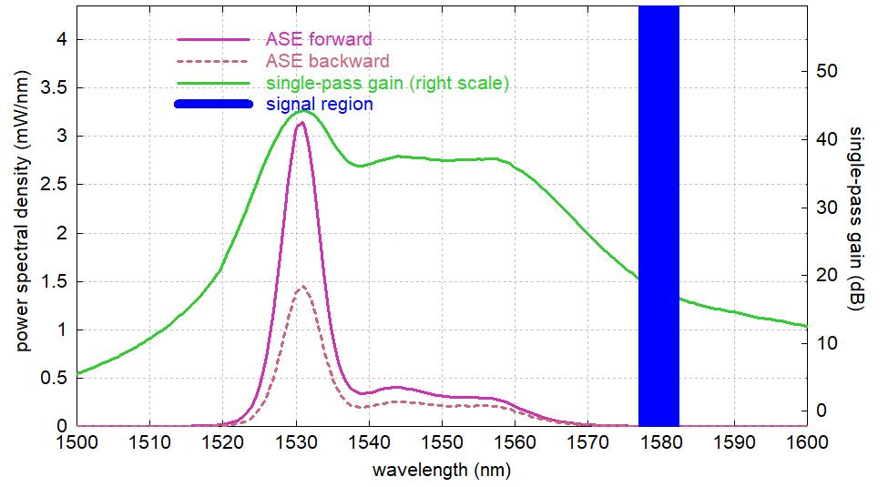
- Wavelength: the emission cross-section differs from wavelength to wavelength, so the gain varies with wavelength and forms a gain spectrum
- Temperature: temperature changes the level populations and the emission cross-section, and with them the magnitude and the shape of the gain
◆ An analogy
If an optical transmission system is a marathon relay race, gain is the “refuelling station” along the route — it does not change the direction of the run (the propagation direction of the light), but it tops up the energy of the tired runners (the attenuated optical signal) so that they can finish the course. The quality of the refuelling station (the noise figure (NF) and the gain of the amplifier) determines the final result.
In one sentence, the physics of gain compresses to this: population inversion supplies energy that can be drawn upon, the signal takes it away by stimulated emission, the rate at which it is taken is proportional to the particle density and the emission cross-section, and multiplying by the length of the medium gives the total gain. Every parameter of gain merely describes how that product changes under different conditions.
These quantities are coupled: more pump raises the gain but also the spontaneous-emission noise; widening the gain spectrum costs peak gain; and pushing the output into saturation compresses the gain and distorts the pulse shape. A serviceable amplifier is the result of balancing gain, noise, bandwidth and power against one another.
3. Key parameters: reading the specifications of gain
◆ The gain formula

Gain G is defined as the ratio of output power to input power. Expressed in decibels, the power gain is 10·log₁₀(power ratio) and the amplitude (field) gain is 20·log₁₀(amplitude ratio).
The difference comes from the square relationship between power and amplitude: P ∝ E².
What really has to be understood on a datasheet is the set of figures below. The table lists the core specifications of gain and what each one means:
| Parameter | Meaning | Practical significance |
|---|---|---|
| Small-signal gain | The maximum gain when the input signal is extremely weak and the gain is not saturated; the inherent amplification capability of the amplifier | Sets how far a weak signal can be raised and is the core figure for a preamplifier |
| Gain coefficient g | The gain per unit length, in 1/m or dB/m; g = Nexc · σem, proportional to the upper-level population density and the emission cross-section | An intrinsic property of the gain medium that reflects how strongly the material amplifies; the gain coefficient multiplied by the medium length gives the total gain |
| Gain bandwidth | The wavelength range over which the gain stays above a specified value, usually half the peak value, that is 3 dB | Sets how wide a spectrum the amplifier can amplify at once and is a key figure for WDM systems and ultrafast pulse amplification |
| Gain flatness | The largest ripple of the gain within the specified bandwidth, in dB | Sets how consistent the power is from channel to channel in a multi-wavelength system; the poorer the flatness, the greater the spread in signal-to-noise ratio between channels |
| Gain efficiency | The small-signal gain produced per unit of pump power, in dB/mW | Reflects how efficiently pump energy is converted into gain; the higher the efficiency, the less pump power is needed for a given gain |
◆ A note on the decibel: the dB value of a power gain is 10 × log₁₀(Pout/Pin).
10 dB = a factor of 10, 20 dB = 100, 30 dB = 1000 and 40 dB = 10 000.
Note that a power ratio uses 10·log while an amplitude (field) ratio uses 20·log; the two must not be confused.
These parameters involve clear trade-offs: small-signal gain against saturation power, gain efficiency against gain bandwidth, peak gain against flatness — each pair pulls in opposite directions, so a high-gain design tends to be narrow-band and a wideband design tends to be less efficient. No single number can therefore be used to judge an amplifier.
If some of these parameters are unfamiliar, the Soar Laser product pages carry detailed specifications, and our technical engineers can advise on selection directly.
4. Main types: what kinds of gain are there?
Gain can be classified along several dimensions, each of which offers a different angle. Here are four ways: by signal strength, by spatial distribution, by physical mechanism and by spectral behaviour.
By signal strength
Small-signal gain
The input signal is very weak and does not disturb the inversion, so the gain is at its highest
Large-signal gain
The input signal is comparatively strong, the gain is partly saturated and the value falls
By spatial distribution
Local gain coefficient
The gain per unit length, in 1/m or dB/m; a local property of the material
Overall gain
The total amplification factor of the amplifier or the gain medium as a whole, in multiples or dB
By physical mechanism
Laser gain
Gain based on stimulated emission, as in fibre amplifiers and semiconductor amplifiers
Raman gain
Gain based on stimulated Raman scattering
Parametric gain
Gain based on parametric amplification through a second-order nonlinear effect
By spectral behaviour
Peak gain
The gain at the highest point of the gain spectrum
3 dB bandwidth
The wavelength range over which the gain falls to half its peak value
Gain flatness
The largest ripple of the gain within the specified bandwidth
Each type has its own advantages and drawbacks, and there is no absolute “best”, only what “fits”. Preamplification cares about small-signal gain, power amplification about saturated output power, WDM systems about gain bandwidth and flatness, and ultrafast pulse amplification also has to account for gain dispersion and gain narrowing. Different applications weigh the gain parameters quite differently.
5. Applications: where is gain used?
The concept of gain runs through everything from device design to system integration. By main field it divides into the following categories:
- Optical amplifier design: gain is the central design figure of an optical amplifier and sets how much it can amplify and how much output power it can deliver. Different applications need different gain levels — a preamplifier needs high gain, a power amplifier needs a high saturated output power.
- Laser design: in a laser the gain must exceed the total loss before oscillation can start (the threshold condition). The magnitude of the gain determines the output power, the efficiency and the dynamic behaviour of the laser.
- Optical communication systems: gain sets the spacing and the number of amplifiers along a link, while gain bandwidth and flatness set the channel count and the performance consistency of a WDM system.
- Ultrashort pulse amplification: during pulse amplification the gain varies with time through gain saturation, which affects the shape and the energy of the pulse. Understanding the dynamic behaviour of gain is essential to ultrafast amplifier design.
- Fibre sensing: the magnitude of the gain directly affects the detection sensitivity and the dynamic range of a sensing system.
Typical application scenarios
Scenario 1: optical amplifier design
Gain is the central design figure of an optical amplifier and sets how much it can amplify and how much output power it can deliver. Different applications need different gain levels — a preamplifier needs high gain, a power amplifier needs a high saturated output power.
Scenario 2: laser design
In a laser the gain must exceed the total loss before oscillation can start (the threshold condition). The magnitude of the gain determines the output power, the efficiency and the dynamic behaviour of the laser.
Scenario 3: optical communication systems
Gain sets the spacing and the number of amplifiers along a link, while gain bandwidth and flatness set the channel count and the performance consistency of a WDM system.
Scenario 4: ultrashort pulse amplification
During pulse amplification the gain varies with time through gain saturation, which affects the shape and the energy of the pulse. Understanding the dynamic behaviour of gain is essential to ultrafast amplifier design.
Scenario 5: fibre sensing
The magnitude of the gain directly affects the detection sensitivity and the dynamic range of a sensing system.
◆ Want to see more real application cases involving gain? Visit the application case page of Soar Laser, or contact our technical team directly for professional advice.
6. Common misconceptions
Several fairly widespread but inaccurate beliefs circulate about gain, and they need to be cleared up one by one:
Misconception 1: gain is just an amplification factor, so it is always a plain multiple
Gain has several forms of expression. Small gains are often quoted as a percentage, moderate gains as a multiple and large gains in decibels; there is also the gain coefficient per unit length. The context and the unit both matter, and the logarithmic relation between dB and a plain multiple must not be confused.
Misconception 2: gain is a fixed number
Gain is not a constant. It varies with pump power, signal power (gain saturation), wavelength (the gain spectrum), temperature and polarisation. The amplifier gain normally quoted is the small-signal gain under a particular set of conditions; in service the gain can be different.
Misconception 3: the higher the gain, the better the amplifier
High gain is only one figure of merit; the noise figure, the saturated output power and the gain bandwidth matter just as much. Excessive gain usually brings more severe ASE noise and can even provoke parasitic oscillation. In practice the gain level has to be designed to suit the requirement.
Misconception 4: the gain formula is the same for every kind of gain
Different mechanisms have different gain formulas. The basic laser-gain expression is g = N·σ, whereas Raman gain and parametric gain obey entirely different expressions that depend on pump intensity and nonlinear coefficients. One formula cannot be used to understand every kind of gain.
The misconceptions about gain go well beyond these. New gain media and new pumping schemes keep appearing, so earlier rules of thumb may no longer hold. If you have other questions, leave a comment and we will answer them one by one.
◆ Recommended reading
- What Is Gain Saturation? Why an Amplifier Cannot Amplify Indefinitely
- What Is a Noise Figure? Why an Amplifier Adds Noise
- What Is an EDFA? The Signal Refuelling Station of Fibre Communication
- What Is ASE? Where the Noise Light in an Amplifier Comes From
- What Is an Optical Amplifier? Amplifying a Weak Optical Signal Directly
Leave a Reply