


What Is an Optical Lens? The Focusing Element of Every Laser System
A lens is the least conspicuous piece of glass in a laser system and the one that most affects the result. Two curved surfaces bend a plane wavefront into a spherical one, squeezing a beam tens of millimetres wide down to tens of micrometres, or straightening a diverging beam at a focal length of a few millimetres. What decides whether a lens works is not its focal length alone but four things: how much power the material and coating can take, how much aberration survives in your beam path, whether the clear aperture crops the edge of the beam, and whether the figure you ordered is the EFL or the BFL. This article starts from refraction and wavefronts, gives the lensmaker equation and the ABCD matrix, then works through aberrations, NA and f-number before turning to types, combinations and the usual mistakes.
Contents
- 1. The Core Concept: What Is an Optical Lens?
- 2. How It Works: Refraction, Wavefront and Focal Length
- 3. Key Parameters: Reading a Lens Specification
- 4. Aberrations and Light-Gathering Power: What Really Sets Spot Quality
- 5. Main Types and Common Combinations
- 6. Applications: Where Lenses Are Used
- 7. Common Misconceptions: Six Widely Held Myths
1. The Core Concept: What Is an Optical Lens?
An optical lens is a component made of transparent material that changes the direction of light with one or two curved surfaces, producing focusing, divergence, collimation or imaging. Its job can be put in one sentence: it reshapes the wavefront. A plane wavefront becomes spherical after passing through a converging lens, and the centre of that sphere is the focal point; conversely a spherical wavefront leaving the focal point is flattened by the same lens. Almost every optical system depends on this, and in a laser system the three common uses are focusing, collimation and beam expansion.
Compared with a mirror, a lens keeps the beam straight, packs the layout tight and tolerates alignment errors. It has two drawbacks: the material itself absorbs, and its refractive index varies with wavelength, which brings chromatic aberration. Those two facts mark the boundary of lenses at high power and over wide bands, and they are why a kilowatt cutting head often prefers reflective focusing: to avoid absorption and thermal lensing.
The choice of material follows the wavelength and the power. From the visible to the near infrared, N-BK7 (n ≈ 1.517, cheap and homogeneous) and high-purity fused silica (n ≈ 1.459, transparent from ultraviolet to near infrared, low expansion and a high damage threshold) dominate. Deeper into the ultraviolet, CaF₂ (n ≈ 1.434) or MgF₂ is needed. At the 10.6 μm of a CO₂ laser only ZnSe (n ≈ 2.4), Ge (n ≈ 4.0) or Si (n ≈ 3.4) will do, and ZnSe is the most common because it absorbs little and transmits visible light, which makes alignment easy. Once the material is fixed, the tolerable power density, the strength of thermal lensing and the price are largely fixed too.
2. How It Works: Refraction, Wavefront and Focal Length
2.1 Refraction and wavefront curvature
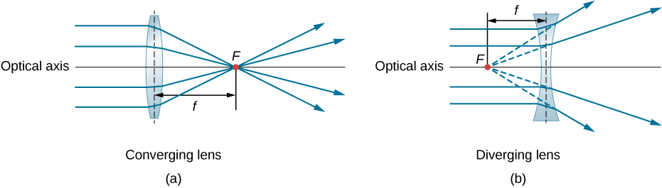
Light entering another medium at an angle bends, and the amount is given by n₁sinθ₁ = n₂sinθ₂. On a lens both surfaces meet the axis at a different angle everywhere, so rays at different heights bend by different amounts: rays near the rim bend more, rays near the centre hardly at all. Those differently bent rays meet behind the lens at one point, the focal point; if they only appear to meet when traced backwards, the point is virtual and the lens is diverging.
Wave optics says the same thing in a clearer way. A lens imposes a different phase delay at different positions. A convex lens is thicker at the centre, so light there is delayed more and the originally flat wavefront curves inwards into a sphere; a concave lens is thinner at the centre and the wavefront curves outwards. Focusing is simply matching the curvature of the wavefront to the distance to the focal point.
2.2 The lensmaker equation and its sign convention
Focal length follows from the two radii of curvature, the refractive index of the material and the thickness of the lens. This is the lensmaker’s equation; in the thin-lens approximation, where thickness is much smaller than either radius, it reduces to:
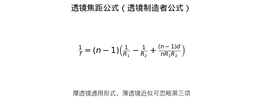
Figure 1: the lensmaker equation for a thick lens. In the thin-lens approximation (thickness d much smaller than R₁ and R₂) the third term can be ignored and the expression reduces to 1/f = (n−1)(1/R₁ − 1/R₂).
The sign convention, in the Cartesian form, is where most mistakes happen. Light travels from left to right; a radius is positive when its centre of curvature lies to the right of the vertex and negative when it lies to the left. A biconvex lens has R₁ > 0 and R₂ < 0, so 1/R₁ − 1/R₂ = 1/R₁ + 1/|R₂|: both terms add with the same sign and f is positive, a converging lens. A biconcave lens subtracts the two terms and f comes out negative. A meniscus has two radii of the same sign, so its focal length can be positive or negative depending on the thickness and the difference between the radii, which is exactly why meniscus elements are useful for aberration control.
2.3 EFL and BFL: two numbers both called focal length
The effective focal length (EFL) is measured from the principal plane and is the standard description of light-gathering power. The back focal length (BFL) is measured from the last surface and is the number the mechanical design actually needs. In a thin lens the two are nearly equal; in a thick lens or a group they can differ by several millimetres. A plano-convex lens with f = 100 mm may have a BFL of only about 96 mm. Always confirm which one a datasheet quotes, or the focus will be systematically offset.
2.4 The ABCD matrix of a thin lens
In paraxial optics a ray is described by a vector of its height y and its angle θ to the axis, and each element becomes a 2×2 matrix. A thin lens is [[1, 0], [−1/f, 1]]: the height is unchanged and the angle changes by −y/f. Multiplying the matrices of all elements in order gives the transfer matrix of the whole system, which is the standard way to analyse beam expanders, scanning systems and resonators, far quicker than tracing every surface.
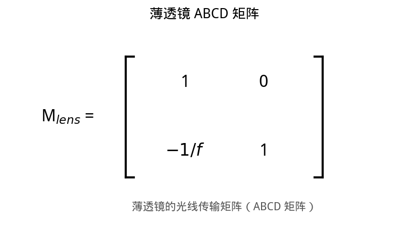
Figure 2: the ABCD matrix of a thin lens acting on the ray vector [y, θ]ᵀ, where y is the height and θ the angle to the axis
2.5 How small a focused spot a Gaussian beam makes
Laser light is not parallel light, so it has to be treated as a Gaussian beam. A beam of diameter D (1/e²) and beam quality M², focused by a lens of focal length f, gives a focal spot of 1/e² diameter d = 4λfM²/(πD). Three conclusions follow: the spot scales with focal length, inversely with the incident beam diameter, and directly with M². To shrink the spot, the effective move is not a shorter focal length but expanding the beam until it nearly fills the clear aperture, which is why high-power cutting heads always carry a beam expander in front.
Depth of focus matters just as much. The Rayleigh length is z_R = πw₀²/(λM²), so a smaller spot means a shorter depth of focus and tighter demands on workpiece height and fixturing. A short focal length is therefore the right answer for thin sheet and the wrong one for thick plate, where lack of depth of focus costs more than the smaller spot gains.
3. Key Parameters: Reading a Lens Specification
A lens datasheet usually carries a dozen numbers, but only a few of them cause a project to be redone. One rule applies throughout: no figure means anything without the wavelength and the beam diameter beside it.
| Parameter | What it means | Why it matters |
|---|---|---|
| Effective focal length (EFL) | Distance from the principal plane to the focus; sets spot size and working distance | A short focal length gives a small spot but a shallow depth of focus and little working distance; a long one does the opposite. Thin sheet takes a short lens, thick plate and deep-hole drilling take a long one, and room for spatter protection has to be left as well. |
| Back focal length (BFL) | Distance from the last surface to the focus | This is the number mechanical design works with. A thick lens has a distinctly shorter BFL than EFL, and using the wrong one shifts the whole focal plane: on thin sheet it shows up immediately as incomplete cut or burning. |
| Numerical aperture (NA) | NA = n·sinθ, where θ is the maximum half-angle of convergence | Sets the diffraction-limited spot (d ∝ λ/NA) and the depth of focus. A larger NA means a smaller spot and a shorter depth of focus. For fibre coupling the NA must also match the acceptance angle of the fibre, or coupling efficiency halves. |
| f-number (f/#) | Ratio of focal length to clear aperture, f/# = f/D | The reciprocal of NA in the small-angle limit, NA ≈ 1/(2·f/#). An f/1 lens gathers a lot of light but is hard to correct, and below about f/8 spherical aberration takes over. This is a hard design trade-off. |
| Clear aperture (CA) | The optically usable diameter, normally smaller than the mechanical outside diameter | The incident beam, including any divergence margin, has to fit inside the CA. Cropping the edge adds diffraction rings, pushes energy into the outer halo and overheats the rim. |
| Material and refractive index | Sets transmission band, dispersion, thermo-optic coefficient and damage threshold | N-BK7 is general purpose, fused silica takes high power and ultraviolet, CaF₂ covers the deep ultraviolet, and ZnSe, Ge or Si serve the mid-infrared. At high power also check dn/dT, which governs how fast thermal lensing drifts. |
| Coating (AR / HT) | An antireflection coating cuts the roughly 4% single-surface reflection to the 0.1% level | Uncoated on both faces, a BK7 lens throws away 8% for nothing. A coating is designed for a wavelength and an angle, and reflectance rises away from that point. At high power check the coating damage threshold, not just the transmission. |
| Surface figure and quality | Figure quoted as λ/10 or λ/4, surface quality as 10-5 or 20-10 | A figure error turns directly into wavefront error and spot broadening, while surface defects scatter light and lower the threshold. Precision imaging asks for λ/10 and 10-5; λ/4 and 40-20 are usually enough for focusing. |
| Laser-induced damage threshold (LIDT) | Continuous power or pulse energy density the coating can take per unit area | Work it out at the focus, not as an average over the substrate. For pulsed light the mechanism depends on pulse duration: nanoseconds are limited by absorbing defects, femtoseconds by multi-photon ionisation, and the two sets of numbers cannot be swapped. |
| Operating wavelength range | The combined result of material transmission and coating design | A material that transmits but a coating that does not is useless. Multi-wavelength systems such as 1064 plus 532 nm need a dedicated broadband coating; a single-wavelength one will not do. |
4. Aberrations and Light-Gathering Power: What Really Sets Spot Quality
4.1 Five geometrical aberrations and two kinds of chromatic error
A spherical lens cannot bring light to a perfect point. There are five ways imaging departs from the ideal, plus chromatic aberration, and in practice one or two of them dominate any given system:
- Spherical aberration: marginal rays converge earlier than paraxial ones, so the focus is smeared along the axis. It grows as the f-number falls and the aperture rises. For single-wavelength laser focusing this is the dominant term.
- Coma: an off-axis point images as a comet-shaped smear, asymmetric above and below. It appears as soon as the field angle grows and is the usual reason spot shape degrades at the edge of a scanning field.
- Astigmatism: the tangential and sagittal planes have different focal lengths, so a point source becomes two perpendicular focal lines. Tilting a lens or using an asymmetric surface produces it.
- Field curvature: the best image surface is curved rather than flat, so the edge of a flat detector, such as a camera sensor or a galvanometer working plane, is naturally out of focus.
- Distortion: image position shifts, pincushion or barrel, without loss of sharpness. It affects dimensional accuracy, not resolution.
- Axial and lateral chromatic aberration: the refractive index varies with wavelength, so different colours focus at different distances (axial) or at different magnifications (lateral). Broadband imaging and femtosecond pulses suffer most from this one.
Match the aberration to the job: single-wavelength laser processing, such as 1064 nm cutting, welding or marking, has to deal with spherical aberration almost alone, which is why an aspheric singlet often beats an achromatic doublet: fewer elements, less absorption, a smaller spot. In broadband imaging, femtosecond lasers and multi-wavelength common-path systems the chromatic terms dominate instead, and an achromat, an apochromat or a reflective system is required. Mirrors have no chromatic aberration at all.
4.2 NA and f-number: two ways of writing the same thing
Light-gathering power is normally written as NA = n·sinθ, where n is the refractive index between lens and sample (about 1 in air) and θ is the largest angle between a marginal ray and the axis. The other way is the f-number, f/# = f/D. In the small-angle limit the two are reciprocal, NA ≈ 1/(2·f/#).
These two numbers matter because they lock down three things at once: the diffraction-limited spot (proportional to λ/NA), the depth of focus (proportional to λ/NA²) and the beam divergence the lens can accept. A smaller spot means a shorter depth of focus and less alignment margin. There is no free resolution.
5. Main Types and Common Combinations
5.1 By shape: five basic forms
- Biconvex: both surfaces converge, giving a short focal length and strong power; suited to imaging and collimation, and relatively easy to balance for spherical aberration.
- Plano-convex: one flat and one convex surface, low cost, and lowest spherical aberration when the convex side faces the incoming collimated beam. This is the workhorse for laser focusing and fibre collimation.
- Biconcave: both surfaces diverge; used for beam expansion and for adjusting divergence.
- Plano-concave: one flat and one concave surface, usually paired with a plano-convex element in a Galilean expander.
- Meniscus: two radii of the same sign, so it can be positive or negative; also common as a high-power window that adds mild focusing, because its spherical aberration is lower than that of a plano-convex element.
5.2 By function: from a single element to a special-purpose lens
- Singlet: the simplest construction and the fullest set of aberrations; used alone only where spot quality is not critical.
- Achromatic doublet: a crown-glass convex element cemented to a flint-glass concave one, suppressing axial colour and spherical aberration together. It is the general-purpose standard lens.
- Apochromat: three or more elements in special glasses, bringing three wavelengths to a common focus; used in microscopy and high-precision imaging.
- Asphere: the surface is an optimised curve rather than a sphere, so a single element can correct spherical aberration and focus close to the diffraction limit, reducing element count and absorption.
- Cylindrical lens: has power in one direction only, turning a round spot into a line for laser scribing, line scanning and sheet-of-light illumination.
- Graded-index (GRIN) lens: the index varies radially and the faces are flat; typical parts are only 1–2 mm across and are dedicated to fibre collimation and coupling.
- Infrared lens: ZnSe, Ge, Si or CaF₂ for CO₂ lasers and thermal imaging. Germanium is opaque in the visible, so a separate visible alignment path is needed during setup.
5.3 Combinations: what one element cannot correct, two can
- Doublet and triplet: materials of different dispersion are cemented together so that the chromatic errors of the elements cancel, while the spherical load is shared.
- Galilean expander: a concave element followed by a convex one, with no real focus between them. It is short and there is no focal point to burn, so it is the first choice for high power.
- Keplerian expander: two convex elements with a real focus between them, where a pinhole can be placed for spatial filtering to improve beam quality. At high power the air at that focus may break down, so purging or evacuation is needed.
- f-θ scan lens: designed so that y = f·θ, making image position linear in galvanometer angle. An ordinary lens gives f·tanθ, which stretches the field at the edges and is the reason marked dimensions come out wrong on a scan system.
- Telecentric f-θ lens: adds a telecentric design so the chief ray strikes the work surface parallel to the axis across the whole field. Spot size stays uniform and drilled holes show no taper, which suits precision marking and PCB processing.
6. Applications: Where Lenses Are Used
From the cutting head to the fibre connector, the role a lens plays can be classified by which property of the beam it changes:
- Focusing: compressing a collimated beam into a small spot for cutting, welding, marking and drilling. Spot size and depth of focus are the pair that must be satisfied together.
- Collimation: turning the diverging output of a diode laser or a fibre into parallel light; the core function of a fibre laser output head or collimator.
- Beam expansion and reduction: adjusting beam diameter to match the clear aperture of downstream optics while compressing divergence, so that the spot survives a long propagation path.
- Fibre coupling: launching laser light into a fibre, which requires the spot to match the core diameter and the NA to stay below the acceptance angle, otherwise return loss and heating both climb.
- Imaging and inspection: machine-vision objectives, endoscopes and microscopes bring the various aberrations close to the diffraction limit by combining several elements.
- Beam shaping: cylindrical groups turn a Gaussian round spot into a uniform line or a flat-top profile for laser annealing, scribing and photovoltaic processing.
- Fourier transform and information processing: a lens performs the spatial Fourier transform in its focal plane, which is the physical basis of optical correlation, holography and 4f systems.
7. Common Misconceptions: Six Widely Held Myths
Lens specifications look like a set of bigger-or-smaller choices, and that is where most misconceptions start.
Misconception 1: The shorter the focal length, the better
A short focal length does give a smaller spot, but the depth of focus shrinks as NA² and the working distance shortens, so the element is more exposed to spatter and to back-reflected light from the workpiece. Thick plate, deep-hole drilling and robot arms that vibrate all do better with a longer lens. Work out depth of focus and fixture clearance first, then look at spot size.
Misconception 2: The focal length of a lens is fixed
Focal length changes with wavelength, because refractive index does, and that is chromatic aberration. It also changes with temperature, because dn/dT is not zero. At high power the element absorbs light and warms up, so the focus drifts slowly: after a while the kerf widens or the cut stops going through. That is thermal lensing, and fused silica resists it far better than BK7, but the optical design still has to allow for compensation.
Misconception 3: An asphere is always better than a sphere
An asphere is genuinely stronger for monochromatic, low-aberration work, but it is hard to make, hard to test, expensive, and far more sensitive to decentre: mount it off axis and the advantage disappears. Ordinary imaging, illumination and general collimation are better served by spherical elements and cemented groups. The asphere earns its price only where single wavelength, diffraction-limited performance and a reduced element count all hold at once.
Misconception 4: Focal length is the distance from the lens surface to the focus
Not quite. The effective focal length is measured from the principal plane, which may lie inside the element or even outside it; the distance from the last surface is the back focal length. In thick elements and groups the two can differ by several millimetres. If a datasheet does not say which one it quotes, the assembled focus will be systematically offset.
Misconception 5: A lens can only focus, not collimate
Focusing and collimation are the same lens seen from two directions. Light leaving the focal point becomes parallel after the lens, which is collimation; parallel light converges to the focal point, which is focusing. The path is reversible, so the same element serves as collimator or focusing lens depending only on whether the source sits at the focus or at infinity.
Misconception 6: An AR coating works across the whole spectrum
An antireflection coating is designed for a particular wavelength and angle of incidence. Away from that point reflectance climbs from 0.1% back to a few per cent, and across ten surfaces that becomes a serious loss and a serious return loss. Broadband coatings do cover a range, but their average reflectance is usually higher than that of a single-wavelength design. State the wavelength and the angle of incidence when ordering; ‘AR coated’ on its own is not a specification.
Leave a Reply