


What Is an Optical Mirror? The Steering Wheel of Light in a Laser System
A mirror is the one component in a laser system that does a single job: it sends light back where it came from. It looks simple and is extremely hard to make. A high-reflectance cavity mirror must reach 99.99%, and the remaining 0.01% of loss, split into transmission, absorption and scatter, sets the finesse, the threshold and the output power of the cavity. At kilowatt level that same 0.01% of absorption is enough to distort the coating thermally. This article starts from the two reflection mechanisms, breaks the loss down into its parts, compares metal and dielectric coatings item by item, and then explains the two parameters most often chosen wrongly: damage threshold and radius of curvature.
Contents
- 1. The Core Concept: What Is an Optical Mirror?
- 2. How It Works: Where Reflection Comes From
- 3. Key Parameters: Reading a Mirror Specification
- 4. In Depth: Loss, Coatings, Damage Threshold and Curvature
- 5. Main Types: The Mirror Family
- 6. Applications: Where Mirrors Are Actually Used
- 7. Common Misconceptions: Six Widely Held Myths
1. The Core Concept: What Is an Optical Mirror?
An optical mirror is the component that sends incoming light back according to the law of reflection: the angle of reflection equals the angle of incidence, and both rays lie in the same plane of incidence. That law is taught at school, but its weight inside a laser system is something else entirely. A mirror is not an accessory; it decides whether the resonator reaches threshold, where the beam travels, and how much loss the cavity carries. The two most expensive optical parts in most lasers are the two cavity mirrors.
The first number that describes a mirror is its reflectance R, the ratio of reflected to incident power. A household mirror, silver then copper then protective paint, viewed through the glass, reflects about 85–90%. An industrial aluminium coating reaches roughly 90%. A dielectric high reflector for a laser cavity sits above 99.9%. The supermirrors built for cavity ring-down and for gravitational-wave detection reach 99.999%. That sounds like a small step, but pulling the loss down from 1000 ppm to 10 ppm raises the finesse of a cavity by two orders of magnitude.
Physically a mirror is three layers: substrate, coating and, optionally, a protective overcoat. The substrate sets the thermal and mechanical behaviour. BK7 is cheap, with a thermal expansion of about 7.1×10⁻⁶/K. Fused silica covers the ultraviolet to the near infrared and brings expansion down to 0.5×10⁻⁶/K. ULE or glass-ceramic reaches the 0.03×10⁻⁶/K level and is used for ultrafast and ultra-stable cavities. Silicon and silicon carbide conduct heat well enough for high power, and copper conducts it best of all, which is why CO₂ laser mirrors are often water-cooled copper. The expansion coefficient of the substrate governs coating stress and thermal lensing at high power, and it is the item most often left out of a specification comparison.
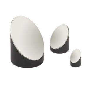
Compared with a lens, a mirror has two inherent advantages: no chromatic aberration and no absorption in the material. Light never enters the substrate, so broadband, large-aperture and high-power systems all prefer the reflective route, which is how large telescopes, high-power CO₂ cutting heads and terahertz beam lines are built. The price is alignment sensitivity: rotate a mirror by θ and the reflected beam moves by 2θ, so a mounting error is doubled. Surface figure has to be tighter as well, because a wavefront error accumulates twice on reflection.
2. How It Works: Where Reflection Comes From
2.1 Metal coatings: free electrons bounce the light back
The free-electron gas in a metal oscillates collectively under the driving field of the incoming light, and the oscillating charge radiates again, forming the reflected wave. As long as the optical frequency stays below the plasma frequency of the metal, the process works across the whole band, which is why a metal mirror is broadband by nature. Aluminium has its plasma edge deep in the ultraviolet, near 82 nm; in practice it covers roughly 250 nm to 10 μm, reflects about 90% in the visible, dips near 800 nm through interband absorption and climbs back above 95% beyond 1 μm. Silver reflects best in the visible, up to 98%, but tarnishes and darkens. Gold approaches 99% beyond 700 nm and falls away sharply below 550 nm because of interband transitions, which is precisely why gold looks yellow.
Metal coatings have two shortcomings that no design work can remove. The first is absorption: a few per cent sounds harmless at low power, but at kilowatt level it means tens of watts of heat deposited in a coating a few micrometres thick. The second is softness: aluminium and gold scratch easily, so a SiO₂ or MgF₂ overcoat is normally added, at the cost of one or two percentage points of reflectance. Silver mirrors are usually built as silver plus a few dielectric layers, which keeps the high visible reflectance while slowing the tarnishing.
2.2 Dielectric coatings: making every interface reflection add in phase
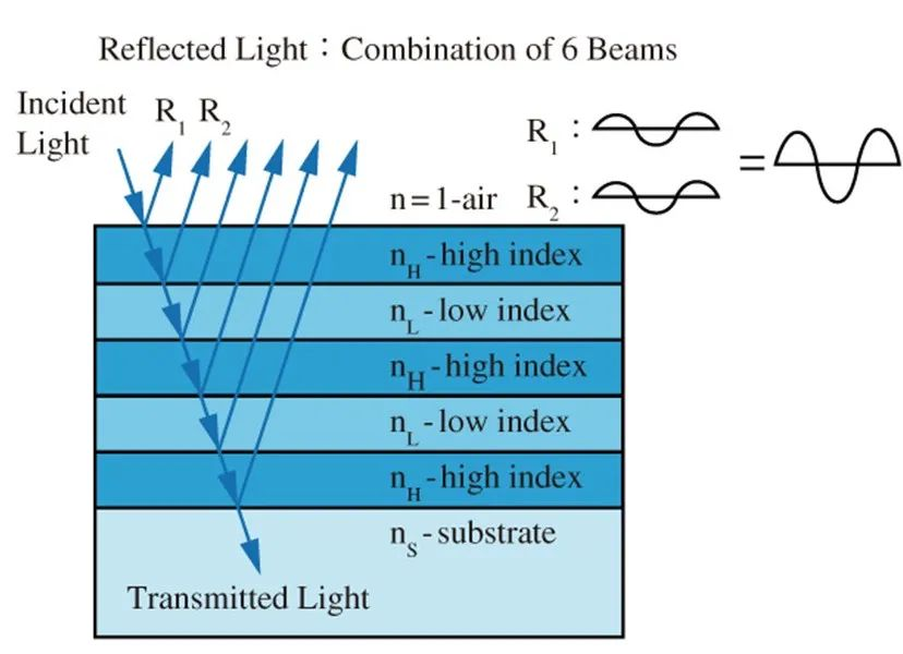
A single glass surface reflects only about 4%, and most of the light passes straight through. But if high- and low-index materials are stacked alternately in quarter-wave optical thickness, the reflection from each interface returns to the front surface in phase with the others and adds constructively. That is the whole secret of a dielectric high reflector: not one strongly reflecting material, but dozens of interfaces adding up in phase.
The number of layer pairs sets the ceiling. A dozen pairs already push reflectance to 99.9%, more than forty layers reach 99.99%, and 99.999% usually needs well over a hundred layers with scatter held at the ppm level, which means super-polished substrates and ion-beam sputtering (IBS). The price is bandwidth. Such a stack is essentially an interference filter: high reflectance only near the design wavelength, dropping below 99% a few tens of nanometres away, and dropping again as soon as the angle of incidence changes.
Two consequences of dielectric coatings are routinely overlooked. First, light penetrates a few micrometres into the stack rather than stopping at the surface, so the electric field peaks inside the coating; damage therefore tends to start at the layer carrying the highest field, or at the coating-substrate interface, rather than at the surface. Second, because that penetration depth exists, the reflected phase varies noticeably with wavelength, and this is the origin of group-delay dispersion (GDD). A standard high reflector contributes about −50 fs² per reflection near 800 nm, and a few dozen round trips are enough to stretch a femtosecond pulse.
2.3 Why a high reflector often starts with a high-index layer
Change the layer order of the same pair of materials and the damage threshold can differ by a factor of two. The reason lies in the standing-wave field. If the outermost layer is the high-index material, the air-coating interface falls on a node at the design wavelength and the surface field is at its lowest. Put the low-index layer outermost instead and the field maximum sits right at the surface, where a speck of dust or a tiny defect is amplified into a damage site. Choosing the first layer of a high-power cavity mirror is therefore part of the threshold design, not an afterthought.
3. Key Parameters: Reading a Mirror Specification
Behind the words ‘99.9% high reflector’ on a purchase order there are at least eight parameters deciding whether the part will work. Ordering on reflectance alone is the most common reason for a redesign in this field.
| Parameter | What it means | Why it matters |
|---|---|---|
| Reflectance R | Reflected power divided by incident power. The figure is meaningless unless wavelength, angle of incidence and polarisation are stated alongside it. | Cavity mirrors normally need >99.9% and supermirrors >99.99%, while an output coupler is designed for 1–30% transmission. Each extra nine costs a step in process difficulty and in price. |
| Operating wavelength range | The spectral band over which reflectance stays above the specified value, usually written as ‘450–700 nm, R>99%’. | A dielectric coating falls off a cliff outside its design band rather than decaying gently. Pump-and-signal dual-wavelength setups need a dual-band or broadband mirror; a single-band one will not do. |
| Angle of incidence (AOI) | The angle the coating was designed for, commonly 0° or 45°. | A 45° mirror used at another angle changes both its reflectance and its phase; at 45° the s- and p-polarised reflectances of a dielectric can differ by several percentage points, so the polarisation state has to be specified. |
| Laser-induced damage threshold (LIDT) | The maximum power per unit area (continuous, W/cm²) or energy density (pulsed, J/cm²) that the coating can withstand. | It has to match your wavelength, pulse duration and beam diameter one for one. Values obtained under different test standards, ISO 21254 for instance, or with different spot definitions cannot be exchanged directly. |
| Surface figure / flatness | How far the surface departs from the ideal shape, quoted as λ/10 @ 633 nm, or as PV and RMS values. | Reflection is a double pass: a λ/10 figure becomes about λ/5 of wavefront error, which feeds straight into the Strehl ratio and the focal spot. Interferometry and ultrafast systems usually ask for λ/20. |
| Surface quality (scratch-dig) | Written to the US military standard as 10-5, 20-10 or 40-20; the smaller the numbers, the cleaner the surface. | Scatter loss and damage threshold both follow it. Intra-cavity parts are usually specified 10-5, while 20-10 is normally enough for a beam-steering mirror. |
| Reflected phase / group-delay dispersion | The rate at which the reflected phase changes with wavelength, expressed as GDD in fs². | A standard high reflector gives about −50 fs² per bounce near 800 nm. Femtosecond systems must cancel it with chirped mirrors or a matched pair of negative-dispersion mirrors, or the pulse cannot be compressed. |
| Substrate material and thickness | Sets thermal expansion, heat conduction, rigidity and weight. | Fused silica or silicon carbide for high power, ULE for ultrafast work, CaF₂ in the ultraviolet. Substrates thinner than 3 mm bow visibly under coating stress, and the mount has to be reconsidered accordingly. |
4. In Depth: Loss, Coatings, Damage Threshold and Curvature
4.1 Reflectance is not one number but the difference of four
The relationship fits on one line: R = 1 − T − A − S, reflectance equals one minus transmission, absorption and scatter. When a vendor quotes ‘R > 99.99%’ having measured only transmission, absorption and scatter were never counted, and the real loss can be an order of magnitude larger.
| Loss component | What it means | Typical value, good high reflector | Effect |
|---|---|---|---|
| Transmission T | Light leaking through the stack | 0.001–0.1% (high reflector); 1–30% by design for an output coupler | Sets the fraction of the cavity field that escapes, hence output power and threshold |
| Absorption A | Light absorbed in the coating or substrate and turned into heat | 0.5–20 ppm for IBS dielectrics; a few per cent for metal coatings | Drives thermal lensing and coating stress at high power; the hard limit for metal coatings |
| Scatter S | Light scattered out of the beam by roughness, coating defects or dust | 5–50 ppm | The main enemy of a supermirror; it demands a super-polished substrate and a clean deposition process |
| Total loss 1−R | = T + A + S | 10–100 ppm | Sets cavity finesse, F ≈ 2π/(1−R), and the oscillation threshold |
The measurement method deserves a sentence of its own. The closer reflectance gets to unity, the worse a spectrophotometer performs: its resolution is typically ±0.1%, which is useless at 99.999%. High-end work therefore switches to cavity ring-down for total loss, or to photothermal common-path interferometry and laser calorimetry for absorption alone. That is also why two mirrors both labelled ‘99.99%’ may not mean the same thing: one figure is ‘one minus transmission’, the other is ‘one minus total loss’, and the two can differ by an order of magnitude.
4.2 Metal versus dielectric: two routes, not a ranking
These two coating families define 90% of a mirror’s performance envelope. The question at selection time is not which one is better but what your bandwidth, power density and budget actually are.
| Property | Metal coating (aluminium, silver, gold) | Dielectric coating (multilayer interference) |
|---|---|---|
| Operating bandwidth | Very wide: aluminium about 250 nm–10 μm, gold about 700 nm to the far infrared | Narrow, typically 10–25% of the centre wavelength |
| Reflectance | Moderate: aluminium about 90%, silver about 98%, gold about 98% in the near infrared | Very high: 99.9–99.999% |
| Absorption loss | A few per cent, fatal at high power | 0.5–20 ppm |
| Damage threshold | Low; continuous operation calls for caution from the 10²–10³ W/cm² level | High; IBS coatings reach 10–40 J/cm² at 1064 nm with 10 ns pulses |
| Angle and polarisation sensitivity | Low; reflectance barely changes at oblique incidence | High; s- and p-polarised reflectance differ clearly at 45° |
| Cost | Low; few layers, mature process | High; dozens of layers with nanometre thickness control |
| Typical use | Beam steering, illumination, broadband spectrometers, infrared imaging | Cavity mirrors, laser beam steering, dichroic combining, ultrafast systems |
Three steps for a high-power choice: ① work out the peak power density (continuous) or energy density (pulsed) from the 1/e² spot area, not from average power divided by the whole substrate; ② check the damage threshold with a factor of 2–3 in hand, and widen that margin further for intra-cavity foci and for mirrors that see many round trips; ③ confirm angle of incidence and polarisation last, because the p-polarised reflectance of a 45° mirror can sit several points below the s-polarised value, so a change of polarisation in the beam path puts the real reflectance off the quoted figure.
4.3 Damage threshold: one number, two kinds of physics
Continuous light is specified in W/cm² and fails by heat accumulation: absorbed light becomes heat, the coating temperature rises and, once thermal stress exceeds coating adhesion, the layer blisters, delaminates or simply melts. The steady-state temperature rise scales with absorbed power density and inversely with substrate conductivity, which is why the same coating on fused silica and on a water-cooled copper mirror can differ several-fold in threshold.
Pulsed light is specified in J/cm² and the mechanism changes with pulse duration. In the nanosecond regime defect absorption dominates: a handful of absorbing inclusions are heated and vaporised first, the local pressure lifts the coating off, so the threshold depends heavily on deposition process and cleanliness and scales roughly as τ1/2 (the thermal diffusion length goes as √τ). In the femtosecond regime the mechanism becomes multi-photon ionisation plus avalanche breakdown: electrons reach the conduction band within a few femtoseconds, diffusion has no time to act, and the slope against pulse duration flattens markedly. Extrapolating nanosecond data to femtosecond thresholds usually goes wrong.
There is also a trap in how the spot is defined. The threshold is quoted per unit area, and for a Gaussian beam the 1/e² area (A = πw²/2) and the peak fluence must be used, not the average energy divided by the substrate area. Measured with a small spot, the same mirror appears better because the chance of hitting a defect drops; in real use with a large spot, the safety margin should therefore be wider than the sample data suggests.
4.4 Radius of curvature: more than focal length
At normal incidence a concave mirror has a focal length f = R/2. Inside a resonator, though, curvature does far more than focus: it is the pivot of stability.
- Flat mirror (R = ∞): changes direction only, without altering divergence. Alignment tolerance is generous, so it is the easiest to set up; as a cavity end mirror it gives the smallest fundamental-mode spot, hence the highest intra-cavity power density.
- Concave mirror: focuses the beam. In the stability condition 0 < g₁g₂ < 1, where g = 1 − L/R, the concave mirror is the element that pulls g back into the stable region; a smaller R focuses harder, but too small an R makes the cavity extremely sensitive to its length.
- Convex mirror: diverges the beam and is used in unstable resonators (g₁g₂ > 1 or < 0) and in beam expanders. An unstable cavity relies on it to couple energy out continuously, which suits large-mode-volume gas lasers.
A spherical mirror suffers from spherical aberration: marginal rays focus closer to the surface than paraxial ones, and the effect grows as the f-number falls and the aperture rises. Where beam quality matters, the answer is an off-axis parabolic mirror (OAP). A parabola is strictly aberration-free for collimated light and can focus close to the diffraction limit, at the cost of difficult alignment, extreme sensitivity once used off axis, and a price that climbs steeply with aperture.
One more point is easily forgotten when choosing a curved mirror: the coating on a curve is not uniform. The angle of incidence varies from centre to edge, so the reflectance and phase of a dielectric coating vary with it, and a large curved mirror performs measurably worse than its centre test value. At the edge, the reflection band may even shift off the operating wavelength.
5. Main Types: The Mirror Family
Classification runs along two axes: the coating family, which sets bandwidth, reflectance and threshold, and the surface shape and function, which set what the part does in the beam path. A real part number is a crossing of the two.
| Type | Coating and structure | Characteristics | Typical use |
|---|---|---|---|
| Metal mirror | Evaporated aluminium, silver or gold, with an optional overcoat | Broadband, cheap, absorbing, easily scratched | Beam steering, illumination, infrared imaging, broadband spectrometers |
| Dielectric high reflector (HR) | (HL)N quarter-wave stack | R above 99.9%, narrow band, high threshold | Cavity end mirrors, laser beam steering, high-power systems |
| Supermirror | Dozens to hundreds of IBS layers on a super-polished substrate | R > 99.99%, total loss at the 10 ppm level | Cavity ring-down, ultra-stable cavities, gravitational-wave detection, precision metrology |
| Output coupler (OC) | Partially transmitting dielectric coating | Transmission set precisely, commonly 1%, 3%, 5% or 10% | Output end of a laser; sets output power and threshold |
| Dichroic / harmonic separator | Long-pass or short-pass stack, usually designed for 45° | Splits by wavelength; shifts with s- and p-polarisation | Pump combining, fluorescence channel splitting, harmonic separation |
| Chirped mirror | Dielectric stack with layer thickness graded through the depth | Engineered negative GDD, bandwidth up to an octave | Dispersion compensation in femtosecond oscillators and amplifiers |
| Concave / convex mirror | Spherical or aspheric substrate with a high-reflectance coating | Focuses or diverges as well as reflects; performance tied to surface figure | Cavity mirrors, beam expansion, reflective imaging, unstable resonators |
| Off-axis parabolic mirror (OAP) | Off-axis slice of a parent parabola | No chromatic aberration and no spherical aberration; alignment-sensitive, with a price that rises steeply with aperture | Large-aperture collimation, infrared and terahertz beam lines, ultrafast focusing |
6. Applications: Where Mirrors Are Actually Used
From industrial cutting to gravitational-wave detection, almost anywhere a laser is used there is a mirror, but the role it plays differs sharply from one case to the next.
- Laser resonator: the end mirrors and the folding mirrors together set cavity length, mode structure and threshold. Add 100 ppm of cavity mirror loss and a low-gain laser will show a visible change in threshold and efficiency, which is why cavity mirrors have to be dielectric.
- Beam transport and steering: carrying the light from laser to workpiece. Fewer mounts are always better, because every extra mirror adds a loss, a wavefront error and an alignment error, and in a high-power beam path one more source of thermal distortion.
- Focusing and collimation: concave mirrors and OAPs replace lenses at high power and over wide bands, avoiding absorption and chromatic aberration. CO₂ cutting heads focus almost entirely by reflection, simply because at 10.6 μm hardly any lens material survives high power for long.
- Wavelength management: dichroics combine pump light, separate harmonics and split fluorescence channels. The combining efficiency of a multi-wavelength system often rests on the coating design of that single mirror rather than on the lasers themselves.
- Dispersion compensation: in a femtosecond amplifier, chirped mirrors work with the stretcher and compressor to cancel the accumulated positive dispersion. They are the only element that delivers large negative dispersion together with high reflectance.
- Interferometry and precision metrology: supermirrors set the noise floor of cavity ring-down, ultra-stable lasers and gravitational-wave detectors. Loss budgets here are counted in ppm, and the mirrors are usually custom parts rather than catalogue items.
- Imaging and illumination: reflective telescopes, projection engines and thermal imagers all use mirrors as the primary optical element, because mirrors are indifferent to wavelength and introduce no chromatic aberration.
7. Common Misconceptions: Six Widely Held Myths
A mirror datasheet looks as though every number should be as large as possible, and most misconceptions grow from there.
Misconception 1: The higher the reflectance, the better
Reflectance has a price. To push R higher a dielectric needs more layer pairs, which narrows the band and raises both cost and angle sensitivity. More to the point, an output coupler needs a precise transmission (1–30%) to extract power from the cavity at all: replace it with a 99.99% high reflector and the laser either stops lasing or produces a pitiful output. Choose a mirror by matching specifications to the job, not by comparing numbers.
Misconception 2: Mirrors are flat
Curved mirrors are everywhere in laser systems. At least one of the two cavity end mirrors is usually concave, otherwise the cavity is unstable; beam expanders use convex mirrors; high-power cutting heads focus with a concave or parabolic mirror. A flat mirror only answers where the beam goes, while a curved one answers whether it can be focused at all.
Misconception 3: Dielectric coatings beat metal coatings
Dielectrics do win on reflectance and threshold, but they are narrow-band, expensive and angle-sensitive. For a broadband spectrometer covering 400 nm to 20 μm, for an infrared imager that must work from the ultraviolet to the infrared, for a large and cost-controlled steering mirror, a metal coating is the only realistic option. The criterion is the application, not how modern the process is.
Misconception 4: Metal mirrors can handle high-power lasers
They cannot. Metal absorption is a few per cent, which at kilowatt level means tens of watts deposited in a coating a few micrometres thick; the result is thermal distortion and thermal lensing, and in the worst case delamination or melting. High-power lasers need low-absorption dielectric coatings, and even then a thermal analysis is worthwhile, because ppm-level absorption still counts at very high power.
Misconception 5: Any high reflector can serve as an output coupler
It cannot. The transmission of an OC is designed into the coating and directly sets photon lifetime, threshold and output power; the difference between 1% and 5% can turn a laser that barely oscillates into one that is twice as efficient. A high reflector transmits less than 0.1% as a rule, so substituting one usually means no output at all.
Misconception 6: A mirror behaves the same at any angle
It does not, and a dielectric least of all. Its reflection band shifts with angle and splits into separate s- and p-polarised curves at oblique incidence, several points apart at 45°. A 45° mirror is designed for 45°; used at 30° or 0°, both reflectance and phase depart from the quoted values, and in a femtosecond system that phase error turns directly into pulse stretching.
Leave a Reply