


What Is a Fabry–Pérot Resonator? Finesse, Free Spectral Range and Resolving Power
The Fabry–Pérot (F–P) resonator is the simplest and most classical optical cavity: two parallel mirrors are enough to select frequency with extraordinary precision. But do you know the exact relation between FSR and finesse? How is resolving power calculated? What does the Airy transmission peak actually look like? And how does an F–P etalon differ from a laser cavity? This article works from multi-beam interference to the core formulas, covering both the physics and the engineering.
Contents
- 1. The F–P Resonator: More Than a Laser Cavity
- 2. How It Works: Multi-beam Interference and the Airy Function
- 3. The Core Parameters in Detail
- 4. Types of F–P Resonator
- 5. Applications
- 6. Common Misconceptions
1. The F–P Resonator: More Than a Laser Cavity
Most people first meet the Fabry–Pérot resonator while learning how a laser works — “two high reflectors with a gain medium between them make an F–P laser cavity”. But the F–P structure does far more than that: it can be a passive optical filter (an etalon), the heart of a spectrum analyser, an optical frequency reference cavity, or the cell of a cavity ring-down spectrometer.
This article concentrates on the F–P structure as an interference and frequency-selective device: its principles, parameters and applications. If you want the stability criterion, cavity design and mode selection of laser resonators, read Optical Resonators Explained; for the basic concepts of a resonator, read Optical Resonators: The Basics.
The core mechanism of an F–P resonator is multi-beam interference: light bounces back and forth between the two mirrors, a small fraction is transmitted at every reflection, and all the transmitted components interfere — only wavelengths meeting the resonance condition pass with high transmission.
2. How It Works: Multi-beam Interference and the Airy Function
2.1 The physical picture of multi-beam interference
Light entering an F–P cavity is not simply reflected and transmitted at the first surface. Part of it enters, makes multiple round trips between the mirrors, and gives up a fraction at every arrival at the second mirror. These transmitted components differ in phase, set by the round-trip optical path, and they interfere in the far field or at the focal plane of a lens.
One counter-intuitive result: at resonance, although each mirror reflects strongly, the total reflected light can be very weak. The light reflected directly from the first mirror and the light transmitted after one round trip inside the cavity are exactly out of phase (a π difference) and cancel, so the net reflection drops. This is the “resonant transparency” effect.
2.2 The transmission formula: the Airy function
The transmission of an F–P resonator as a function of phase difference is described by the Airy function:
T(δ) = 1 / [1 + F · sin²(δ/2)]
where δ is the round-trip phase difference, F = 4R/(1−R)² is the coefficient of finesse and R is the mirror reflectivity (assuming both mirrors are alike).
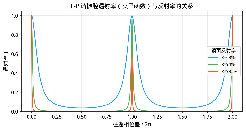
Figure 1: the transmission curve of an F–P resonator (the Airy function). The higher the reflectivity, the sharper the peaks and the higher the finesse; at 98.5% reflectivity the finesse reaches about 200.
The figure shows several things clearly:
- The higher the reflectivity, the sharper the transmission peak and the stronger the frequency selectivity
- Peak transmission can approach 100% in theory, when there is no absorption loss
- The spacing between peaks (the FSR) is uniform and set by the cavity length
- Transmission at the trough is very low, which is where the high contrast of an F–P comes from
2.3 The resonance condition
When the round-trip phase difference δ equals an integer multiple of 2π, transmission peaks. The resonance condition is:
2nLcosθ = mλ (m an integer, the order of interference)
where n is the refractive index inside the cavity, L the cavity length and θ the internal angle (cosθ = 1 at normal incidence). The resonant wavelength therefore depends on cavity length and angle — which is exactly why tilting an etalon tunes its transmission wavelength.
3. The Core Parameters in Detail
The performance of an F–P resonator is set by the parameters below, each with a clear physical meaning and formula.
3.1 Free spectral range (FSR)
The free spectral range (FSR) is the frequency or wavelength spacing between adjacent transmission peaks. It represents the largest spectral span an F–P device can measure unambiguously — if the input spectrum is wider than the FSR, peaks of different orders overlap and orders become confused.
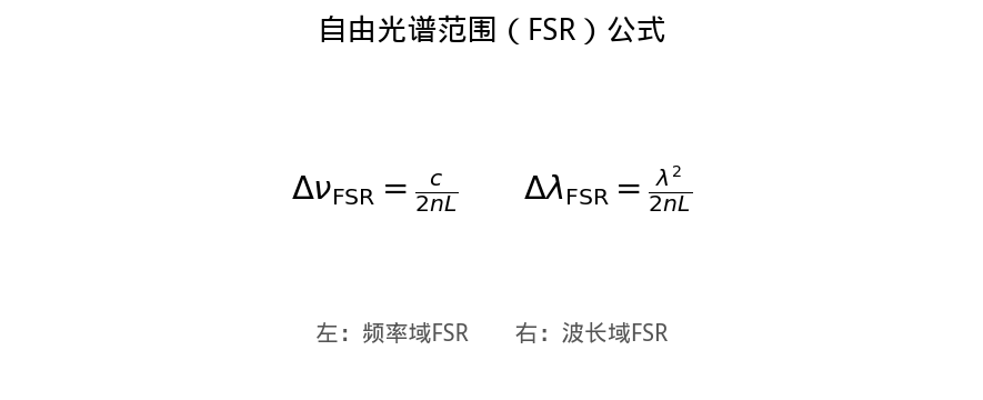
Figure 2: the FSR formulas in the frequency and wavelength domains
FSR is inversely proportional to cavity length: a longer cavity gives a smaller FSR, finer resolution of spectral lines, but a smaller unambiguous range. This is the most basic trade-off in F–P design: you cannot have both resolution and range.
3.2 Finesse (ℱ)
Finesse is the ratio of the FSR to the full width at half maximum of the transmission peak, a measure of frequency selectivity, or spectral resolution.
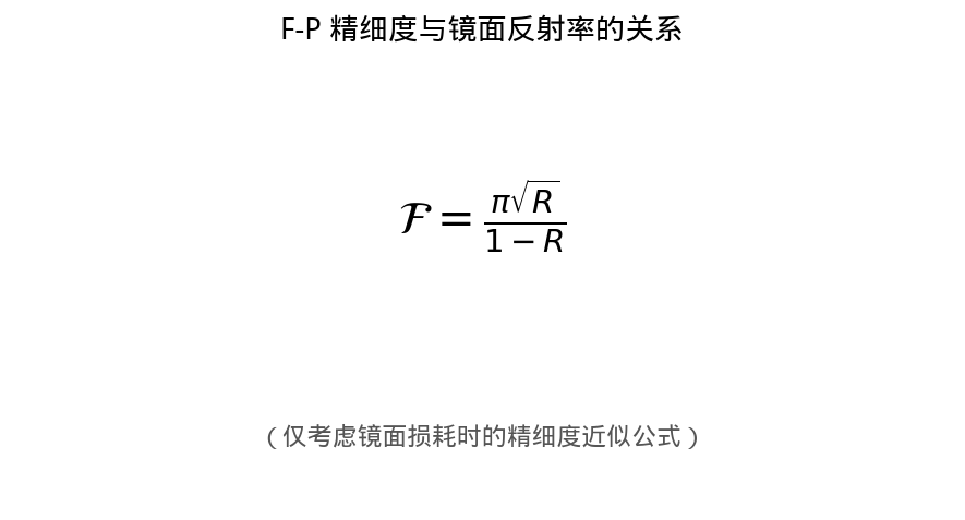
Figure 3: finesse against mirror reflectivity when mirror loss is the only loss. The higher the reflectivity, the higher the finesse.
The approximation ℱ ≈ π√R/(1−R) holds only in the ideal case of mirror transmission loss alone. A real device also has mirror absorption, scattering, surface figure errors and parallelism errors. The combined finesse is estimated from:
1/ℱ² = 1/ℱR² + 1/ℱdefect² + 1/ℱangle² + …
where ℱR is the reflectivity-limited finesse, ℱdefect the defect-limited finesse and ℱangle the finesse limited by input divergence. The total is the reciprocal root of the sum of reciprocals squared — in other words the worst term sets the total finesse.
Typical finesse values: 10–30 for an ordinary solid etalon, 100–300 for a high-finesse air-spaced etalon, and over 1000 for a confocal spherical F–P interferometer.
3.3 Resolving power
Resolving power is another common measure of spectral resolution, defined as the ratio of the centre wavelength to the smallest resolvable wavelength difference.
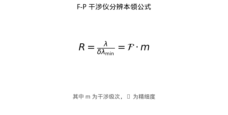
Figure 4: the resolving-power formula for an F–P interferometer. Resolving power equals finesse multiplied by the order of interference m.
Resolving power R = ℱ × m, where m = 2nL/λ is the order. A longer cavity raises the order and the resolving power — but it also lowers the FSR, since FSR = λ/m. So high resolving power is bought by shrinking the measurement range.
3.4 Peak transmission and contrast
Peak transmission is the maximum fraction transmitted at resonance. In the ideal case with no absorption and equal mirror reflectivities it reaches 100%; in practice mirror absorption and scattering always pull it below.
Contrast is the ratio of peak to trough transmission, a measure of how clean the filtering is. The higher the contrast, the better the background rejection; a higher-finesse F–P usually has higher contrast too.
| Parameter | Formula or definition | Determined by | Typical value |
|---|---|---|---|
| FSR (frequency domain) | Δν = c/(2nL) | Cavity length, refractive index | 1GHz ~ 10THz |
| Finesse ℱ | FSR / linewidth | Reflectivity, defects, divergence | 10 ~ 1000+ |
| Resolving power R | λ/δλ = ℱ × m | Finesse × cavity length / wavelength | 10⁴ ~ 10⁷ |
| Peak transmission | Maximum transmission at resonance | Absorption loss, mirror matching | 30% ~ 95% |
| Contrast | Peak / trough transmission | Finesse | 100:1 ~ 10⁶:1 |
4. Types of F–P Resonator
By construction and mode of operation, F–P resonators and interferometers fall into the following groups:
4.1 Solid etalon
The simplest F–P structure: a transparent plate polished flat and parallel on both faces and coated (usually silica, glass or a crystal). Compact and cheap, but the finesse is limited by material homogeneity and surface quality. Commonly used for intracavity mode selection and simple wavelength selection.
4.2 Air-spaced F–P interferometer
Two independent mirrors with air (or vacuum) between them. The great advantage is very low absorption loss, since there is no medium to absorb, which allows high finesse; and the spacing can be tuned, giving wavelength tuning. The drawbacks are complexity — a precision mechanism such as a piezoelectric actuator — and the need for temperature control.
4.3 Confocal spherical F–P interferometer
Two spherical mirrors with radius equal to the spacing (confocal configuration). Its great advantage is a large alignment tolerance: the input can deviate somewhat from the axis and the finesse stays high, so a larger input aperture can be used and more light collected. Confocal F–P interferometers are used for high-resolution spectroscopy and reach finesse above 1000.
4.4 Fibre F–P cavity
Fibre Bragg gratings (FBG) serve as the mirrors with a length of fibre as the cavity. Small and easily integrated into fibre systems, fibre F–P cavities are widely used in fibre sensing (temperature, strain, pressure) and in fibre lasers.
4.5 Micro-resonators
F–P resonators at the micrometre or nanometre scale — microdisc, microsphere and microring cavities. The Q factor is extremely high (above 10⁸), and they serve integrated photonics, nonlinear optics and high-sensitivity sensing.
5. Applications
F–P resonators are everywhere, from the frequency-selective element inside a laser to the heart of a precision instrument. These are the typical directions:
5.1 Single-longitudinal-mode selection in lasers
One of the commonest uses of an F–P etalon. Insert a thin etalon inside the laser cavity: its FSR is far wider than the gain bandwidth, because the etalon is thin, while its finesse is high enough, so only one longitudinal mode survives across the whole gain band and single-frequency output results. Tilting the etalon fine-tunes the selected wavelength.
5.2 High-resolution spectral analysis
The F–P interferometer is a classic high-resolution instrument. Scanning the cavity length with a piezoelectric actuator measures the spectrum point by point, with resolution above 10⁷ — far beyond a grating spectrometer. It is used for laser linewidth measurement, atomic and molecular spectroscopy, and astronomical observation.
5.3 Optical frequency reference and wavelength locking
A high-finesse, high-stability F–P reference cavity serves as a frequency standard: locking a laser to one of its resonance peaks greatly improves frequency stability. Ultra-stable cavities (ultra-low-expansion glass in vacuum) reach stabilities of order 10⁻¹⁵ and are the core component of optical atomic clocks.
5.4 Cavity ring-down spectroscopy (CRDS)
This uses the photon lifetime of an F–P cavity to measure loss inside it: inject a pulse and measure the time for the intensity to fall to 1/e. The longer the ring-down time, the lower the loss. By measuring the absorption added by a sample gas, trace concentrations can be detected down to the ppb or even ppt level.
5.5 Enhancement cavities and nonlinear optics
Coupling light into a high-finesse F–P cavity raises the intracavity power tens or hundreds of times above the incident power, the resonant enhancement effect. That high circulating power drives doubling, optical parametric oscillation and other nonlinear processes efficiently, which is particularly useful with low-power single-frequency lasers.
5.6 Wavelength-division multiplexing in communications
In dense wavelength-division multiplexed (DWDM) systems, miniature F–P filters — fibre F–P cavities, silicon microring resonators — select individual channel wavelengths and perform the add/drop multiplexing (ADM) function.
6. Common Misconceptions
Misconception 1: The higher the reflectivity, the smaller the FSR
Wrong. The FSR is set only by cavity length and refractive index (FSR = c/(2nL)) and has nothing to do with reflectivity. Reflectivity affects finesse: the higher it is, the narrower the transmission peak and the higher the finesse.
Misconception 2: F–P devices are only for laser oscillation
Wrong. The F–P structure does far more than laser cavities. The passive F–P etalon is one of the most used narrowband optical filters, appearing in spectral analysis, wavemeters, telecommunications filtering and cavity ring-down spectroscopy.
Misconception 3: Two parallel high reflectors are enough to give resonance
Not enough. Beyond an extremely tight parallelism requirement (of order arcseconds), the resonance condition must be met (cavity length an integer multiple of a half wavelength) and the loss must be low enough. If the loss is too high the light dies away after a few round trips and no clear resonance peak forms, because the finesse is very low.
Misconception 4: Finesse depends only on reflectivity
Wrong. Reflectivity is one contributor. Surface figure, parallelism, the divergence of the input beam and absorption and scattering inside the cavity all limit the finesse. The total is set by the worst of them — a barrel with a short stave.
Misconception 5: The higher the resolving power, the better
Not necessarily. Higher resolving power means a smaller FSR, hence a longer cavity and a narrower unambiguous range. The application has to weigh resolution against range. High-resolution spectrometers are usually paired with a pre-filter such as a grating monochromator to resolve the order confusion.
Misconception 6: An F–P etalon and a laser cavity are the same thing
Similar in structure, different in function. An F–P etalon is normally a passive device working in transmission, used for filtering or spectral analysis; a laser cavity contains a gain medium and works in oscillation, producing laser light. The theory behind both — multi-beam interference and the resonance condition — is the same, but the design goals and the parameters to optimise are entirely different.
Leave a Reply