


DFB Laser Encyclopedia v2 – nine-section edition
post 25728 | category 5377 | slug: dfb-laser-encyclopedia

DFB Laser Encyclopedia: Distributed Feedback Laser Principles, Structure and Applications Explained
The DFB laser (Distributed Feedback Laser) is a core light source in modern optical communications, gas detection and precision spectroscopy, playing an irreplaceable role especially in the 400G/800G/1.6T optical modules driven by AI compute. By integrating a Bragg grating inside the semiconductor chip it achieves stable single-longitudinal-mode output. The linewidth of ordinary commercial communication DFB lasers is on the MHz scale (typically 1–10 MHz); kHz or sub-kHz linewidths are limited to narrow-linewidth-optimised types (e.g. long cavity, multiple phase shifts, CPM grating designs) or hybrid external-cavity structures. Starting from the physics of DFB lasers, this article covers manufacturing processes, material/wavelength families, key parameters, spatial hole burning, reliability and the industry landscape, and provides directly usable selection comparisons and corrections of 12 common misconceptions.
============ Section 1 ============
1. Definition of Terms and Basic Concepts
The DFB laser (Distributed Feedback Laser) — distributed feedback laser — is a semiconductor laser whose entire resonator is formed by a periodic Bragg grating distributed throughout the gain medium, achieving wavelength selection and single-longitudinal-mode operation through Bragg reflection. Unlike an FP laser, which relies on facet reflections to form its cavity (an FP laser has a spectral envelope tens of nanometres wide with no single-longitudinal-mode linewidth to speak of), the DFB’s ‘feedback’ is distributed throughout the active region.
1.1 Distinguishing Easily Confused Laser Types
| Laser type | English abbreviation | Wavelength-selection mechanism | Output mode | Typical linewidth |
|---|---|---|---|---|
| Fabry–Pérot laser | FP | facet mirrors forming an FP cavity | multiple longitudinal modes (spectral envelope tens of nm) | not applicable (no single longitudinal mode linewidth) |
| Distributed feedback laser | DFB | distributed feedback from a Bragg grating inside the active region | single longitudinal mode | 1–10 MHz (ordinary commercial) |
| Distributed Bragg reflector laser | DBR | grating outside the active region (no gain region) | single longitudinal mode | 100 kHz–5 MHz |
| Electro-absorption modulated laser | EML | DFB + EAM monolithic integration | single longitudinal mode | 100 kHz–1 MHz |
| Vertical-cavity surface-emitting laser | VCSEL | DBR mirrors forming a vertical resonator | single longitudinal mode (short cavity) | hundreds of MHz–GHz |
The core difference between DFB and DBR: in a DFB the grating runs through the whole active region (gain and feedback integrated), while in a DBR the grating sits in the passive regions at either end of the active region (gain and feedback separated). DFB is more compact; DBR has a wider tuning range.
1.2 Light-Source Comparison in AI Optical Module Scenarios
| Application scenario | Data rate | Preferred light source | Reason |
|---|---|---|---|
| Short-reach DR4/FR4 | 400G (4×100G PAM4) | CWDM DFB + EAM / EML | CWDM 4-wavelength coverage, moderate cost |
| Medium-reach FR4/LR4 | 800G (8×100G PAM4) | CWDM/LAN-WDM DFB + EML | 8-wavelength multiplexing, requires narrow linewidth and low chirp |
| Long-reach ER4/ZR | 800G/1.6T | EML / coherent DFB | long reach requires ultra-low chirp and extremely narrow linewidth |
| SR short reach (within rack) | 100G/200G | VCSEL (multimode) / DFB (single mode) | VCSEL is low-cost; single-mode scenarios still use DFB |
============ Section 2 ============
2. Physical Principles
2.1 Bragg Grating Wavelength-Selection Principle
The heart of a DFB laser is the Bragg grating integrated in the active region. The grating period Λ determines the centre wavelength of the reflection peak — when the Bragg condition is satisfied, light of a particular wavelength is strongly reflected while other wavelengths pass almost unaffected.
Bragg wavelength formula:
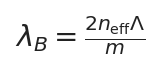
n_eff is the effective refractive index of the active region, Λ the grating period, m the diffraction order (DFB commonly uses first-order m=1).
For a first-order grating (m=1), the DFB centre wavelength is λ_B = 2·n_eff·Λ. Taking a 1550 nm InP-based DFB as an example, n_eff ≈ 3.2 gives Λ ≈ 242 nm — a precision achievable only by electron-beam lithography.
2.2 Coupling Coefficient and Grating Strength
The feedback strength of the grating is described by the coupling coefficient κ, reflecting the proportion of an optical wave coupled back into the counter-propagating mode within one grating period:
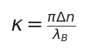
Δn is the refractive-index modulation amplitude, reflecting the grating etch depth or the strength of carrier-injection modulation.
The κL value (κ times grating length L) determines a DFB’s spectral characteristics: κL < 1 gives insufficient feedback and excessive threshold; κL ≈ 1–2 is optimal; κL > 3 gives too narrow a spectrum with reduced tuning range. In engineering κL is usually designed between 1.5 and 2.5.
2.3 λ/4 Phase-Shift Structure — Why a DFB Must Have a Phase Shift
The Bragg reflection band of a uniform grating (no phase shift) contains a ‘stopband’, with the centre exactly at the band edge and two degenerate modes symmetrically on either side — the DFB laser cannot determine on which side to oscillate, resulting in two-mode oscillation, severely reducing SMSR.
The solution is to introduce a λ/4 phase shift in the middle of the grating (an abrupt λ/4 change in grating path length), breaking the symmetry. The phase shift creates a defect mode at the centre of the stopband, located exactly at the middle of the Bragg reflection band with the lowest threshold gain, thereby ensuring stable single-longitudinal-mode oscillation. This is the standard design of all high-performance telecom DFB lasers.
2.4 Schawlow–Townes Linewidth
The linewidth of a DFB laser is described by the modified Schawlow–Townes equation:
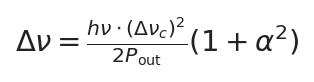
α is the linewidth enhancement factor (Henry factor); for DFB semiconductor lasers α = 2–6, making the actual linewidth 5–37 times the base value.
Here Δν_c is the photon cavity decay rate (the cold-cavity linewidth) and P_out the output optical power. Key conclusions:
- higher output power → narrower linewidth (but not a linear relationship)
- the α factor is the main cause of linewidth ‘degradation’ in semiconductor lasers — a DFB’s α is an order of magnitude larger than a fibre laser’s
- ordinary commercial 1550 nm communication DFB linewidth 1–5 MHz; high-quality narrow-linewidth DFB (multi-phase-shift/CPM design) can reach the 100 kHz level; hybrid external-cavity schemes can go below kHz
2.5 Index Coupling vs Gain Coupling
DFB grating feedback mechanisms fall into two basic types:
| Characteristic | Index Coupled | Gain Coupled |
|---|---|---|
| Feedback mechanism | periodic refractive-index modulation Δn | periodic gain/loss modulation Δg |
| Implementation | etched grooves or periodic variation of ridge waveguide | periodic absorption layer or carrier-injection modulation |
| Threshold gain difference | two degenerate modes have equal threshold (phase shift needed to break degeneracy) | the main mode naturally has the lowest threshold (no λ/4 phase shift needed) |
| Spatial hole burning | sensitive — SHB reduces mode discrimination | inherently immune — SHB does not affect gain-coupling selectivity |
| Process difficulty | relatively simple, mainstream approach | requires precise control of the absorption layer, complex process |
| Typical application | the vast majority of commercial DFBs | high-power and special applications demanding high SMSR |
In real products, index-coupled DFBs account for over 90% of the market. The advantage of gain-coupled DFBs is single-mode operation without a phase shift and inherent immunity to spatial hole burning (see Section 4.4).
2.6 SMSR (Side-Mode Suppression Ratio)
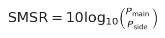
P_main is the main-mode power and P_side the strongest side-mode power; a typical DFB value is ≥40 dB, meaning the side mode is 10,000 times weaker than the main mode.
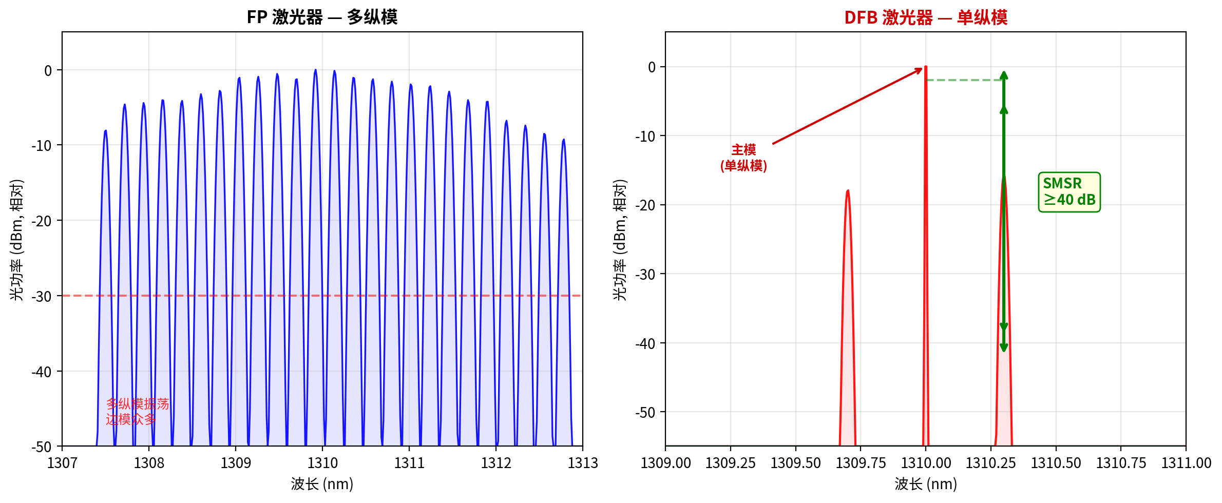
DFB single-longitudinal-mode spectrum vs FP multi-longitudinal-mode spectrum, with SMSR marked. Source: drawn by the Changsha Soar Laser technical team
SMSR ≥ 40 dB means the strongest side mode has only one ten-thousandth the power of the main mode. For coherent optical communication local-oscillator (LO) applications, SMSR ≥ 50 dB is required — a stringent specification, because side modes contribute directly to phase noise and channel crosstalk. ITU-T G.959.1 requires DFB sources to have SMSR ≥ 35 dB (minimum), while real products usually achieve ≥40 dB.
============ Section 3 (added) ============
3. Manufacturing Process
DFB laser fabrication is among the most precise processes in semiconductor optoelectronics. Taking an InP-based 1550 nm BH (buried heterostructure) DFB as an example, the core flow includes 8 key steps:
| Step | Process name | Key content | Difficulty / notes |
|---|---|---|---|
| ① | Epitaxial growth (MOVPE) | grow n-cladding, grating layer (to become the Bragg grating after etching) on an InP substrate | thickness precision <1 nm, determining wavelength accuracy |
| ② | Grating etching | electron-beam lithography (EBL) or holographic lithography defines a ~240 nm period; dry/wet etching forms grooves | ⚠️ EBL is costly but most precise; nanometre-scale period uniformity required |
| ③ | λ/4 phase-shift introduction | create a λ/4 path-length discontinuity in the middle of the grating (locally removing or shifting half a period) | phase-shift accuracy directly determines SMSR |
| ④ | Regrowth | MOVPE regrowth: cover grating layer → lower cladding → multiple-quantum-well active region → upper cladding → contact layer | ⚠️ the greatest barrier: the regrowth interface must be atomically clean or it introduces scattering loss and non-radiative recombination |
| ⑤ | Ridge/mesa etching | define the lateral waveguide structure (ridge waveguide) or prepare the mesa for a BH structure | sidewall roughness affects scattering loss |
| ⑥ | BH buried regrowth (BH type) | second MOVPE regrowth of InP burying layer surrounding the active region for dual confinement of current and optical field | ⚠️ second-regrowth barrier: interface quality and doping profile must be precisely controlled |
| ⑦ | Cleavage and coating | cleave along crystal planes to form facets; apply anti-reflection (AR) coating to prevent facet reflection interfering with DFB mode selection | AR coating reflectance must be <0.1% or single-mode stability is disrupted |
| ⑧ | Packaging and testing | die attach → wire bonding → TEC integration → fibre coupling → P-I-V test → spectral test → burn-in screening | butterfly package includes TEC + thermistor + back-facet monitor PD + isolator |
Core barrier — the regrowth process: a BH-type DFB needs two MOVPE regrowth steps (covering over the grating + burying the sides of the active region). Each regrowth requires an atomically clean interface and precise doping transitions. Regrowth quality directly determines threshold current, slope efficiency and reliability. Fewer than 20 companies worldwide can volume-produce high-quality BH DFBs consistently.
============ Section 4 (added) ============
4. Material Systems and Wavelength Families
A DFB laser’s output wavelength is determined jointly by the gain medium’s bandgap and the grating period. Different material systems cover different wavelength ranges:
| Material system | Substrate | Wavelength range | Typical applications |
|---|---|---|---|
| GaAs / AlGaAs | GaAs | 760–1000 nm | rubidium atomic clock (780/795 nm), O₂ detection (760 nm), pump source (980 nm) |
| InP / InGaAsP | InP | 1100–1700 nm | optical communications (1310/1550 nm), TDLAS gas detection (1278–1854 nm) |
| InP / AlGaInAs | InP | 1200–1600 nm | high-speed directly modulated DFB (better bandwidth than InGaAsP), 50G+ PAM4 optical modules |
| GaSb / InGaAsSb | GaSb | 1900–3300 nm | mid-IR gas detection (CO₂ 2.0 μm, CO 2.3 μm, CH₄ 3.3 μm) |
| QCL (quantum cascade laser) | InP | 3.0–12 μm | mid/far-IR gas detection (N₂O 4.5 μm, NO 5.2 μm, CH₄ 7.6 μm) |
| InP-on-Si (heterogeneous silicon integration) | Si | 1310/1550 nm | silicon-photonic integrated PIC, CPO co-packaged optics |
Note: QCLs/ICLs are strictly unipolar devices (only electrons or only holes participate), physically different from conventional bipolar DFB lasers, but they likewise use distributed-feedback gratings for single-longitudinal-mode operation and are often classed as ‘DFB-type lasers’ in gas detection.
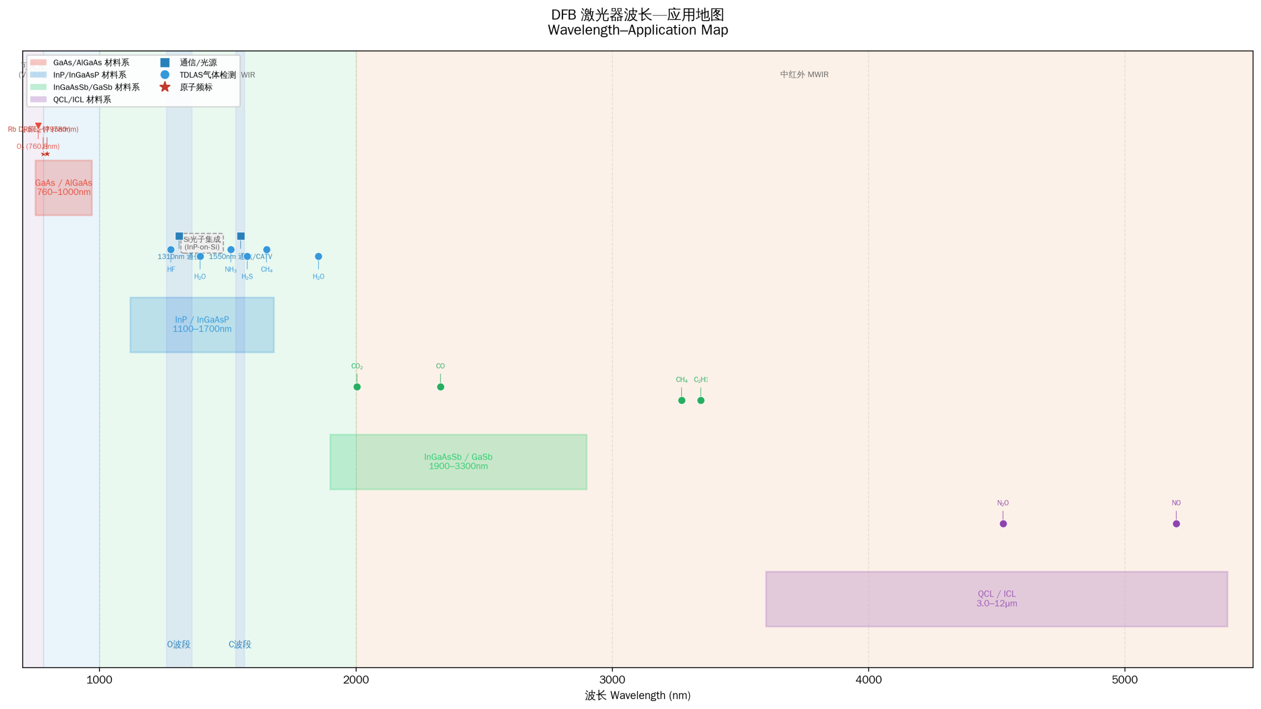
DFB laser wavelength–application map. Horizontal axis is wavelength (700–5500 nm), vertical axis divided by material system, marking major application wavelengths and gas absorption lines. Source: drawn by the Changsha Soar Laser technical team
============ Section 5 ============
5. Structure and Classification
5.1 Chip Structure
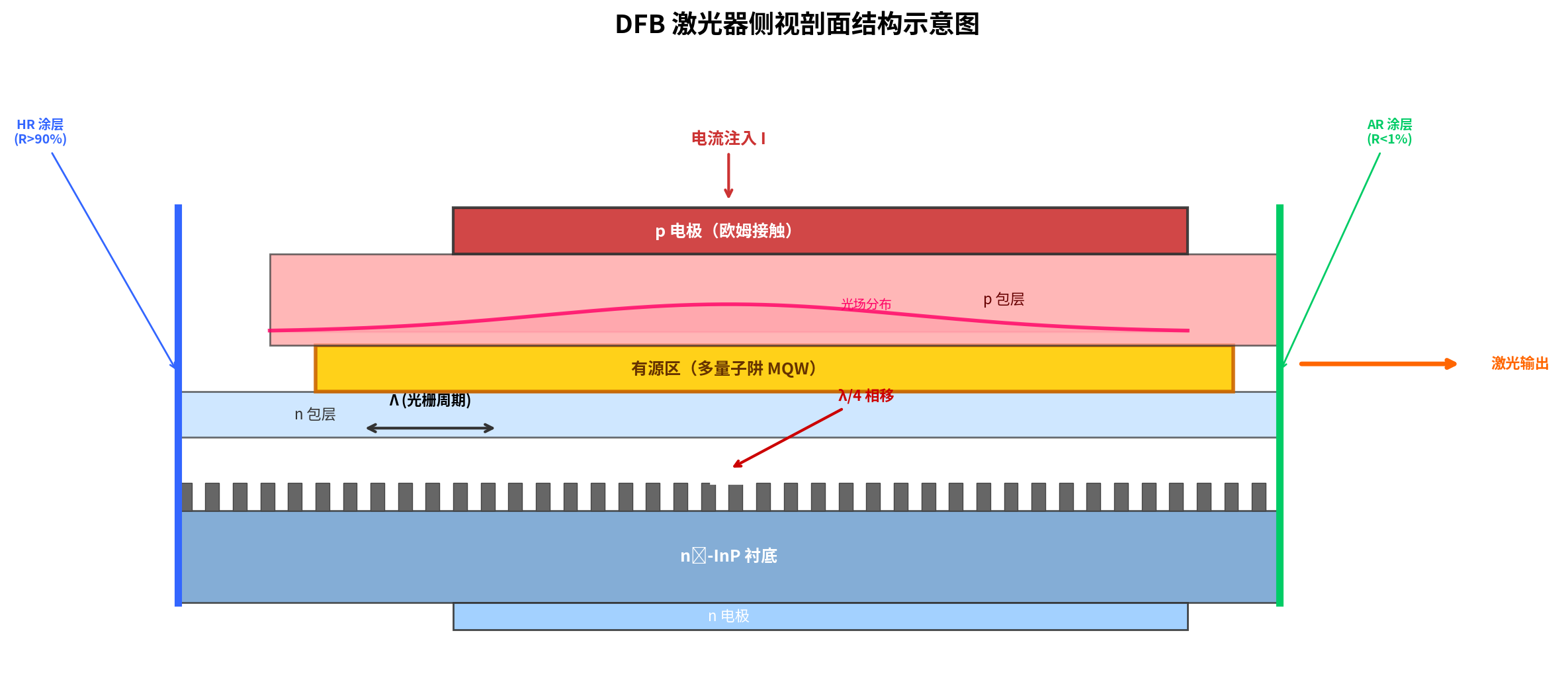
DFB laser side-view cross-section: p electrode, quantum-well active region, Bragg grating, λ/4 phase-shift location. Source: drawn by the Changsha Soar Laser technical team
The typical structure of a DFB semiconductor laser (taking an InP-based 1550 nm DFB as an example), from bottom to top, comprises:
- n-type InP substrate: mechanical support and n-side electrode contact
- Bragg grating layer (corrugated grating): periodic grooves etched in the n-cladding or above the active region
- n-type InP lower cladding: optical confinement and carrier injection
- active region (multiple quantum wells, MQW): InGaAsP/InP MQW providing gain
- p-type InP upper cladding: optical confinement
- p+ InGaAs contact layer: ohmic contact
5.2 Waveguide Types
| Structure type | Characteristic | Advantage | Disadvantage |
|---|---|---|---|
| Ridge waveguide | mesa-ridge structure confining the lateral optical field, simple process | mature process, low cost, suited to volume production | slightly higher sidewall scattering loss, average beam quality |
| Buried heterostructure (BH) | active region fully surrounded by InP burying layer, confining both lateral optical field and current | low threshold, high efficiency, good beam quality | requires a second MOVPE regrowth, high cost |
| Lateral coupling | grating on both sides of the active region, not crossing it | avoids grating-etch damage to the active region, no regrowth needed | smaller coupling coefficient κ requiring a longer grating; niche/laboratory approach, rarely adopted in volume production |
On lateral coupling: this approach avoids damage to the active region from grating etching or regrowth; κ is small but can be compensated by increasing grating length. A team at the Institute of Semiconductors, Chinese Academy of Sciences achieved SMSR 53 dB on a 2 μm GaSb-based lateral-coupling DFB. However, the approach remains largely at the academic research stage, with commercial products dominated by ridge waveguides and BH.
5.3 Package Types
| Package type | English | Characteristic | Typical application |
|---|---|---|---|
| TO-CAN coaxial | TO-56 / TO-46 | small metal can with lens window or fibre pigtail, low cost | sensing, CATV, low-speed communications |
| Butterfly | Butterfly | sealed metal housing integrating TEC + thermistor + back-monitor PD + isolator | 400G/800G optical modules, coherent systems |
| Micro coaxial with TEC | Mini-DIL with TEC | micro TEC integrated on a TO-56 base | CWDM DFB, LAN-WDM DFB |
| COB bare die | Bare Die / Chip-on-Board | unpackaged DFB chip mounted directly on a silicon-photonic/InP PIC substrate | CPO co-packaged optics, silicon-photonic integration |
5.4 Classification by Wavelength
| Band | Wavelength range | Typical use | Dispersion characteristic |
|---|---|---|---|
| O band | 1260–1360 nm (centre 1310 nm) | data-centre short/medium reach, PON upstream | zero-dispersion window, no dispersion compensation needed |
| C band | 1530–1565 nm (centre 1550 nm) | long-haul transmission, coherent communications, DWDM | lowest-loss window, dispersion must be considered |
| CWDM | 8 wavelengths (1270–1610 nm, 20 nm spacing) | 400G DR4/FR4 parallel optical modules | dispersion differs per wavelength, O band advantageous |
| LAN-WDM | 4–8 wavelengths (within O band, 4.5 nm spacing) | 800G DR8/LR8 optical modules | all within the zero-dispersion window, no DCM needed |
| L band | 1565–1625 nm | extended C+L band capacity | larger dispersion, usually needs compensation |
============ Section 6 ============
6. Key Parameters in Detail
| Parameter | Symbol | Physical meaning | Typical 1310 nm DFB value | Typical 1550 nm DFB value |
|---|---|---|---|---|
| Threshold current | I_th | minimum injection current at which the laser begins stimulated emission | 5–15 mA | 8–20 mA |
| Slope efficiency | η_d | increment of output optical power per 1 mA of current above threshold | 0.1–0.5 mW/mA | 0.1–0.4 mW/mA |
| Side-mode suppression ratio | SMSR | ratio of main-mode power to strongest side-mode power | ≥40 dB | ≥45 dB |
| Linewidth | Δν | full width at half maximum (FWHM) of the single-longitudinal-mode spectrum | 1–5 MHz | 100 kHz–5 MHz |
| Relative intensity noise | RIN | intensity fluctuation of optical power (dB/Hz) | −145 ~ −135 dB/Hz | −150 ~ −140 dB/Hz |
| Modulation bandwidth | f_3dB | −3 dB electrical bandwidth under direct modulation | 10–25 GHz | 10–30 GHz (directly modulated DFB); EML 40+ GHz |
| Chirp parameter | α | coupling coefficient of frequency change with power under direct modulation | α = 2–4 | DFB: α=2–4; EML: α≈0.5–1.5 |
| Operating temperature range | T_op | temperature range for stable operation without tuning | −5 to 75 °C (with TEC: 15–35 °C constant) | −5 to 70 °C (with TEC: 20–40 °C constant) |
Modulation bandwidth note: in the 1550 nm band, the modulation bandwidth ceiling of a directly modulated DFB is 25–30 GHz (frontier research reports up to about 30–35 GHz). Bandwidths of 40 GHz and above belong to the EML (DFB + EAM integrated) category. When selecting, strictly distinguish ‘directly modulated DFB bandwidth’ from ‘EML bandwidth’ — they must not be conflated.
6.1 P-I-V Characteristics and Modulation Eye Diagram
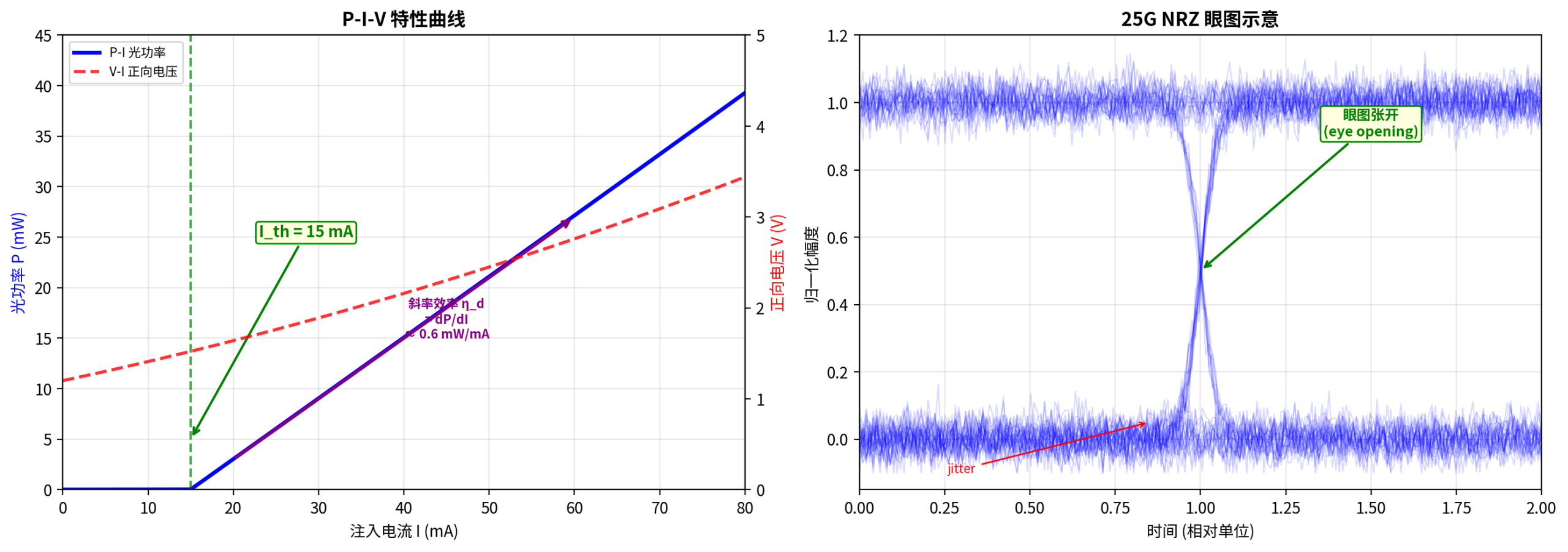
P-I-V characteristic curve (left) and a 25G NRZ eye diagram (right). Source: drawn by the Changsha Soar Laser technical team
The left figure shows the two key regions of the P-I curve: below threshold spontaneous emission dominates (very low, nonlinear power), above threshold stimulated emission takes over (power grows linearly with current). The V-I curve reflects the forward conduction voltage; InP-based DFBs typically have V_f ≈ 1.2–1.8 V.
The right figure shows a 25G NRZ eye diagram. The larger the eye opening, the better the signal quality. A DFB laser’s bandwidth, chirp and RIN jointly determine the eye opening.
6.2 Spatial Hole Burning (SHB)
Spatial hole burning is an important effect in DFB lasers operating above threshold, directly affecting single-mode stability and linewidth performance:
Physical mechanism: the forward and backward optical fields in a DFB cavity form a standing-wave pattern, causing spatially non-uniform depletion of carrier density (fast at antinodes, slow at nodes). This non-uniform carrier distribution in turn changes the local refractive index, distorting the effective period of the grating.
Consequences:
- SMSR degradation: SHB reduces the threshold-gain difference between main and side modes, so side-mode suppression worsens as power rises
- Linewidth broadening: side modes contribute extra frequency noise through mode partition noise, causing linewidth to depart from the ideal 1/P relation
- Mode-hopping risk: severe SHB at high power can cause mode hops
Suppression methods:
- Multiple phase-shift design: splitting a single λ/4 phase shift into several smaller shifts (e.g. three λ/5 shifts) to flatten the intracavity optical field distribution
- CPM grating (Corrugation-Pitch-Modulated): gradually varying the grating period in the phase-shift region rather than abruptly
- Gain-coupled DFB: the gain-coupling mechanism is inherently immune to SHB’s effect on mode discrimination (see Section 2.5)
- Reducing κL: weaker coupling (κL ≈ 1–1.5) mitigates SHB but sacrifices SMSR and wavelength stability
============ Section 7 ============
7. Characteristics: Advantages and Boundaries
7.1 Advantages
| Advantage | Description | Application scenario |
|---|---|---|
| Single-longitudinal-mode output | SMSR ≥ 40 dB, pure spectrum, no mode hopping | all scenarios needing a narrow spectrum: communications, sensing, spectroscopy |
| Narrow linewidth | ordinary commercial MHz level; optimised types 100 kHz level | coherent communications, distributed fibre sensing, spectral analysis |
| High-speed direct modulation | directly modulated DFB 25–30 GHz; EML 40+ GHz | 100G/lane optical modules (400G/800G) |
| Miniaturisation | chip size on the order of 300×300 μm², COB mountable | CPO, silicon-photonic integration, high-density optical modules |
| Selectable wavelength | precise wavelength control by designing the grating period | CWDM/LAN-WDM multiwavelength systems |
7.2 Boundaries and Limitations
| Limitation | Reason | Coping strategy |
|---|---|---|
| Temperature sensitivity | wavelength drift ~0.1 nm/°C; without temperature control, mode hopping occurs | must be equipped with a TEC temperature-control module |
| Cost higher than FP/VCSEL | grating etching/regrowth processes are complex with high yield requirements | at high volume, optical chip costs have fallen markedly |
| Direct-modulation chirp | carrier-density change → refractive-index fluctuation → frequency chirp | use EML (external modulation) or pre-chirp compensation for long reach |
| Sensitivity to optical feedback | external reflected light disrupts single-mode stability | integrate an optical isolator, use APC connectors |
| Limited direct-modulation bandwidth | directly modulated DFB ceiling ~30 GHz; 200G/lane needs external modulation | EML or DFB CW + TFLN external modulation |
============ Section 8 ============
8. Typical Applications
8.1 AI Optical Modules (400G/800G/1.6T)
AI large-model training clusters (GPU/NPU clusters) need ultra-high-bandwidth, ultra-low-latency optical interconnects. Current mainstream schemes:
| Optical module specification | Per-lane rate | Light-source scheme | DFB requirement |
|---|---|---|---|
| 400G DR4 | 4 × 100G PAM4 | 4-channel CWDM DFB | 1310 nm band, 25 GHz bandwidth |
| 400G FR4 | 4 × 100G PAM4 | 4-channel CWDM DFB + EML | 1310 nm CWDM, low chirp |
| 800G DR8 | 8 × 100G PAM4 | 8-channel LAN-WDM DFB | O band 4.5 nm spacing, 50 GHz bandwidth |
| 800G LR/ER | 8 × 100G PAM4 | C-band DFB + EML | 1550 nm, extremely low chirp |
| 1.6T DR8 | 8 × 200G PAM4 | Scheme A: DFB CW + TFLN external modulation Scheme B: EML (DFB+EAM integrated) |
Scheme A needs an ultra-narrow-linewidth CW DFB; Scheme B needs a high-bandwidth EML. The two routes are competitive: TFLN has greater bandwidth potential (>100 GHz), while EML is more mature |
1.6T route competition: the current 1.6T optical module has two mainstream light-source routes — ① DFB CW source + TFLN external modulation, with >100 GHz bandwidth potential, the long-term direction; ② EML (DFB+EAM monolithic integration), with a more mature supply chain and clear short-term volume-production advantage. The routes are not mutually exclusive and may each prevail in different transmission-distance scenarios.
8.2 TDLAS Gas Detection — Full Gas Spectral Line Table
TDLAS (Tuneable Diode Laser Absorption Spectroscopy) is the most important non-communication application of DFB lasers. By tuning the wavelength of a narrow-linewidth DFB laser to precisely align with a gas molecule’s absorption line, trace-gas detection at ppm/ppb levels is achieved.
| Target gas | DFB wavelength (nm) | Material system | Absorption band type | Typical application |
|---|---|---|---|---|
| O₂ (oxygen) | 760.8 | GaAs/AlGaAs | near-IR | combustion control, medical respiration |
| HF (hydrogen fluoride) | 1278.8 | InP/InGaAsP | near-IR overtone | semiconductor-process exhaust monitoring |
| H₂O (water vapour) | 1392 / 1854 | InP/InGaAsP | near-IR overtone | humidity measurement, combustion diagnostics |
| NH₃ (ammonia) | 1512.2 | InP/InGaAsP | near-IR overtone | SCR denitrification, environmental monitoring |
| H₂S (hydrogen sulfide) | 1560–1590 | InP/InGaAsP | near-IR overtone | natural-gas safety, petrochemical |
| CH₄ (methane) | 1651 / 1654 | InP/InGaAsP | near-IR overtone | natural-gas leakage, coal-mine safety |
| HCl (hydrogen chloride) | 1742 | InP/InGaAsP | near-IR overtone | waste incineration emissions |
| CO₂ (carbon dioxide) | 2004 / 2009(¹³C) | InGaAsSb/GaSb | mid-IR combination band | carbon-emission monitoring, greenhouse gases |
| CO (carbon monoxide) | 2330 / 2334 | InGaAsSb/GaSb | mid-IR combination band | industrial safety, combustion diagnostics |
| CH₄ (methane, strong absorption) | 3240 / 3270 | InGaAsSb/GaSb | mid-IR fundamental | high-sensitivity methane detection |
| C₂H₆ (ethane) | 3345 / 3375 | InGaAsSb/GaSb | mid-IR fundamental | natural-gas composition analysis |
| N₂O (nitrous oxide) | 4524 / 4534 | QCL | mid-IR fundamental | medical anaesthesia gas, greenhouse |
| NO (nitric oxide) | 5184 / 5263 | QCL | mid-IR fundamental | vehicle exhaust, industrial emissions |
8.3 Other Typical Applications
| Application field | Typical use | DFB requirement |
|---|---|---|
| Coherent optical communication | local-oscillator (LO) source, seed source for long-haul transmission | linewidth <100 kHz, SMSR ≥50 dB, extremely high wavelength stability |
| Optical fibre sensing | OTDR, distributed acoustic sensing (DAS), Brillouin scattering | narrow linewidth, low phase noise, high coherence |
| Atomic frequency standards | rubidium atomic clock (Rb D₂ line 780.24 nm, D₁ line 794.98 nm) | narrow linewidth, frequency locked to atomic transition lines |
| CATV / cable television | optical transmitter source (1550 nm AM-VSB) | low RIN, high linearity, wide dynamic range |
| Pump source | erbium-doped fibre amplifier (EDFA) pumping (980 nm/1480 nm) | high power, high reliability |
| Medical OCT | optical coherence tomography source | broadband tuneable or swept DFB |
8.4 Reliability Standards
DFB laser reliability is governed by the Telcordia GR-468-CORE standard; key metrics:
| Reliability parameter | Requirement | Description |
|---|---|---|
| FIT rate (failures in time) | < 1 FIT (≤1 failure per 10⁹ device-hours) | baseline reliability metric for telecom-grade DFBs |
| Operating lifetime | ≥25 years (~220,000 hours) | under rated operating conditions (25 °C, rated current) |
| COD threshold (Catastrophic Optical Damage) | > 10 MW/cm² (facet power density) | AR coating quality directly affects the COD threshold |
| Ageing test | 85 °C / 85% RH / 1000 h (THB) | accelerated high-temperature/high-humidity ageing verifying package hermeticity |
| Temperature cycling | −40 °C to +85 °C, 500 cycles | verifying reliability under thermomechanical stress |
============ Section 9 ============
9. History and Development Trends
9.1 Technology Evolution Timeline
| Year | Milestone | Significance |
|---|---|---|
| 1971 | Kogelnik & Shank first demonstrated the DFB concept in a dye laser (Appl. Phys. Lett. 18, 152) | first experimental proof that distributed feedback can produce laser oscillation |
| 1972 | Kogelnik & Shank published coupled-wave theory (J. Appl. Phys. 43, 2327) | established the complete theoretical foundation of DFB lasers |
| 1973 | Nakamura et al. (Caltech) achieved optically pumped DFB lasing in GaAs | first transfer of the DFB concept to semiconductor materials |
| 1975 | Scifres et al. achieved electrically pumped GaAs DFB lasers | first electrically injected semiconductor DFB, laying the foundation for practical use |
| 1982 | λ/4 phase-shift DFB realised (Utaka et al.) | solved the two-mode oscillation problem, achieving true single longitudinal mode |
| 1990s | DFB became the telecom standard light source (STM-16/64) | replaced FP as the mainstay of long-haul communications |
| 2000s | EML (DFB+EAM) commercialised | overcame the chirp limit, enabling 40G long reach |
| 2010s | CWDM DFB + silicon-photonic integration emerged | 100G/400G data-centre optical interconnects |
| 2020s | 800G/1.6T drives 100G/lane+ DFB + TFLN | high-bandwidth DFB + TFLN external modulation + CPO |
9.2 Future Trends
① Higher-bandwidth DFB chips: to support 200G/lane (100 GBaud PAM4), DFB modulation bandwidth must exceed 50 GHz. Frontier work focuses on optimising quantum-well design and shortening photon lifetime.
② Thin-film lithium niobate (TFLN) + DFB scheme: TFLN modulators exceed 100 GHz bandwidth and, paired with a narrow-linewidth DFB source, are a candidate for 1.6T optical modules. The DFB only supplies stable CW light; modulation is done by the TFLN.
③ CPO co-packaged optics: bare DFB dies are integrated directly inside the switch-chip package, shortening the electrical path and reducing power. This places extreme demands on DFB thermal management (the TEC must suit the CPO thermal environment).
④ Heterogeneous silicon integration: InP DFBs are integrated onto silicon-photonic platforms by wafer bonding or micro-transfer-printing, enabling large-scale photonic integrated circuits (PIC).
============ Industry Landscape ============
10. Industry Landscape and Market Overview
The global DFB laser market is dominated by manufacturers in Japan, the United States and China. By application it splits into two camps: communication DFBs (optical-module sources) and sensing DFBs (TDLAS gas detection):
| Manufacturer | Country / region | Core products | Main market |
|---|---|---|---|
| Lumentum | United States | high-speed EML, CWDM DFB | 400G/800G optical modules |
| Mitsubishi Electric | Japan | 1.3 μm/1.55 μm DFB, EML | telecom, data centres |
| Sumitomo Electric | Japan | EA-DFB, high-speed directly modulated DFB | telecom, CATV |
| II-VI (Coherent) | United States | DFB, EML, pump lasers | communications, industrial |
| nanoplus | Germany | full-wavelength TDLAS DFB (760–5300 nm) | gas detection, spectroscopy |
| Thorlabs | United States | research-grade DFB (1310/1368/1550 nm) | research, sensing |
| Yuanjie Technology (Source Photonics/Accelink-related Chinese vendor) | China | 2.5G–50G DFB/EML chips | localisation of optical-module chips |
| Wuhan Minxin | China | DFB/EML chips | 5G fronthaul, data centres |
In market size, the global DFB laser market (including EML) was estimated at about US$3–4 billion in 2024, driven by AI data-centre demand for 800G/1.6T optical modules and expected to exceed US$8 billion by 2030. Chinese manufacturers have progressed rapidly in localising communication DFB chips, but high-end EML and narrow-linewidth DFBs remain dominated by Japanese and American vendors.
============ Selection ============
11. Selection Advice
11.1 Wavelength Selection
| Selection scenario | Recommended wavelength | Reason |
|---|---|---|
| Data centre ≤2 km | O band (1310 nm / CWDM / LAN-WDM) | zero dispersion, no DCM needed, low cost |
| Metro network 2–40 km | C band (1550 nm) | lowest loss + EDFA amplification support |
| Long/ultra-long haul >40 km | C-band EML or coherent DFB | extremely low chirp + narrow linewidth + amplifier |
| Gas detection | gas absorption-line wavelength (see Section 8 table) | narrow-linewidth tuneable, aligned to absorption peak |
11.2 Modulation Format Selection
| Modulation format | Per-lane rate | Light-source requirement | DFB choice |
|---|---|---|---|
| NRZ | 10G / 25G | bandwidth ≥18 GHz | directly modulated DFB |
| PAM4 | 50G / 100G | bandwidth ≥25 GHz, low chirp | EML primary / high-bandwidth DFB |
| coherent (DP-QPSK/16QAM) | 100G–800G/lane | linewidth <100 kHz | external-cavity DFB / narrow-linewidth EML |
11.3 Package Selection Advice
- TO-CAN: cost-sensitive, stable temperature environment, rates ≤25G (CATV, sensing, PON)
- Butterfly: high-speed optical modules (100G+), applications needing precise TEC control, integrating isolator and back-monitor PD
- COB bare die: CPO co-packaged optics and silicon-photonic integration, DFB chip mounted directly on the silicon-photonic substrate
============ Common Misconceptions ============
12. Correction of 12 Common Misconceptions
| No. | Misconception | Correct understanding |
|---|---|---|
| 1 | ‘A DFB is a single-mode fibre laser’ | ❌ A DFB is a feedback mechanism inside a laser chip, not a fibre laser. The most common DFB is a semiconductor laser diode. DFB structures also exist in fibre (a fibre Bragg grating written into doped fibre), but that is a different device. ‘Single mode’ refers to a single longitudinal output mode, a different concept from ‘single-mode fibre’. |
| 2 | ‘A DFB needs no temperature control’ | ❌ A DFB’s wavelength drifts about 0.1 nm/°C. An uncontrolled 1310 nm DFB drifts 2.5 nm over a 25 °C change, enough to leave a CWDM channel spacing. In high-speed optical modules a DFB must have a TEC holding temperature within ±0.1 °C. |
| 3 | ‘A DFB is cheaper than a VCSEL’ | ❌ In short-reach multimode scenarios (SR), VCSELs cost far less than DFBs. VCSEL wafer-level testing and surface-emission processing are simple. A DFB needs grating etching + cleavage + back-monitor + TEC, making it costlier overall. A DFB’s advantage is single-mode long-reach capability, not cost. |
| 4 | ‘The narrower the linewidth, the better’ | ❌ Narrow linewidth matters for coherent communications and sensing, but for directly modulated optical modules (NRZ/PAM4) there is no significant performance difference between 1 MHz and 5 MHz linewidth. Pursuing ultra-narrow linewidth increases design complexity and cost. Select according to real requirements. |
| 5 | ‘A DFB can be directly modulated to 100G’ | ❌ 100G/lane needs about 50 GHz modulation bandwidth, while a directly modulated DFB tops out at 25–30 GHz. The industry mainstream is EML (DFB + EAM integrated) or a DFB CW source + TFLN external modulation. |
| 6 | ‘1310 nm needs no dispersion compensation so it can be used anywhere’ | ❌ It is true that the O band has near-zero dispersion in standard single-mode fibre. But a DFB’s chirp (α parameter) still causes chirp broadening, especially when directly modulating high-speed signals. 1310 nm links beyond 40 km also need chirp-penalty assessment. |
| 7 | ‘DFB and DBR are the same thing’ | ❌ Both use Bragg gratings for wavelength selection, but the grating location differs: a DFB grating runs through the active region (gain and feedback integrated), while a DBR grating sits in the passive section outside the active region (gain and feedback separated). DBR has a wider tuning range (~10 nm), DFB is more compact. |
| 8 | ‘A DFB needs no isolator’ | ❌ A DFB is extremely sensitive to external optical feedback (return light above −40 dB can disrupt single-mode stability). Butterfly packages usually integrate an isolator; with TO-CAN packages, add an isolator in the external path or use APC connectors. |
| 9 | ‘SMSR 40 dB and 50 dB make no difference’ | ❌ SMSR 40 dB means the side mode has one ten-thousandth the main-mode power, 50 dB one hundred-thousandth — a tenfold difference. In coherent systems (16QAM/64QAM) side modes contribute directly to phase noise and channel crosstalk. SMSR ≥ 50 dB is a stringent specification for coherent local oscillators (LO), not required of ordinary communication DFBs. |
| 10 | ‘DFBs are only used in communications’ | ❌ DFBs are also widely used in TDLAS gas detection (narrow linewidth aligned to gas absorption lines), distributed fibre sensing (DAS/DTS), spectral analysis, atomic frequency standards (rubidium clocks) and medical OCT. Communications is simply the largest market. |
| 11 | ‘694 nm DFB is used for rubidium atomic clocks’ | ❌ 694 nm is the laser wavelength of ruby (Cr:Al₂O₃) and has nothing to do with rubidium clocks. Rubidium clocks use DFB/DBR lasers at 780.24 nm (Rb D₂ line) and 794.98 nm (Rb D₁ line). These are two entirely different physical systems. |
| 12 | ‘The FP version of a DFB has a linewidth of tens of nm’ | ❌ Incorrect phrasing. An FP laser is not ‘a DFB with a wide linewidth’ — FP and DFB are completely different resonator mechanisms. An FP laser’s spectral envelope is indeed tens of nanometres wide (containing multiple longitudinal modes), but it has no single-longitudinal-mode linewidth concept because multiple modes oscillate simultaneously. The FP spectral width should not be called a ‘linewidth’. |
============ Further Reading ============
Further reading
- Achromatic f-theta lens encyclopedia — the role of f-theta lenses in laser scanning systems
- Protection window encyclopedia — selection of protection windows for laser systems
- Dichroic mirror encyclopedia — core splitting elements in wavelength division multiplexing
- Polarisation rotator encyclopedia — polarisation control and polarisation-maintaining systems
- Aperture encyclopedia — beam aperture management and stray-light control
- Telecentric achromatic f-theta lens encyclopedia — high-precision laser processing lenses
============ References ============
References
- H. Kogelnik & C.V. Shank, ‘Stimulated emission in a periodic structure,’ Appl. Phys. Lett., vol. 18, pp. 152–154, 1971.
- H. Kogelnik & C.V. Shank, ‘Coupled-wave theory of distributed feedback lasers,’ J. Appl. Phys., vol. 43, pp. 2327–2335, 1972.
- M. Nakamura et al., ‘Laser oscillation in a periodic structure,’ Appl. Phys. Lett., vol. 23, p. 224, 1973.
- D.R. Scifres et al., ‘Double heterostructure GaAs distributed feedback laser,’ Appl. Phys. Lett., vol. 25, p. 200, 1974.
- S. Utaka et al., ‘λ/4-shifted InGaAsP/InP DFB lasers for 1.3 μm band,’ Electron. Lett., vol. 18, pp. 592–594, 1982.
- RP Photonics, ‘Distributed Feedback Lasers,’ https://www.rp-photonics.com/distributed_feedback_lasers.html
- L.A. Coldren, S.W. Corzine, M.L. Mashanovitch, Diode Lasers and Photonic Integrated Circuits, 2nd Ed., Wiley, 2012.
- ITU-T G.959.1, ‘Optical transport network physical layer interfaces,’ 2024.
- IEEE 802.3ck/dq, ‘Amendment: PMD and associated sublayers for 100G/lane and 200G/lane,’ 2024–2025.
- Telcordia GR-468-CORE, ‘Reliability Assurance Requirements for Optoelectronic Devices Used in Telecommunications Equipment.’
- B. Borchert et al., ‘Spatial Hole Burning Effects in Distributed Feedback Semiconductor Lasers,’ IEEE, 1992.
- nanoplus, ‘Distributed Feedback Lasers (DFB): Top Wavelengths,’ product datasheet, 2023.
============ Glossary ============
Glossary
| Term | English | Meaning |
|---|---|---|
| Bragg grating | Bragg Grating | periodic refractive-index/gain modulation structure providing wavelength-selective feedback |
| Side-mode suppression ratio | SMSR | power ratio of the main mode to the strongest side mode (dB), measuring single-mode purity |
| Linewidth enhancement factor | α (Henry factor) | ratio of refractive-index change to gain change caused by carrier-density variation in semiconductor lasers |
| Spatial hole burning | Spatial Hole Burning (SHB) | non-uniform carrier depletion from intracavity standing waves, affecting single-mode stability |
| Buried heterostructure | Buried Heterostructure (BH) | structure in which the active region is surrounded by InP burying layers, achieving dual confinement of current and optical field |
| Electro-absorption modulator | EAM | device using the quantum-confined Stark effect for high-speed optical modulation |
| Thin-film lithium niobate | TFLN | Thin Film Lithium Niobate, external-modulator material with >100 GHz bandwidth |
| Co-packaged optics | CPO | Co-Packaged Optics, optical engine integrated directly inside the switch-chip package |
| Tuneable diode laser absorption spectroscopy | TDLAS | technique using narrow-linewidth tuneable lasers to detect gas concentrations |
| Catastrophic optical damage | COD | Catastrophic Optical Damage, irreversible damage when facet power density exceeds a threshold |
| Quantum cascade laser | QCL | unipolar laser based on intersubband transitions, covering mid/far-IR bands |
============ Disclaimer ============
Disclaimer: This encyclopedia is for technical reference only and does not constitute product-selection advice. Specific product parameters are governed by manufacturers’ official data sheets. Brand names and trademarks mentioned belong to their respective owners.
============ Recommended Products ============
Recommended products
The following recommends Thorlabs DFB single-frequency lasers and related accessories available on our site:
| Product model | Brief description |
|---|---|
| Thorlabs DFB1310 | DFB laser 1310 nm O band ≥20 mW butterfly package SM single-mode fibre FC/APC |
| Thorlabs DFB1310P | DFB laser 1310 nm O band ≥20 mW butterfly package PM polarisation-maintaining fibre FC/APC |
| Thorlabs DFB1550L | DFB laser 1550 nm C band ≥20 mW butterfly package SM single-mode fibre FC/APC |
| Thorlabs DFB1550T | DFB laser 1555 nm ≥130 mW high-power TO package 150 kHz linewidth |
| Thorlabs L1550P5DFB | DFB laser 1550 nm 5 mW TO package with built-in aspheric focusing lens |
| Thorlabs DFB1368 | DFB laser 1368.6 nm targeting the H₂O water-vapour absorption peak, for gas sensing |
| Thorlabs TED8040 | PRO8 temperature-control module ±4 A 32 W, TEC controller for DFB lasers |
Leave a Reply