


In laser precision processing, two classes of high-end application are becoming ever more common: coaxial vision alignment marking (camera and laser sharing one optical axis, so what you see is what you get), and multi-wavelength/dual-wavelength laser systems (such as UV + green, or processing light + visible alignment light sharing one scan head). Both place a demand on the field lens that an ordinary F-Theta lens cannot meet — the focused beam must be perpendicular to the work surface across the whole field (telecentric), and different wavelengths must converge to the same focus (achromatic). A component that achieves both is the telecentric achromatic F-Theta lens. This article explains its principle, structure, parameters, selection and common misconceptions, and gives product references you can order directly.
1. Definition of Terms
A telecentric achromatic F-Theta lens is a high-precision scanning lens group that integrates two aberration/geometric corrections on top of an F-Theta (flat-field focusing) scanning lens:
| Capability | Problem solved | Quantitative index |
|---|---|---|
| F-Theta (flat field) | Makes the scan focus land on a plane rather than a sphere, and makes focus position linear with galvanometer deflection angle | Image height h ≈ f·θ, low distortion |
| Telecentric | Makes the focused beam perpendicular to the work surface across the whole field, so edge spots are not tilted and stay the same size, and height drift of the workpiece produces no positional error | Telecentric angle (chief-ray angle) ≤ 4°, high-end ≤ 1° |
| Achromatic | Makes two (or more) design wavelengths converge to the same focal plane, eliminating axial/lateral chromatic aberration | Foci coincide across design wavelengths, low residual chromatic aberration |
Three product tiers should be distinguished to avoid confusion during selection:
| Type | Telecentric | Achromatic | Typical application |
|---|---|---|---|
| Standard F-Theta lens | No (telecentric angle 8°–17°) | No (single wavelength) | Conventional single-wavelength marking, engraving |
| Telecentric F-Theta lens | Yes | No | Drilling, precision cutting, stepped workpieces |
| Achromatic F-Theta lens | No / partial | Yes | Dual-wavelength confocal, coaxial vision |
| Telecentric achromatic F-Theta lens | Yes | Yes | High-precision coaxial vision, multi-wavelength precision processing |
Related terms distinguished:
| Term | Relationship |
|---|---|
| F-Theta focal length / scan focal length | The f on a field lens nameplate is the F-Theta focal length, used in the linear relation h=f·θ; it is not directly equal to the geometric focal length or working distance |
| Working distance WD | The distance from the last surface of the lens to the focal plane, determining how tall a workpiece can be processed; related to but not the same as focal length |
| Telecentric lens (machine vision) | Object-space/image-space telecentric lenses in machine vision are a different class of component; the principle (chief rays parallel to the optical axis) is shared, but the structure and use differ and they cannot be interchanged |
| Achromatic doublet (Achromat) | A field lens achieves achromatism through multiple glass elements of different dispersion in the group — the same idea as an achromatic doublet, but a field lens is a multi-element large-aperture scanning lens group |
2. Physical Principle
2.1 F-Theta flattening and scan linearity
With an ordinary focusing lens, when the galvanometer deflects, the focus lands on a sphere (field curvature) and image height follows h = f·tanθ, so the larger the deflection, the more the spot is stretched outwards and the less uniform. An F-Theta lens uses a specially designed group that introduces controlled barrel distortion to correct image height to a linear relation:
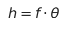
h is the image height of the focus from the optical axis (scan position), f the F-Theta focal length and θ the galvanometer deflection angle (radians); this linear relation makes spot position proportional to galvanometer control voltage and underpins plane calibration in software such as EZCAD
The focus thus lands on a plane and spot spacing is uniform across the whole field. The F-Theta focal length also sets the field size: for a fixed scan-angle range, a longer focal length gives a larger field but also a larger spot.

d_spot is the focused spot diameter, λ the wavelength, f the focal length and D_beam the incident beam diameter; a longer focal length or a thinner beam gives a larger spot and lower energy density
2.2 Telecentricity: making edge beams perpendicular to the work surface
In an ordinary F-Theta lens, the beam focused at the edge of the field is tilted: the chief ray (beam centre) makes an angle with the work-surface normal, called the telecentric angle (chief-ray incidence angle). This angle is about 8°–17° on ordinary lenses and has three consequences: edge spots are projected into ellipses (becoming larger), marking line widths are uneven, and once the workpiece departs from the focal plane the landing position drifts laterally.
A telecentric lens, through a special stop and lens-group design, makes the chief ray at every field point emerge parallel to the optical axis (perpendicular to the work surface), pressing the telecentric angle below 4° (≤1° at the high end). With the beam arriving perpendicularly, even if the workpiece height varies by Δz, the lateral focus position barely moves:
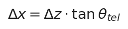
Δx is the lateral landing drift caused by a workpiece height variation Δz; θ_tel is the telecentric angle error, i.e. the maximum deviation of the chief ray from the work-surface normal — note that it is not the galvanometer’s mechanical scan angle, so never substitute the scan angle into this formula; for ideal telecentricity θ_tel tends to zero and height drift tends to zero
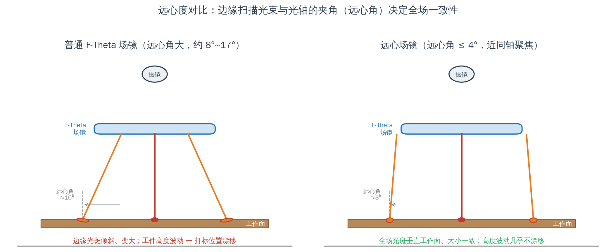
Telecentricity comparison: an ordinary F-Theta lens has tilted edge beams (telecentric angle about 16°) and enlarged elliptical spots; a telecentric lens keeps beams perpendicular to the work surface across the whole field, with uniform size
Source: drawn by the Soar Laser technical team
2.3 Achromatism: bringing multiple wavelengths to one focus
Optical glass has different refractive indices at different wavelengths: shorter wavelengths have a higher index and a shorter focal length. Thus the same lens focuses 1064 nm infrared and 650 nm/532 nm visible light at different positions — axial (longitudinal) chromatic aberration. For a single thin lens, axial focal separation is roughly proportional to focal length and inversely proportional to the glass Abbe number V (reciprocal dispersion), of order Δz ≈ f / V. In a coaxial vision system the camera focuses using visible light while the laser is infrared — under an ordinary lens, ‘where the camera sees clearly’ and ‘where the laser actually focuses’ may differ by several millimetres.
An achromatic design uses a crown-glass (low dispersion, high Abbe number V) positive lens plus a flint-glass (high dispersion, low Abbe number V) negative lens. The optical power of a single thin lens is φ=(n−1)/R; its chromatic aberration is proportional to power and inversely proportional to Abbe number, so a doublet cancels the two elements’ aberrations while meeting the focal-length requirement:

φ is the lens power (1/f) and V the Abbe number (reciprocal dispersion); the first expression makes the positive and negative lens aberrations cancel (achromatic condition), the second keeps total power unchanged — combining a low-dispersion crown positive lens with a high-dispersion flint negative lens gives a common focus at two design wavelengths. A telecentric achromatic field lens integrates this achromatic group with the telecentric stop and F-Theta flattening design in one lens group
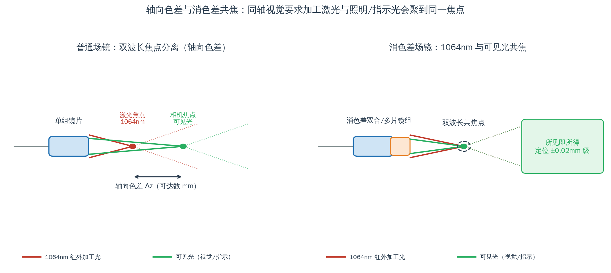
Axial chromatic aberration and achromatic confocal focusing: an ordinary lens separates the two-wavelength foci (axial Δz can reach several millimetres), while an achromatic lens converges the 1064 nm processing beam and visible light to the same focus
Source: drawn by the Soar Laser technical team
3. Structure and Classification
Typical structure: a telecentric achromatic F-Theta lens is a multi-element (usually 3–6) large-aperture lens group housed in a metal barrel, with a standard thread or flange at the entry (commonly M85×1, M79×1, M58, etc.), the elements made of fused silica (UV) or optical glass (visible/IR) with anti-reflection coatings for the corresponding band. Inside the group are arranged the F-Theta flat-field subgroup, the telecentric stop position, and the achromatic positive/negative lens pair.
| Classification dimension | Type | Description |
|---|---|---|
| By wavelength band | Infrared (mainly 1064 nm) | Fibre laser marking/welding, with 650 nm red-vision achromatisation |
| Green (532 nm) | Green precision cutting/marking, with visible-light vision | |
| Ultraviolet (355 nm) | Fused silica construction, UV cold processing, with UV/visible dual wavelength | |
| By number of achromatic bands | Dual-wavelength achromatic | Most common, e.g. confocal at 1064+650 nm or 355+532 nm design wavelengths |
| Multi-wavelength / broadband achromatic | Covers a wider band, with more elements and higher cost | |
| By telecentricity | Standard telecentric (≤4°) | Meets most coaxial vision / precision marking needs |
| High-grade telecentric (angle ≤1°) | Micro-hole drilling, semiconductor microfabrication, situations extremely sensitive to perpendicularity |
4. Key Parameters in Detail
| Parameter | Meaning | Selection point |
|---|---|---|
| Design wavelength / band | The two (or more) wavelengths the achromatisation targets and the AR coating band | First priority; must cover both the processing and vision/alignment wavelengths; not the wider the better |
| F-Theta focal length f | Determines scan field size and spot size | Field-versus-spot trade-off: longer focal length = larger field + larger spot |
| Scan field | Effective marking area, e.g. 65×65 or 100×100 mm | Choose by the largest workpiece dimension, with margin |
| Telecentric angle | Angle between the edge chief ray and the optical axis | Coaxial vision / drilling requires ≤4°, ultra-high precision ≤1° |
| Working distance WD | Distance from barrel end to the focal plane | Determines workpiece height / fixture clearance; choose a long WD for stepped or tall parts |
| Incident beam diameter / spot | Matches the galvanometer output beam diameter and sets the focused spot | Must match the galvanometer aperture and beam expander, otherwise the quoted spot is not achieved |
| Mounting thread | Thread at the barrel entry, e.g. M85×1 | Must match the galvanometer / lens holder; changing brand often needs an adapter |
| Element material / coating | Fused silica (UV) or optical glass, with AR coating | Transmittance >96%; at high power check damage threshold and coating |
5. Characteristics: Advantages and Limits
Advantages:
- Uniform across the field: telecentric design keeps edge spots as round and small as the centre, marking line widths even, drilled holes round and taper-free.
- No drift with height variation: the beam is perpendicular to the work surface, so with stepped, warped or poorly fixtured workpieces the landing position barely changes — critical for drilling and cutting.
- What you see is what you get: achromatism makes the camera focus coincide with the laser focus, giving coaxial vision alignment accuracy on the order of ±0.02 mm.
- Multi-wavelength support: one scan head can serve UV/green/IR processing plus visible alignment and vision capture.
Limits and costs:
- High cost: multi-element achromatic + telecentric design, fused silica and precision assembly make it markedly more expensive than an ordinary field lens.
- Larger size, restricted working distance and field: telecentric designs usually need a longer lens group and more optical space, and at a given focal length the field is often smaller than that of an ordinary lens.
- Band-specific: achromatisation is optimised only for the design wavelengths; outside them chromatic aberration can be worse, so it is not a ‘universal broadband lens’.
- Spot / energy-density trade-off: telecentric designs and long working distances often come with longer focal lengths and larger spots, so ultra-fine marking requires a balanced choice.
- Thermal lensing remains: achromatisation removes chromatic aberration between wavelengths, but the overall focal-plane drift (thermal lens / thermally induced defocus) caused by lens heating from absorbed laser power remains; high-power continuous processing needs water cooling or dynamic Z-axis focus compensation, and achromatisation does not mean the focus stays stable forever.
6. Typical Applications and Selection Guidance
6.1 Coaxial vision alignment marking (the most typical application)
The camera shares one axis with the laser through a beam splitter — wherever the laser marks, the camera sees. The camera focuses using visible light (commonly 650 nm red illumination) while processing uses 1064 nm infrared. The lens must achromatise both wavelengths and guarantee telecentricity, otherwise the crosshair alignment point and the laser landing point are offset. After correction, absolute position accuracy can reach the 0.02 mm level, widely used in precision marking and character traceability for 3C electronics.
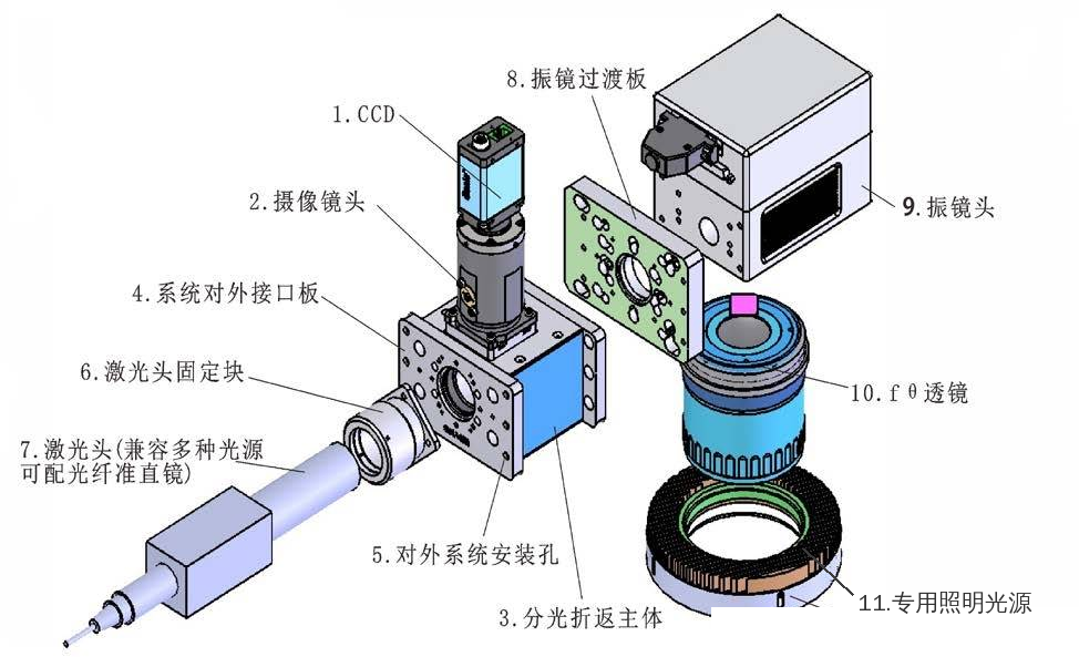
Exploded structure of a coaxial vision laser marking head: the CCD camera ① and imaging lens ② capture from the top, the laser head ⑦ enters from the side and is folded by the beam-splitter body ③, and the galvanometer ⑨ connects below to the fθ lens ⑩ and dedicated illumination source ⑪, laser and visible imaging light sharing one optical path
Source: general industry structural diagram
6.2 Laser drilling and precision cutting
Drilling requires vertical hole walls and consistent diameters. A telecentric lens makes the edge beam incident perpendicularly, avoiding the tapered holes an ordinary lens produces at the edge; when cutting stepped or curved parts, telecentricity keeps height variation from shifting the hole. Such applications commonly require a telecentric angle ≤1°.
6.3 Multi-wavelength / dual-wavelength processing
Systems such as UV + green combined processing or processing light + alignment light on a common path use an achromatic lens to bring the wavelengths to one focus, removing the need to switch between multiple lenses. Typical cases include battery tab cutting for new-energy cells, dual-wavelength fine processing and semiconductor chip micro-welding.
6.4 Selection decision steps
| Step | What to determine | Notes |
|---|---|---|
| ① Band | Processing wavelength + vision/alignment wavelength | E.g. 1064+650 nm or 355 nm + visible; fix the achromatic band first |
| ② Field | Largest workpiece dimension | Choose a nominal field ≥ the workpiece, with >10% margin |
| ③ Telecentricity | By accuracy / perpendicularity requirement | Vision / drilling ≤4°, ultra-high precision ≤1° |
| ④ Working distance | Workpiece height, fixture clearance | Choose a long WD for stepped or tall parts |
| ⑤ Beam / interface | Galvanometer aperture, beam diameter, thread | Match the galvanometer, beam expander and lens holder |
Selection examples:
- 1064 nm fibre marking + 650 nm coaxial vision, field within 100×100 mm: choose an IR telecentric achromatic lens, 1064/650 dual-wavelength achromatic, telecentric angle ≤4°, M85 interface.
- 355 nm UV precision drilling: choose a fused-silica UV telecentric lens (such as the LINOS F-Theta-Ronar UV telecentric series), telecentric angle ≤1°, with a UV galvanometer.
- 532 nm green precision cutting + vision: choose a 532 nm achromatic telecentric lens, checking that the working distance suits the cutting head / fixture clearance.
7. Common Misconceptions
| Misconception | Correct understanding |
|---|---|
| ‘A telecentric achromatic field lens is just a pricier field lens, fine for ordinary marking’ | It is optimised for a specific dual wavelength and telecentricity; for single-wavelength ordinary marking it is poor value, and outside its design band chromatic aberration may even be worse — select by need |
| ‘Achromatic means broadband, so any wavelength can be brought to one focus’ | Achromatisation is precise only at two design wavelengths; away from them chromatic aberration returns — always check that the achromatic band covers your wavelengths |
| ‘If coaxial vision is misaligned it is a camera / calibration problem’ | If the lens is not achromatic, the camera’s visible light and the laser’s infrared have axial and lateral chromatic aberration; axial focus shift can be compensated in software along Z, but the coordinate error at the field edge from lateral chromatic aberration cannot be removed by plane calibration and causes edge alignment failure — first check whether the lens is achromatic |
| ‘A few degrees of telecentric angle error does not matter’ | Telecentric angle directly sets edge spot ellipticity and height drift (Δx=Δz·tanθ); on drilling or stepped parts a few degrees can scrap the work |
| ‘Buy a telecentric lens and the whole machine automatically meets the quoted telecentric angle’ | The quoted telecentric angle assumes the galvanometer exit pupil exactly matches the lens design entrance pupil; galvanometer mounting offset or wrong spacing markedly degrades the machine’s telecentricity, so even with a qualified lens the whole machine must be measured |
| ‘With a telecentric lens, the workpiece can be processed normally off the focal plane’ | Telecentricity suppresses only lateral position drift from height variation; a defocused workpiece still has a larger spot, lower power density and worse processing, so it must stay within the lens depth of focus |
| ‘F-Theta focal length is the working distance’ | f is the scan focal length (used in h=f·θ), while working distance WD is the distance from the lens to the focal plane; they are related but not the same — fixturing must use WD |
| ‘The larger the field, the better’ | At a fixed scan angle, a longer focal length gives a larger field but a bigger spot and lower energy density; telecentric lenses have a more restricted field too — choose by the largest workpiece |
| ‘When changing a lens, only check that the thread fits’ | You must also match the galvanometer aperture, incident beam diameter and band; a mismatched beam will not reach the quoted spot and a wrong band makes the AR coating reflective instead |
| ‘A UV lens can use ordinary optical glass’ | 355 nm UV needs UV-grade material and a UV AR coating; industrial scanning lenses mostly use fused silica (high transmittance, damage resistance, manageable cost), with a few special cases using fluorides such as CaF₂ — ordinary optical glass has low transmittance and is easily damaged, so it cannot be used |
| ‘Vision alignment accuracy depends entirely on camera pixels’ | When the lens is not achromatic/telecentric, optical focus separation and landing drift are systematic errors that camera pixels cannot compensate |
| ‘With a telecentric achromatic lens there is no need to calibrate’ | Even with theoretical confocal optics, galvanometer assembly and lens-group alignment introduce residual error; a telecentric achromatic lens cannot skip system calibration — the whole machine still needs coordinate/distortion calibration to guarantee positioning accuracy |
| ‘A telecentric lens and a telecentric field lens are the same thing’ | Machine-vision telecentric lenses and laser-scanning telecentric field lenses share the principle but differ in structure and use, and cannot be interchanged |
8. History and Development Trends
F-Theta lenses became widespread as laser marking/scanning matured, early ones mostly single-wavelength and non-telecentric, sufficient for conventional marking. As demands grew in two directions, the lens evolved: first, coaxial vision alignment became standard in high-end marking/welding, requiring the lens to bring the processing and visible imaging wavelengths to one focus and driving the achromatic lens; second, laser drilling, precision cutting and semiconductor microfabrication raised requirements on hole perpendicularity and field-wide consistency, driving the telecentric lens. Their combination produced today’s telecentric achromatic F-Theta lens.
In trends, the spread of ultraviolet (355 nm) and ultrashort-pulse (picosecond/femtosecond) cold processing is driving demand for telecentric achromatic lenses in fused silica with high damage threshold and low group-delay dispersion (GDD); multi-wavelength combined processing (UV+green, processing+vision integration) is pushing broader-band achromatic designs; mainstream optical makers (such as Excelitas/LINOS F-Theta-Ronar telecentric series, Jenoptik JENar Silverline, Nanjing Wavelength) keep improving telecentricity, transmittance and miniaturisation. For integrators, the telecentric achromatic lens is changing from an ‘option’ to a ‘standard’ in high-precision vision equipment.
9. References and Further Reading
- RP Photonics Encyclopedia, Scanning Lenses (Scanning Lenses / F-Theta entry), https://www.rp-photonics.com/scanning_lenses.html
- RP Photonics Encyclopedia, Achromatic Optics (achromatic optics / achromatic lens entry), https://www.rp-photonics.com/achromatic_optics.html
- RP Photonics Encyclopedia, Field Lenses (field lens entry), https://www.rp-photonics.com/field_lenses.html
- Edmund Optics, Introduction to Aberration Theory (application note covering chromatic aberration and field curvature), https://www.edmundoptics.com/knowledge-center/application-notes/optics/introduction-to-aberration-theory/
- Wikipedia, Achromatic Lens (principle and history of achromatic lenses), https://en.wikipedia.org/wiki/Achromatic_lens
- Excelitas / LINOS, F-Theta-Ronar Telecentric Lenses (telecentric f-theta lens products and data sheets), https://www.excelitas.com/product/f-theta-ronar-lenses
- Jenoptik, JENar Silverline F-Theta Lenses (F-Theta lens products across wavelength bands)
- W. J. Smith, Modern Optical Engineering, 4th ed., McGraw-Hill, 2007 (chapters on aberration, chromatic aberration and scanning lenses)
Soar Laser · Laser Optics Knowledge Base | Hotline 15927220467 | This article is technical education; refer to product-page parameters for specific specifications
Leave a Reply