


🔧 Fiber Laser Marking Machine
Complete Build Guide from Scratch
For first-time builders: get to know every component → prepare your tools → wire up step by step → configure the software → power-on verification
📑 Table of Contents — Follow the Order
- 1Get to know all components — figure out what each part does first
- 2Prepare tools and materials — have everything ready before you start
- 3220V power distribution architecture — breaker → EMI filter → e-stop → branch switches
- 4Overall wiring overview — see the forest first, then the trees
- 5Step 1: Power distribution area wiring (220V→breaker→filter→e-stop→3 switches)
- 6Step 2: Three power supplies → DC power to each device
- 7Step 3: Marking card J1 → galvo XY signals (6 wires)
- 8Step 4: Marking card J3 → laser control signals (7 wires)
- 9Step 5: Industrial PC → marking card (USB / Ethernet)
- 10Step 6: ⭐ Red light indicator wiring (2 wires, only for external red light)
- 11Step 7: ⭐ Foot switch wiring (2 wires)
- 12Step 8: EZCAD software port configuration
- 13Marking card connector pinout diagrams
- 14Power-on verification checklist
- 15Troubleshooting common faults
1Get to Know All Components
Before wiring anything, understand what each item is and what it does. There are 11 core components + 4 power-distribution protection parts in total:
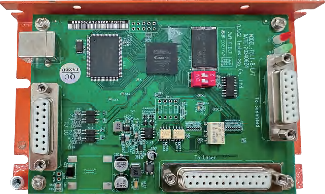
Interfaces: DB15×2 (galvo + laser), DB25×1 (IO/power), USB, Ethernet port
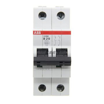
Function: Main power switch + overcurrent/short-circuit protection; trips automatically on leakage or short circuit
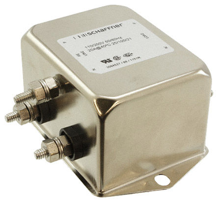
Selection: Rated current ≥ 16A, common-mode + differential-mode filtering, grounded metal housing
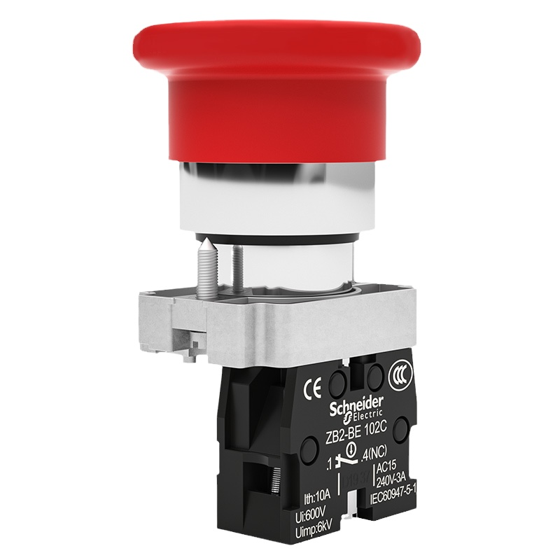
Selection: Normally closed (NC) contact, rated current ≥ 10A, red mushroom head
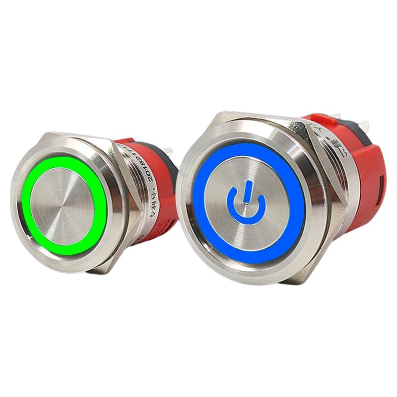
Selection: 22mm metal latching push-button switch with key lock or twist lock, rated current ≥ 10A
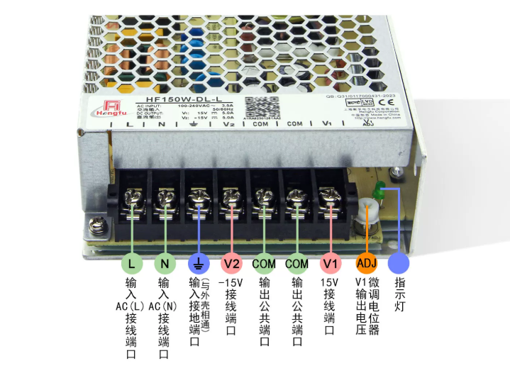
Terminals (left to right): L, N, ⏚, V2(-15V), COM, COM, V1(+15V), ADJ
Note: ADJ is a fine-adjustment terminal, factory calibrated — do not touch it!
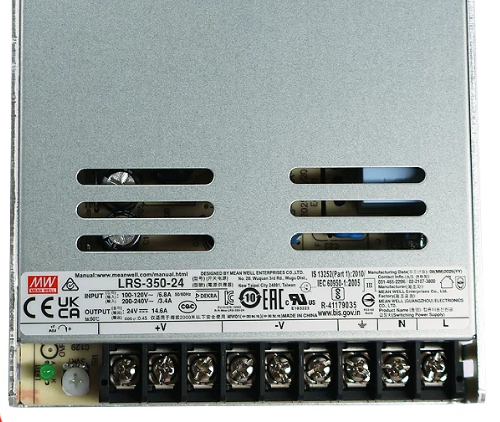
Terminals: L, N, ⏚ (AC input side), -V, +V (DC output side)
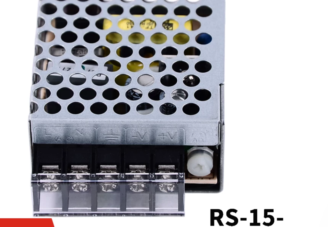
Terminals: L, N, ⏚ (AC input side), -V, +V (DC output side)
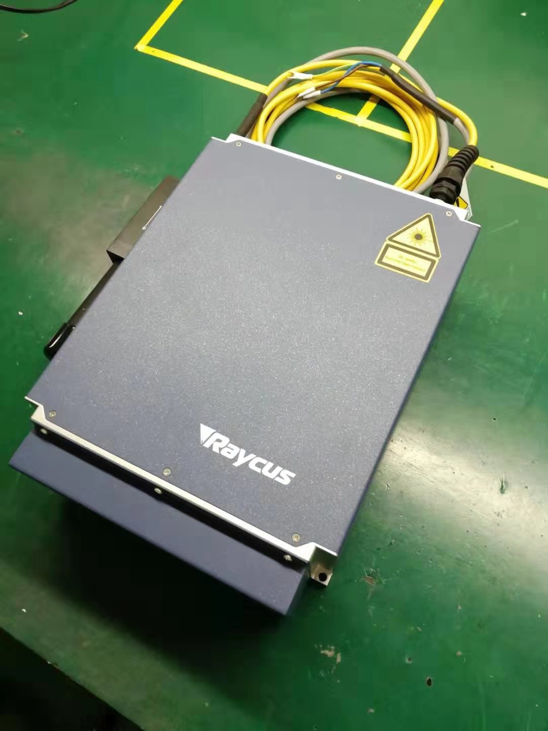
Interfaces: DB25 control port (to marking card J3) + 24V power input (from LRS-350-24)
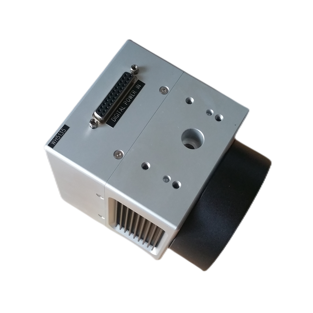
Requires: ±15V power (from the Hengfu supply) + XY analog signals (from the marking card)
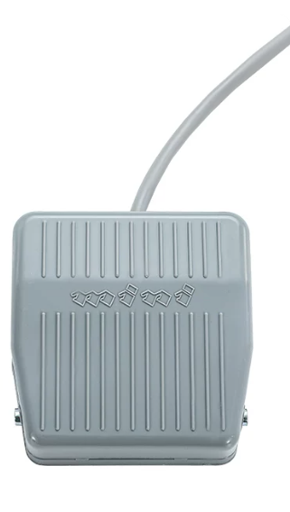
Wiring: Two wires, to marking card J4 Pin 3 (GIN4) and GND
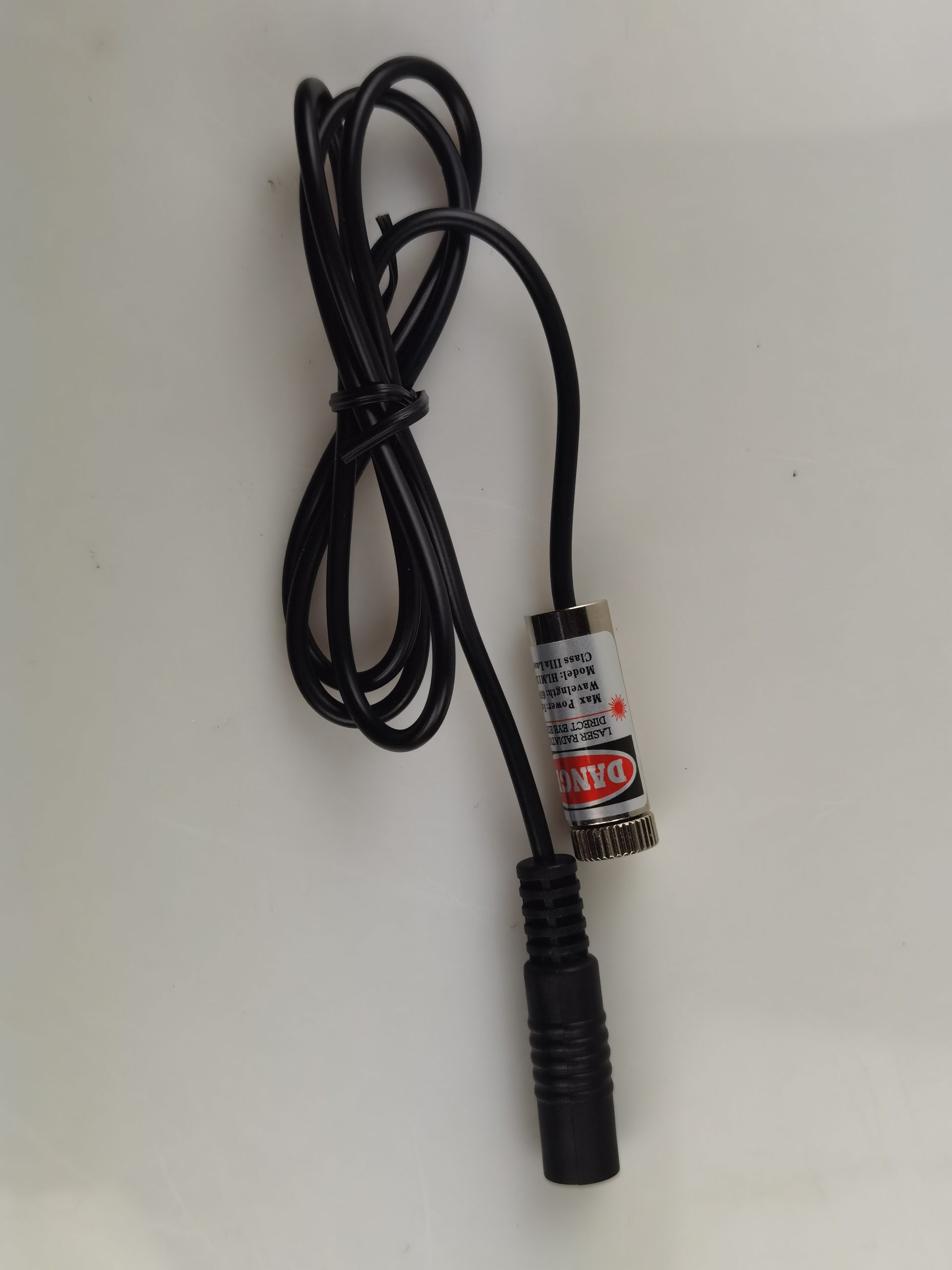
Wiring: Two wires to a marking card J4 OUT port (e.g., Pin 2/OUT4) + GND; the OUT port voltage controls on/off
Note: If the laser has built-in red light, no external red light indicator is needed

Mounting position: Between the laser output aperture and the galvo input aperture, with the red light indicator aimed at the combiner’s reflective face
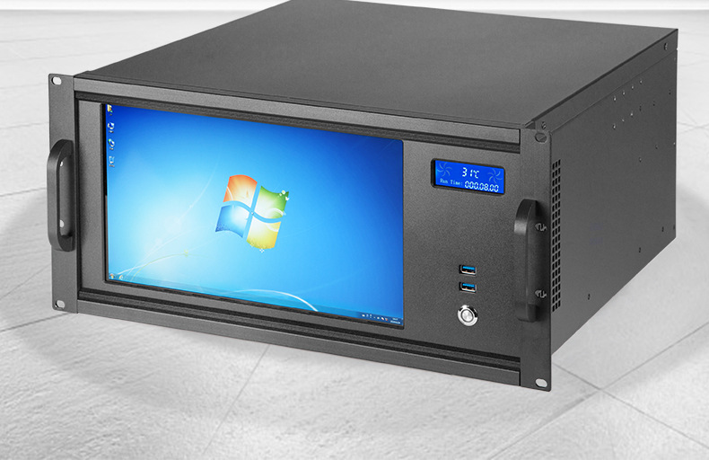
Interfaces: USB-A or Ethernet port
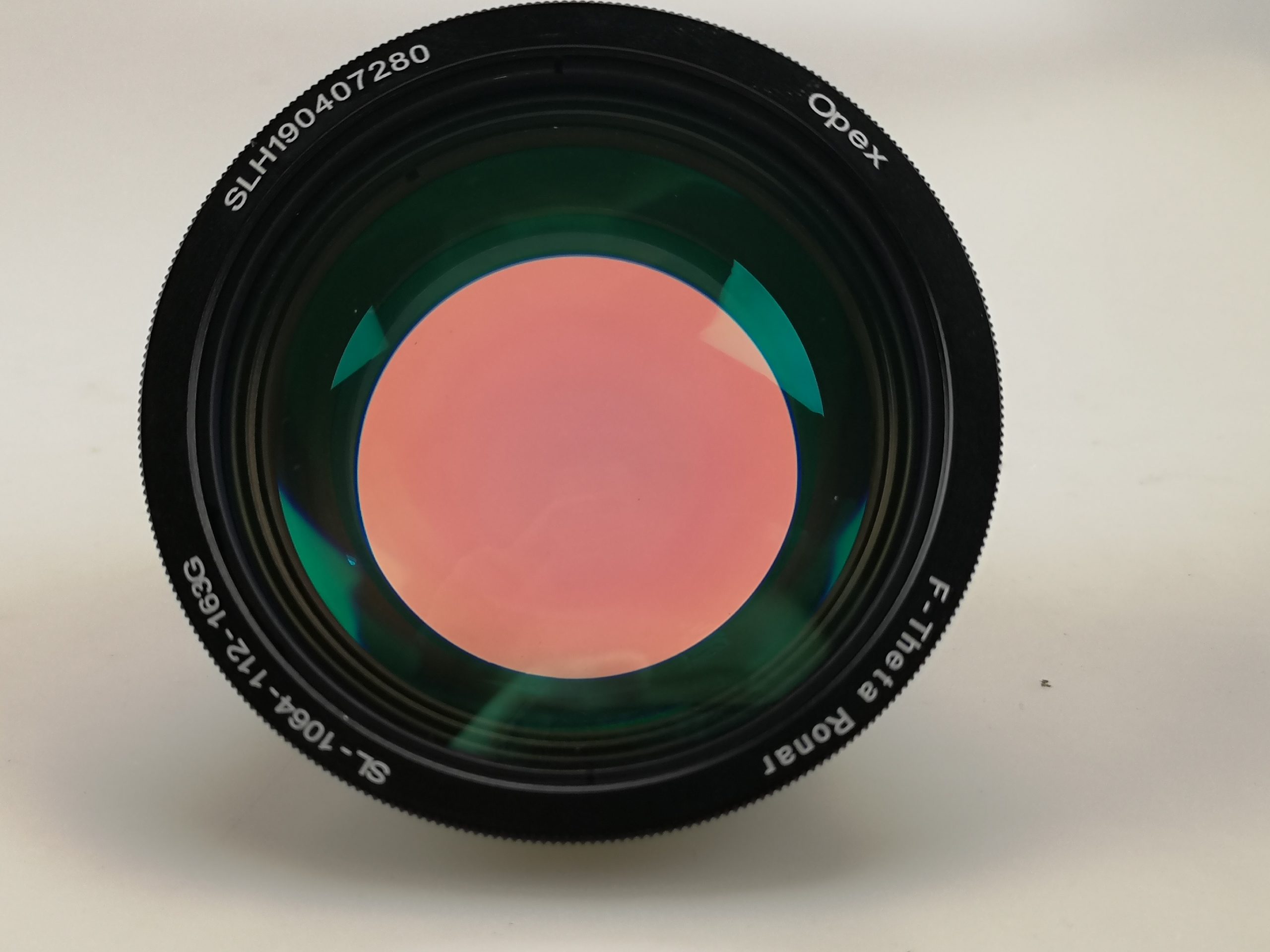
Model decoding (SL-1064-112-163G):
• 1064 = working wavelength 1064nm (fiber laser)
• 112 = nominal marking area 112×112mm (usable area about 110×110mm; incoming beam diameter is about 10mm, not a 112mm entrance pupil)
• 163 = focal length 163mm (determines the marking area size and spot size)
Mounting position: Directly beneath the galvo scanner head, galvo output aperture aligned with the lens input aperture, secured by threading in.
⚠️ Get the working distance rightFirst, distinguish two easily confused concepts: focal length (EFL, effective focal length) is the distance from the lens’ optical principal plane to the focal point — the 163 in the model number is exactly this 163mm focal length; working distance (WD) is the distance from the lowest edge of the field lens housing to the surface of the object being marked. The two are measured from different reference planes, so the values are not equal — focal length ≠ working distance. For this F163/110 field lens, the nominal WD on the datasheet is about 168mm (per the manufacturer’s spec sheet shipped with the lens), not 163mm. Because beam divergence differs slightly from machine to machine, the actual optimal WD will also deviate a little from the nominal value.Fine-tuning method: first set the workpiece height near the nominal WD (about 168mm), then slowly jog the lifting column up and down while listening to the marking sound — when you hear a crisp “crack-crack” and feel the strongest marking force, that is the optimal working distance; stop adjusting. Keep it a fine adjustment — the deviation is not large. A wrong working distance causes a larger spot, blurry edges, insufficient energy density that fails to mark, and unclear marking.
💡 Three views: Front (model engraving visible) / Side (threaded mount) / Top (lens + coating reflections)
PATHInstallation Diagram: Field Lens + Beam Combiner + Red Light Indicator

① Field lens mounts below the galvo, galvo output aperture aligned with the lens input aperture, fixed with screws.
② Beam combiner mounts before the galvo input aperture; the laser fiber head passes through the combiner’s center hole, and the red light indicator is aimed to reflect off the combiner’s side face.
③ The red light and the laser must be precisely aligned at the combiner; otherwise the red-light preview position will deviate from the actual marking position.
④ Installation order: galvo → field lens → beam combiner → red light indicator. Mount the galvo and field lens first, then install the combiner and align the optical path.
2Prepare Tools and Materials
Before wiring, prepare the following tools and materials so you don’t have to hunt for them midway:
• 220V mains power is lethal — always disconnect power before working!
• Keep the main switch OFF while wiring
• If you are not sure you can work safely, get help from a qualified electrician
4Overall Wiring Overview
See the big picture first, then the details. The diagram below shows how all components connect:

① 220V mains → split into three branches feeding the three power supplies
② RS-15-5 outputs 5V → powers the marking card
③ LRS-350-24 outputs 24V → powers the laser source
④ Hengfu HF150W-DL-L outputs ±15V → powers the galvo scanner
⑤ Marking card J1 (DB15) → galvo XY signals
⑥ Marking card J3 (DB25) → laser control signals (PWM+ / LASER+)
⑦ Marking card J4 Pin 2 (OUT4) + GND → external red light indicator (not needed if the laser has built-in red light)
⑧ Marking card J4 Pin 3 + GND → foot switch
⑨ Industrial PC → USB → marking card
PWR220V Power Distribution Architecture (EMI Immunity + Safety Protection)
The machine contains several high-frequency switching power supplies (laser 350W, galvo 150W, marking card 15W) that generate substantial electromagnetic interference (EMI).
Meanwhile, the laser and galvo are precision devices that demand clean power. Poor distribution causes:
① Jittery or unclear marking lines (power noise interfering with galvo signals)
② Unstable marking card communication (USB/network interference)
③ Grid pollution (affecting other equipment on the same circuit)
④ Failure to cut power promptly on short circuit/overload (safety hazard)
Distribution chain (from mains to each power supply):

220V mains → 2P breaker (main protection, trips automatically on overload/short circuit)
→ EMI filter (removes electromagnetic interference for clean power)
→ Emergency stop switch (press to cut the machine’s 220V instantly; twist to reset)
→ splits into three branches → latching switches ①②③ (independently controlling power to the laser / galvo / marking card)
Why an independent switch for each power supply?
① Maintenance safety: power only the marking card and galvo while debugging software, keeping the laser de-energized
② Longer life: de-energize the laser separately when idle to reduce wasted operating hours
③ Troubleshooting: switch off a problem branch alone without affecting the rest
④ Misoperation prevention: latching design keeps non-operators from toggling at will
5Step 1: Power Distribution Area Wiring (220V→breaker→filter→e-stop→3 switches)
Before starting, make sure the main breaker is OFF. After wiring, double-check everything carefully before powering up.
Following the distribution architecture, the 220V mains enters the cabinet, is wired in series in the order below, and finally splits into three branches to the three power supplies:
① 220V mains incoming (L live / N neutral / PE yellow-green earth)
→ connect to the upper input terminals of the 2P breaker (L to left pole, N to right pole, PE passes straight through)
② 2P breaker outgoing (lower L/N)
→ connect to the EMI filter LINE terminals (L to L, N to N, PE to the filter’s housing screw)
③ EMI filter LOAD outgoing (L/N/PE)
→ connect to the emergency stop switch input (normally closed NC contact, in series with the L wire)
④ E-stop outgoing
→ split into three branches, each going to the input of one of the three 22mm latching switches
⑤ Three 22mm latching switch outputs:
• Switch ① → LRS-350-24 (laser power supply) L/N/PE
• Switch ② → HF150W-DL-L (galvo power supply) L/N/⏚
• Switch ③ → RS-15-5 (marking card power supply) L/N/PE
Each power supply takes 3 wires, 9 wires in total.
• Mains L (live, brown wire) → RS-15-5 L terminal
• Mains N (neutral, blue wire) → RS-15-5 N terminal
• Mains PE (earth, yellow-green wire) → RS-15-5 ⏚ ground terminal
Tighten the screws with a screwdriver so no wire end can work loose.
• Mains L → L | Mains N → N | Mains PE → ⏚
• Mains L → L | Mains N → N | Mains PE → ⏚
⚠️ Do not connect anything to the ADJ terminal! It is a voltage fine-tune, factory calibrated.
6Step 2: Three Power Supplies → Powering Each Device
The RS-15-5 outputs 5V DC to power the marking card, wired to the card’s J4 DB25 connector.
• RS-15-5 -V terminal → black wire to J4 DB25 Pins 11, 12, 13 (these three pins are paralleled, all GND)
⚠️ Never reverse the polarity! Reversed wiring will burn out the marking card. After wiring, measure with a multimeter to confirm the +V output is 5V±0.2V.
6.2LRS-350-24 → 24V Power to the Laser
• LRS-350-24 -V terminal → black wire to the laser’s power input 24V-
⚠️ Note: Do not power up yet; energize everything together only after all wiring is complete. Confirm correct polarity.
6.3HF150W-DL-L → ±15V Power to the Galvo
The Hengfu supply outputs ±15V DC to power the galvo scanner head, which has matching terminals or a DB25 connector.
• V1 (+15V) → red wire to the galvo’s +15V input
• COM → black wire to the galvo’s GND (you can run one wire from each COM terminal for extra reliability)
• V2 (-15V) → blue wire to the galvo’s -15V input
⚠️ Never swap V1 and V2! V1 is +15V and V2 is -15V; reversing them will burn the galvo driver board.
7Step 3: Marking Card J1 → Galvo XY Signals
The marking card outputs the XY scanning signals through J1 (DB15 connector), controlling the galvo’s direction of movement.
• Pin 1,9 → CLK± (clock signal)
• Pin 2,10 → SYNC± (sync signal)
• Pin 3,11 → X± (X axis signal) ← to galvo X axis
• Pin 4,12 → Y± (Y axis signal) ← to galvo Y axis
• Pin 5,6,7 → reserved
• Pin 8,15 → GND (signal ground) ← to galvo ground
Use shielded or coaxial cable, with the shield grounded at one end only, to reduce interference.
8Step 4: Marking Card J3 → Laser Control Signals
The marking card controls the laser’s beam on/off, power, frequency and more through J3 (DB25 connector). A 25-wire ribbon cable normally plugs straight in.
• Pin 7 (PWM-) + Pin 20 (PWM+) → pulse power control signal, controlling laser power and frequency
• Pin 18 (LASER-) + Pin 19 (LASER+) → laser enable signal, controlling beam on/off
• Pin 10, 14 (GND) → control signal reference ground
• Pin 17 (VCC) → 5V power output (optional, powers the laser control board)
Other pins:
• Pin 1-6 (P0-P5) → power encoding (no output in digital mode)
• Pin 9 (QKILL) → Q-switch control
• Pin 11-12, 16, 21 → laser status feedback inputs
• Pin 22 (REDPT) → red light indication signal (reserved on some versions)
• Pin 23 (EMSTOP) → emergency stop signal
• Pin 13, 24, 25 → left floating
9Step 5: Industrial PC → Marking Card
Use a USB 2.0 A-to-B cable: one end into the industrial PC’s USB-A port, the other into the marking card’s USB-B port.
Method B (alternative): Ethernet connection
Connect the industrial PC’s network port to the marking card’s Ethernet port with a network cable.
Once connected, install the EZCAD software on the industrial PC. After launching, it should detect the marking card.
10Step 6: ⭐ Red Light Indicator Wiring (External Red Light)
→ No external red light indicator needed
→ No extra wiring needed
→ No red-light preview output port to set in the software
If this is your case, simply skip this step.
Optical path: laser → beam combiner → galvo → field lens
The red light enters the combiner from the side and shares the laser’s path to the work surface.
Wiring needed: the indicator’s two wires go to one OUT port of marking card J4 + GND. When that OUT port outputs voltage, the red light turns on and previews the marking position.
• Wire 1: J4 Pin 2 (OUT1) → the indicator’s positive (+)
• Wire 2: J4 Pin 11, 12, or 13 (GND) → the indicator’s negative (-)
How it works: when “Red Light Preview” is enabled in the software, the marking card outputs voltage through the selected OUT port and the indicator lights up. The red light travels the same optical path as the laser (via the combiner) — if the red dot lands correctly, the laser marks correctly.
💡 You may use any free OUT port (OUT1-OUT8), but the software setting must match the port you actually wired.
① The OUT port is a TTL-level output with current ≤ 10mA. If the red light module draws more (operating current > 10mA), do not connect it directly — add a relay or driver board to amplify the current.
② Some indicators have their own independent power supply and only need an on/off control signal; in that case, connect the OUT port to the control input.
③ The red light module mounts beside the galvo (at the combiner’s input aperture); adjust the optical path so it overlaps the main laser path.
Open EZCAD → press F3 to open the parameters → find “Output Ports” → “Red Light Preview Output Port”:
• If you wired Pin 2 (OUT4) → select OUT4 in the software
• If you wired Pin 10 (OUT5) → select OUT5 in the software
• Rule: the software setting must match the OUT port number you actually wired
11Step 7: ⭐ Foot Switch Wiring (Normally Open)
• Wire 1: one end of the switch’s NO contact → J4 Pin 3 (GIN4)
• Wire 2: the other end of the NO contact → J4 Pin 11, 12, or 13 (GND)
Pressing short-circuits Pin 3 to GND → marking triggers. Releasing opens the circuit → it stops.
GIN4 is the only input on the marking card with hardware filtering. A foot switch is a mechanical contact, and pressing it produces tiny contact bounce (lasting tens of microseconds).
• Wired to GIN4: the filter automatically removes bounce pulses <120μs → one press, one mark ✅
• Wired to GIN14/GIN15 (no filtering): bounce may be read as multiple triggers → one press, two marks ❌
Contact resistance must be < 100Ω.
① Open EZCAD → press F3 → “Ports” → “Start Marking Port” → choose GIN4
② Press F3 → “Others” → check ✅ “Enable marking start signal latch mode”
12Step 8: EZCAD Software Port Configuration
With all wiring complete, open EZCAD on the industrial PC and configure as follows:
Set to ON = CO2/YAG mode
13Marking Card Connector Pinout Diagrams
J4 DB25 — Power + IO Interface
IN14
OUT4★
IN4★
V+
V+
STRT
IN15
OT5
GND
GND
GND
XD+
XP+
Pin 1,9 GIN14/GIN15 general inputs
Pin 2,10 OUT1/OUT5 general outputs (OUT1 → red light indicator)
Pin 4,5 5V power input +
Pin 11-13 GND power ground
J3 DB25 — Laser Control Interface (Fiber Mode)
P0
P1
P2
P3
P4
P5
PWM-
PWMTTL
QKILL
GND
LS0
LS1
GND
VCC
LSR-
LSR+
PWM+
RED★
EMST
DA1
DA2
LS2
LS3
Pin 18,19 LASER± laser enable
Pin 10,14 GND reference ground
Pin 17 VCC 5V output
14Power-On Verification Checklist
After all wiring and software configuration are done, power up in the order below and verify item by item:
① 2P breaker is OFF
② Emergency stop is pressed (open)
③ All three 22mm latching switches are OFF
④ All terminal screws are tight, with no exposed wire ends
① Close the 2P breaker → confirm the EMI filter indicator lights (if fitted)
② Twist to reset the emergency stop → confirm the main circuit is live
③ Turn on switch ③ → energize the RS-15-5 (marking card 5V supply) → confirm the marking card LED lights
④ Turn on switch ② → energize the HF150W-DL-L (galvo supply) → confirm the galvo homes
⑤ Turn on switch ① → energize the LRS-350-24 (laser 24V) → confirm the laser’s indicator is normal
- Close the 2P breaker → is the filter live (confirm via indicator/multimeter)
- Reset the e-stop → do the three 22mm switch inputs have 220V
- Power the marking card 5V → does the on-board LED light up
- Open EZCAD → does it detect the marking card (no errors)
- Power the galvo → does it perform a “homing” movement (mirrors twitch slightly then settle)
- Click the software’s “Red Light” button → does the indicator light up
- Press the foot switch → does the software respond (status bar changes)
- Place scrap material on the table → press the pedal → does it mark properly
- Check that the marking is clear and positioned correctly
- Check that the galvo moves smoothly with no abnormal noise
① First turn off switch ① → shutting down the LRS-350-24 (laser)
② Then turn off switch ② → shutting down the HF150W-DL-L (galvo)
③ Finally turn off switch ③ → shutting down the RS-15-5 (marking card)
④ Press the emergency stop → ⑤ open the 2P breaker
Principle: shut down the beam first, then the motion, then the brain, and cut the main power last.
15Troubleshooting Common Faults
| Symptom | Possible cause | Solution |
|---|---|---|
| Foot pedal has no response | ① GIN4 not set in software ② Latch mode not checked ③ Wiring mistake |
① F3 → Ports → set start marking port to GIN4 ② F3 → Others → check latch mode ③ Verify Pin 3 and GND wiring |
| One press, two marks | Pedal wired to GIN14/GIN15 (no filtering) | Move it to GIN4 (Pin 3), which has hardware debounce |
| Red light does not light up (external red light) | ① Red light preview output port not selected or wrong ② OUT4 wire loose ③ Red light module draws > 10mA ④ Laser has built-in red light, external unit unnecessary |
① F3 → Output ports → set red light preview output port to OUT4 (match actual wiring) ② Check J4 Pin 2 and GND wiring ③ Add a driver circuit (relay/transistor) ④ Confirm whether external red light is needed |
| Laser does not fire | ① DIP switch SW2 in wrong position ② PWM/LASER wiring wrong ③ Laser 24V not connected |
① Confirm SW2 is set to 1,2 (fiber mode) ② Check J3 Pin 7,20,18,19 wiring ③ Measure LRS-350-24 output with a multimeter for 24V |
| Blurry marking / soft edges / enlarged spot | ① Wrong field lens focal length (area mismatch) ② Working distance (WD) not set correctly (WD ≠ focal length) ③ Lens contaminated or damaged |
① Confirm the focal length matches the marking area (163mm ≈ 110×110mm, 254mm ≈ 175×175mm) ② Check the nominal WD in the lens datasheet (about 168mm for this lens, not the 163mm focal length); set the workpiece near the nominal WD first, then fine-tune by slowly raising/lowering the column — when the “crack-crack” marking sound is strongest, you are at the optimal focus ③ Gently clean the lens with anhydrous ethanol + lens tissue |
| Marking position offset | ① Wrong galvo calibration file ② Red light not calibrated |
① Re-run galvo calibration ② Adjust the red light module until it overlaps the laser path |
| Galvo jitter / abnormal noise | ① ±15V reversed ② Signal line interference |
① Cut power immediately! Check V1(+15V)/V2(-15V) polarity ② Use shielded cable, shield grounded at one end |
| EZCAD cannot detect the card | ① USB cable issue ② Driver not installed ③ No 5V supply |
① Try another USB cable ② Install the Sino-Galvo driver ③ Measure RS-15-5 output for 5V |
| 2P breaker trips immediately on closing | ① Line short circuit (L/N touching) ② Excessive leakage current (PE not properly connected) ③ Breaker rating too low |
① Disconnect all downstream loads and locate the short point one by one ② Verify reliable PE grounding on all equipment ③ Confirm breaker rating ≥ 16A |
| Jittery / unclear marking lines | ① EMI filter not installed ② Signal lines bundled with power lines ③ Poor grounding |
① Confirm the EMI filter is wired in and grounded ② Route signal lines away from 220V lines with ≥ 10cm spacing ③ Check that the ground bar connections are tight |
| Cannot recover after pressing e-stop | ① E-stop not reset properly (must twist to reset) ② E-stop contact wired wrong (should be NC) |
① Twist the e-stop button clockwise to release and reset ② Check that the e-stop is wired to the NC (normally closed) contact |
| One power branch cannot be energized | ① Corresponding keyed latching switch not turned on ② Switch wiring loose ③ Switch rating too low |
① Confirm the 22mm latching switch is ON ② Check the switch’s input/output terminal screws ③ Confirm switch rating ≥ 10A |
Questions? Contact: 15927220467
Leave a Reply