


Optical coatings typically serve two purposes: changing optical properties such as transmittance or reflectance, and protecting vulnerable optical surfaces. For example, a glass substrate can be coated with an aluminum film to become a broadband mirror; a layer of magnesium fluoride can then be added to improve durability, and an additional layer of titanium dioxide can enhance reflectance. Below are Thorlabs optics coated with high-reflectivity (HR) or anti-reflection (AR) thin films.
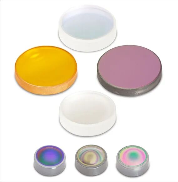
HR-coated optics
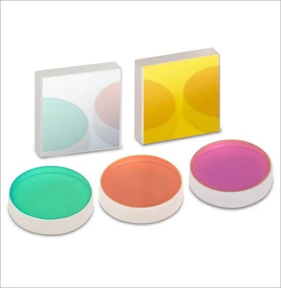
AR-coated optics
Reflection Analysis of Optical Thin Films
The basic working principle of optical thin films can be understood through a single-layer coating. As shown in the figure below, a single-layer film with thickness 𝑡 and refractive index 𝑛₁ is deposited on a substrate with refractive index 𝑛₀.
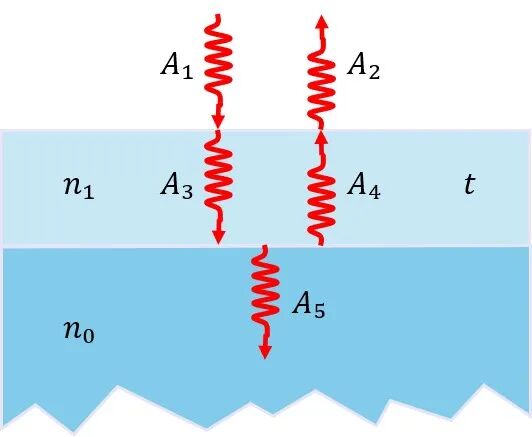
Consider the electric field amplitudes of the five distinct beams in the figure:
- 𝐴₁ is the amplitude of the incident beam (in air/vacuum)
- 𝐴₂ is the amplitude of the reflected beam (in air/vacuum)
- 𝐴₃ is the transmitted beam inside the film (forward propagation)
- 𝐴₄ is the reflected beam inside the film (backward propagation)
- 𝐴₅ is the transmitted beam entering the substrate
Since all amplitudes need to be known relative to 𝐴₁, there are four unknowns. From the continuity of the electromagnetic fields at the two interfaces, these unknowns satisfy the following relations:
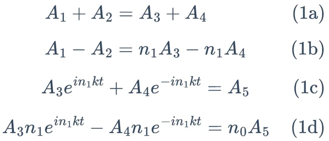
Solving the system of equations gives the general expression for 𝐴₂/𝐴₁:

If the following condition is met:

That is, when the film thickness equals an integer multiple of the wavelength plus one quarter wavelength, 𝐴₂/𝐴₁ can be simplified to:
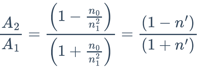
where 𝑛’ = 𝑛₀/𝑛₁² is the effective refractive index of the film-and-substrate combination. The rightmost term of the equation above is therefore the effective Fresnel reflection after coating, showing that a quarter-wave film can change the reflective properties of a substrate.
Single-Layer Anti-Reflection (SLAR) Coating
When the effective refractive index 𝑛’ equals 1, the effective Fresnel reflection of the quarter-wave film and substrate becomes zero:

This is how a single-layer anti-reflection (SLAR) coating works: a low-index film one quarter of a wavelength thick suppresses the Fresnel reflection of a glass substrate. Common glasses have refractive indices between 1.5 and 1.6, so the ideal index for an anti-reflection coating would be about 1.25—but no such material exists. The low-index material commonly used in SLAR coatings is magnesium fluoride.
SLAR calculation example: Suppose an N-BK7 lens needs a single-layer anti-reflection coating. At a design wavelength of 540 nm, the refractive index of N-BK7 is 1.519 and that of magnesium fluoride is 1.379. Calculate the thickness of the magnesium fluoride layer, and compare the reflectance of the lens before and after coating.
At 540 nm, the optical path through the magnesium fluoride layer equals one quarter of the wavelength:
𝑛𝑡 = 𝜆/4 => 𝑡 = 𝜆/(4𝑛) = 97.9 nm
The anti-reflection coating is therefore 97.9 nm thick.
The effective refractive index of the lens plus the anti-reflection coating is:
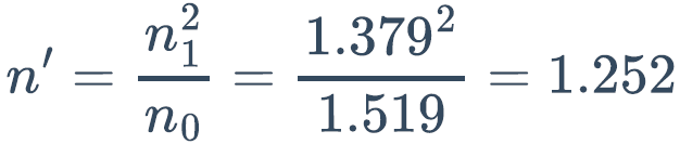
The reflectance of the coated lens is calculated from the Fresnel equations:

The coated lens therefore has a reflectance of 1.25%, while the uncoated lens, calculated from the N-BK7 refractive index of 1.519, has a reflectance of 4.25%. The figure below shows an example of the reflectance of glass with a single-layer anti-reflection coating across the entire visible band.
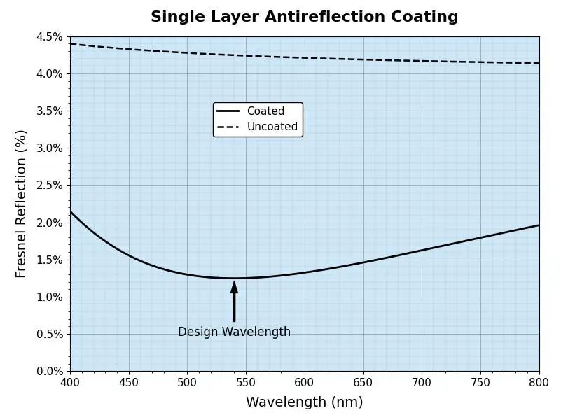
Although a single-layer anti-reflection coating significantly reduces reflectance, many applications demand an even lower and flatter reflectance curve—for example, a few tenths of a percent over a wide spectral range. This calls for multilayer coatings made of different materials.
Thorlabs offers a variety of multilayer broadband anti-reflection (BBAR) coatings and narrowband V-coatings for many transmissive optics such as lenses and windows. The lower left figure below shows all of our BBAR coating types and their wavelength ranges, while the lower right figure shows the reflectance curve of the -A coating for the visible range. That said, some Thorlabs products do use single-layer AR coatings, including the TTL200-S8 tube lens, crystal prism polarizers, and nonlinear frequency-doubling crystals.
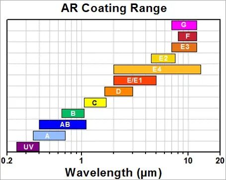
Thorlabs BBAR coating types
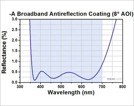
Reflectance curve of the -A coating
Multilayer Coating Structure
To understand the basic working principle of multilayer coatings, assume that a substrate with refractive index 𝑛₀ is coated with 𝑁 pairs of quarter-wave layers whose refractive indices are 𝑛₁ and 𝑛₂. Although only 3 pairs are drawn in the figure below, a real multilayer coating may contain dozens of such pairs.
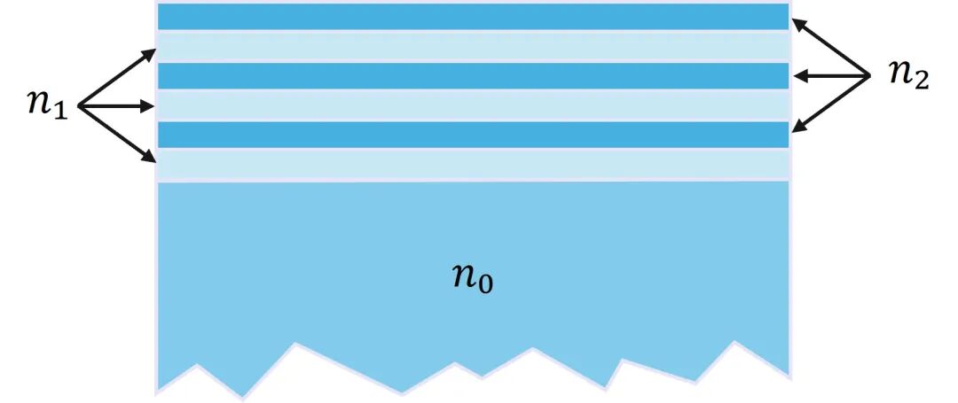
Based on the properties of quarter-wave layers, the effective refractive index of the substrate plus the first layer is:
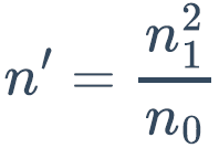
This 𝑛’ serves as the substrate index for the second layer, which gives the effective refractive index of the substrate plus the first pair:
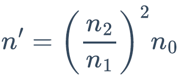
Adding the remaining 𝑁-1 pairs one after another yields the effective refractive index of the entire multilayer system:
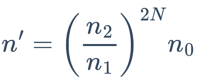
Calculation example: Assume 10 pairs of quarter-wave layers made of low-index (1.38) magnesium fluoride and high-index (2.0) zinc oxide, on an N-BK7 substrate with a refractive index of 1.519.
The effective refractive index of the coated component is:
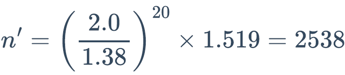
This effective refractive index seems unusually high, and its significance shows in the Fresnel reflectance of the coated component:

The component is therefore in fact a dielectric mirror offering 99.84% reflectance! Of course, this high reflectance applies only at the design wavelength; other wavelengths do not satisfy the quarter-wave layer condition. To analyze the reflectance at other wavelengths, a more general expression for the effective refractive index can be derived from equation (2):

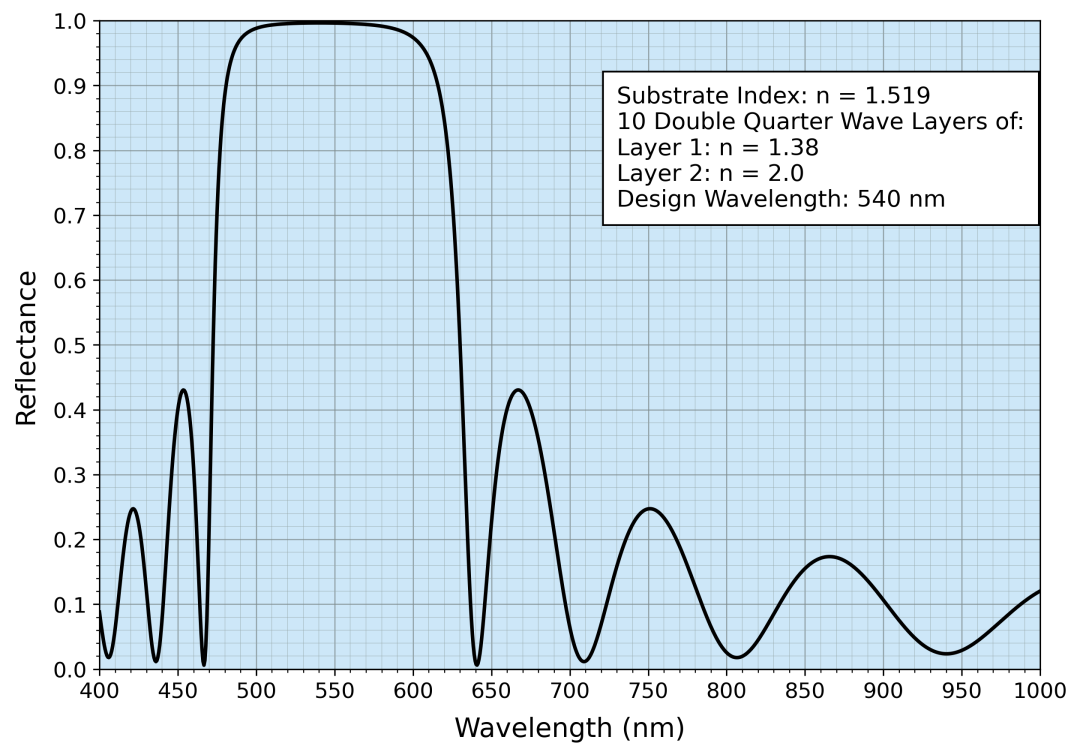
In this way, the index calculated at each step serves as the substrate index for the next layer, giving the effective refractive index and Fresnel reflectance of the whole multilayer at all wavelengths. The figure below shows the reflectance curve of 10 layer pairs. It provides high reflectance only over a relatively narrow spectral range, which is typical of this simple multilayer design: additional layers raise the reflectance but also narrow the bandwidth. In addition, the ripple period in the curve is related to the number of layers—the more layers, the closer the ripples.
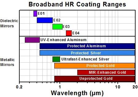
Thorlabs offers a variety of high-reflectivity broadband dielectric coatings optimized for different performance parameters, each with an average reflectance greater than 99%. We also offer several narrowband laser-line dielectric coatings, dielectric supermirrors with 𝑅 > 99.99%, and the broadband metal coatings introduced later. The figure below shows the types and wavelength ranges of Thorlabs high-reflectivity broadband dielectric and metal coatings.
Metal Coatings: Neutral Density Filters
Metal coatings can serve not only as broadband mirrors but also as neutral density (ND) filters, which provide essentially constant attenuation (optical density, OD) over a very wide wavelength range. Metal coatings must be analyzed with complex refractive indices, but the basic process is the same; the amplitudes of both transmitted and reflected light must be considered, and absorption cannot be neglected.
The transmitted amplitude 𝐴₅ can be calculated from equation (1) as:

The transmittance is the product of the squared amplitude ratio and the refractive index:

The reflection amplitude of equation (2) can also be written in complex form:

These formulas require the complex refractive index 𝑛₁ = 𝑛 + 𝑖𝜅.
Chromium-on-glass example: The complex refractive index of chromium at 540 nm is 2.74 + 4.2𝑖. This makes it possible to calculate how the film thickness 𝑡 affects the reflectance and transmittance of chromium-coated glass; the results are shown in the lower left figure below.
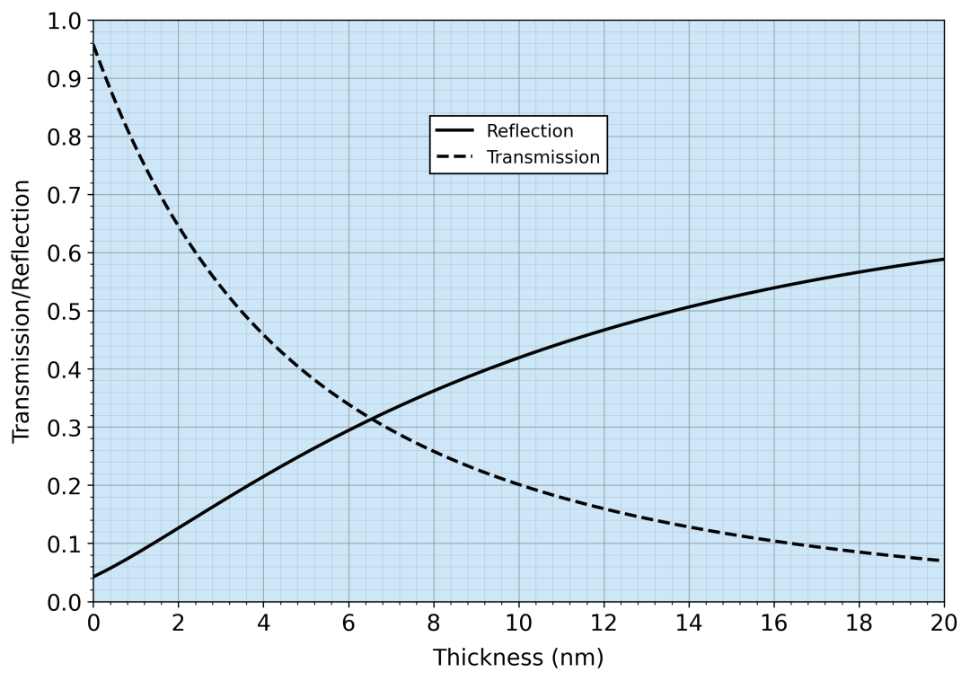
Effect of 𝑡 on 𝑅 and 𝑇
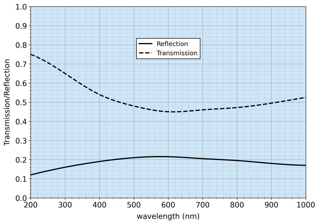
𝑅 and 𝑇 curves of a 4 nm chromium film
As can be seen from the upper left figure, the film must be extremely thin—only a few nanometers—to obtain useful transmitted light. For example, a film only 4 nm thick produces nearly 50% attenuation. The upper right figure shows the reflectance and transmittance of a 4 nm thick chromium film as a function of wavelength.
An ideal neutral density filter should provide a wavelength-independent optical density (OD). In practice, metallic ND coatings usually contain a specific blend of chromium, nickel, and other metals to achieve an extremely flat response curve. Below are the transmittance curves of Thorlabs reflective neutral density filters at different OD values, together with filters whose OD ranges from 0.04 to 4.0.
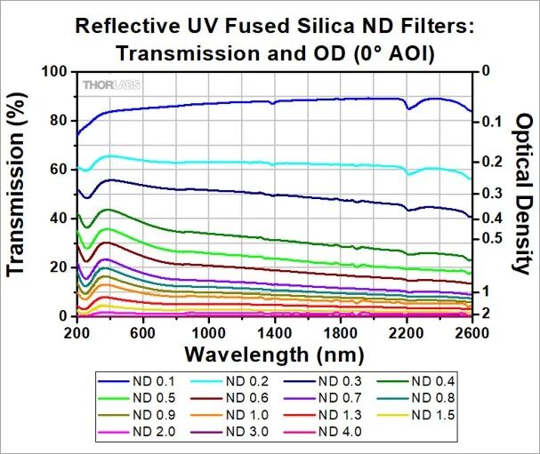
Filters with different OD values
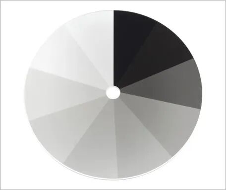
OD: 0.04 – 4.0
Thin Metal Films: Broadband Mirrors
Based on the preceding analysis, a high-reflectivity metal coating must be sufficiently thick, typically between 250 and 500 nm. Because practical metal coatings such as aluminum, silver, and gold are relatively soft, they are usually overcoated with durable dielectric layers that provide protection or enhancement. Protective overcoats use materials such as silicon dioxide or magnesium fluoride; their main purpose is to protect the metal film, though often at some cost to optical performance. Enhanced coatings optimize the reflective performance of metal films—for example, UV-enhanced aluminum and mid-infrared-enhanced gold, or ultrafast-enhanced silver with reduced group delay dispersion.
A protective overcoat is usually a single layer and can be regarded as a specific quarter-wave layer. To understand how an overcoat affects reflectance, we calculate the reflectance using the complex refractive index of the metal coating (at normal incidence):
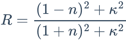
For most metal coatings 𝑛 ≪ 𝜅, so the expression above can be simplified:
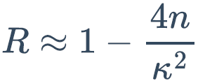
If a quarter-wave layer with refractive index 𝑛₁ is added on top, the effective complex refractive index can be written as:
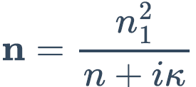
The reflectance then becomes:

Since 𝑛₁ > 1, a protective layer reduces the reflectance. To improve on this, another quarter-wave layer with refractive index 𝑛₂ can be added. Following the same analysis as before, the reflectance of this two-layer system is approximately:
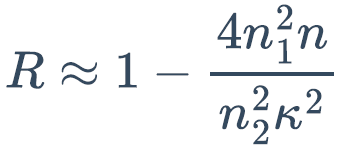
If 𝑛₂ > 𝑛₁, the reflectance increases significantly. For example, depositing quarter-wave layers of magnesium fluoride (𝑛 = 1.38) followed by titanium dioxide (𝑛 = 2.2) on an aluminum film forms an enhancement coating that raises the reflectance.
Leave a Reply