


What Is a Beam-Splitter Coating? How to Split One Beam into Two in a Given Ratio
A beam-splitter coating is an important concept in laser technology, widely used in industrial manufacturing, scientific research and healthcare. This article systematically introduces the core concepts, working principles, key parameters, main types and typical applications of beam-splitter coatings, helping readers build a complete knowledge framework.
Table of Contents
- 1. What Is a Beam-Splitter Coating? Understanding the Core Concepts
- 2. Working Principle: How Is a Beam-Splitter Coating Applied?
- 3. Key Parameters: Understanding the Performance Indicators of Beam-Splitter Coatings
- 4. Main Types: What Kinds of Beam-Splitter Coating Exist?
- 5. Applications: Where Are Beam-Splitter Coatings Used?
- 6. Common Misconceptions: Pitfalls to Avoid
1. Core Concepts: What Is a Beam-Splitter Coating?
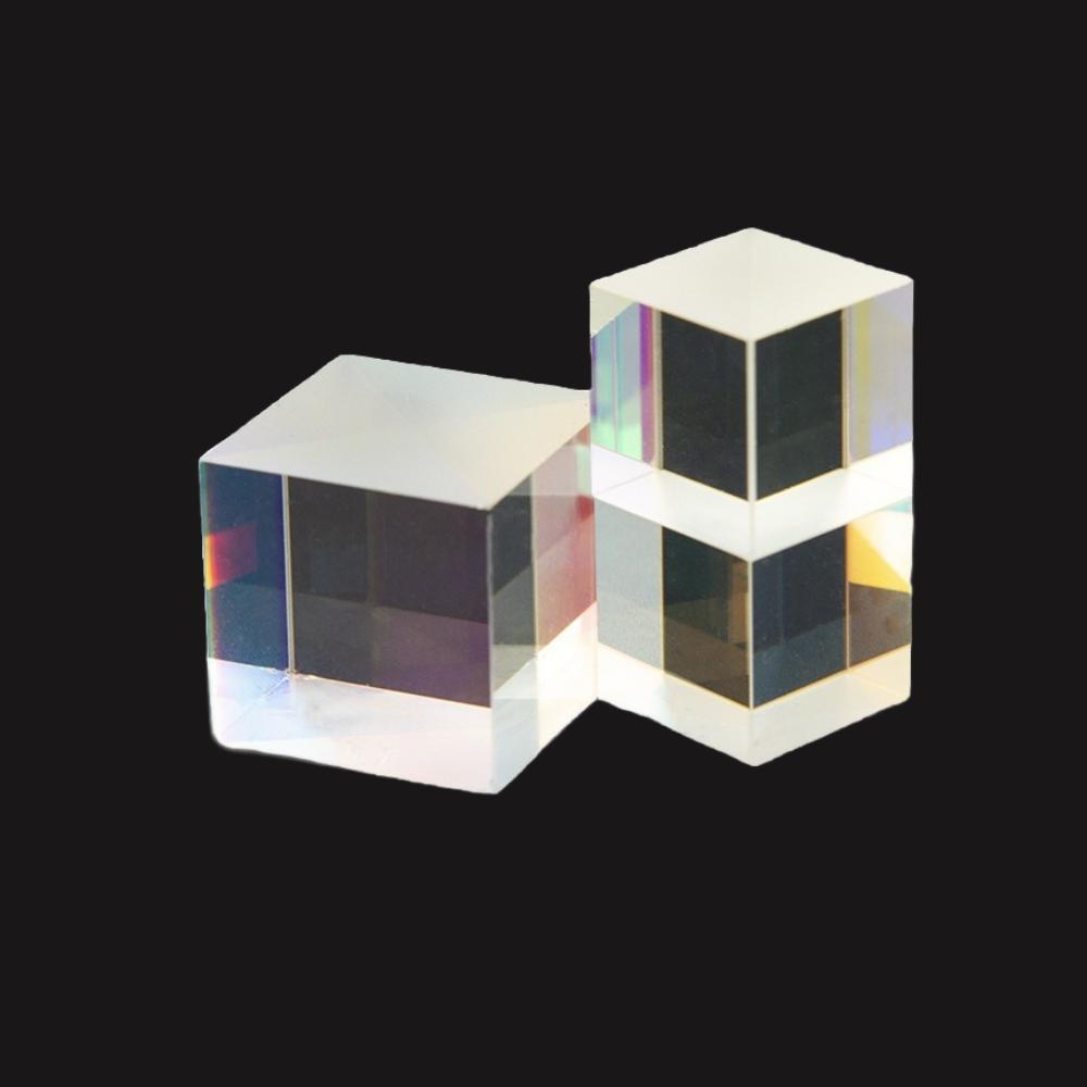
A beam-splitter coating, as its name suggests, is an optical coating that can split one beam into two (or more). When incident light strikes the coating, part is reflected and part continues through, so one beam becomes two travelling in different directions. The most common application of a beam-splitter coating is beam splitting—for example, in a laser interferometer, splitting the laser into a measurement beam and a reference beam, or in an optical instrument, splitting off a small portion of light for power monitoring. A beam-splitter coating is usually deposited on a transparent substrate (such as a glass plate or a prism hypotenuse), forming what we commonly call a beam splitter. The splitting ratio (the ratio of reflected to transmitted light) can be 50:50 or other ratios, designed entirely to customer requirements.
2. Working Principle: How Is a Beam-Splitter Coating Applied?
The working principle of a beam-splitter coating is based on the control of partial reflection plus partial transmission. For a dielectric beam-splitter coating, it uses the interference effect of a multilayer dielectric film; through precise control of layer thickness and materials, the reflectivity and transmittance at the design wavelength reach the specified ratio (e.g. 50% reflection plus 50% transmission). Like a high-reflection coating, it is also formed by alternating high- and low-index materials, but the layer count and thickness are specially optimised so that the energy distribution between reflected and transmitted light exactly meets the requirement. For a metallic beam-splitter coating, it directly uses the characteristics of a thin metal film—partial absorption plus partial reflection plus partial transmission; when the metal film is thin enough, part of the light is reflected, part is absorbed, and part passes through. However, a metallic beam-splitter coating has absorption loss, which is the essential difference between it and a dielectric beam-splitter coating.
💡 An analogy
A beam-splitter coating is like a fork in the road for light—one beam strikes it, part is reflected and part passes through, just as one road splits into two. The splitting ratio can be designed as needed: some split it in half (50:50), while others reflect most and transmit a little, like distributing water flow in a given proportion.
In summary, beam-splitter coatings involve the intersection of multiple disciplines including optics, materials science and precision manufacturing. Mastering their basic principles and key parameters is the foundation for properly selecting and using related products.
3. Key Parameters: Understanding the Performance Indicators of Beam-Splitter Coatings
Understanding beam-splitter coatings requires mastering the following key parameters, which directly determine product performance and application scenarios:
| Parameter Name | Meaning | Why It Matters |
|---|---|---|
| Splitting Ratio | — The most common is 50:50 (half reflected, half transmitted), but special ratios such as 90:10 and 70:30 also exist | Directly affects laser performance and the choice of application scenarios |
| Operating Wavelength | — Single wavelength or broadband, and how large the wavelength range is | A beam-splitter coating’s splitting ratio changes with wavelength; broadband splitting is more difficult |
| Angle of Incidence | — Usually used at 45°, though normal incidence (0°) also occurs | Beam-splitter coatings are usually used at a 45° angle of incidence; deviating from the design angle changes the splitting ratio |
| Polarisation Characteristics | — Whether it is polarisation splitting (PBS) or non-polarisation splitting (NPBS); non-polarising splitters must keep the s- and p-polarisation splitting ratios close | Directly affects laser performance and the choice of application scenarios |
| Substrate Form | — A plate beamsplitter or a cube beamsplitter | Directly affects laser performance and the choice of application scenarios |
| Laser Damage Threshold | — Needs special attention in high-power applications; cemented cubes usually have a lower damage threshold | In high-power applications, the damage threshold of a beam-splitter coating is an important indicator |
The above parameters are interrelated and mutually constrained. In actual selection, a comprehensive trade-off among performance, cost, reliability and other aspects is needed according to specific application requirements.
For more product parameters or selection advice, please contact the Soar Laser technical team.
4. Main Types: What Kinds of Beam-Splitter Coating Exist?
Beam-splitter coatings come in many types, commonly classified as follows: by polarisation characteristics, polarising beam-splitter coatings (PBS)—separate s- and p-polarised light, reflecting s and transmitting p, with a very high extinction ratio; and non-polarising beam-splitter coatings (NPBS)—the splitting ratio is independent of the polarisation state of the incident light, which is more difficult to achieve. By substrate form: plate beam-splitter coatings—deposited on a transparent plate, simple in structure and with a higher damage threshold, but the transmitted light has a lateral displacement; and cube beam-splitter coatings—deposited on the cemented face of two prisms, compact with no displacement, but the damage threshold is limited by the cement layer. By material: dielectric beam-splitter coatings—low absorption and high damage threshold, but polarisation-sensitive; and metal/dielectric hybrid beam-splitter coatings—polarisation-insensitive with broad bandwidth, but with absorption loss. There are also dichroic beam-splitter coatings, which split by wavelength (reflecting one wavelength and transmitting another).
5. Applications: Where Are Beam-Splitter Coatings Used?
Beam-splitter coatings have a very wide range of applications, covering industrial manufacturing, scientific research, healthcare, communications and information, and many other fields. The following introduces several main aspects:
- Beam-splitter coatings are among the most commonly used functional coatings in optical systems. In laser interferometry, the beamsplitter is a core component used to divide the laser into a measurement arm and a reference arm. In laser systems, beam splitters split a small beam from the main laser for power monitoring or sampling analysis. In optical imaging, beam splitters divide optical paths, such as the fluorescence illumination path in a microscope or binocular observation systems. In optical communications, beam splitters (couplers) are used for signal distribution and combining. In laser processing, beam splitters divide the beam to enable simultaneous multi-station processing. A practical tip for salespeople: when a customer asks about a ‘beamsplitter,’ first ask whether they want splitting by power or by polarisation, and whether it is a plate or a cube, because these two categories differ greatly in price and performance.
Typical Application Scenarios in Detail
Scenario 1: Laser Interferometers
Michelson interferometers, Mach–Zehnder interferometers and others all use beam splitters to divide light into two beams, making them core components for precision measurement.
Scenario 2: Optical Communication Systems
beam splitters are used for signal branching and coupling in optical fibre communications, the basic elements for distributing optical power in an optical network.
Scenario 3: Laser Power Monitoring
using a beam splitter to take a small fraction of light for power monitoring enables real-time monitoring of laser output without affecting the main optical path.
Scenario 4: Imaging and Display
beamsplitter prisms and half-silvered mirrors are used in projection displays and AR/VR optical systems to fold optical paths and combine images.
6. Common Misconceptions
Many people have somewhat plausible but mistaken notions about beam-splitter coatings. See whether you fall into any of the following misconceptions:
Misconception 1: A beam-splitter coating is always 50:50.
In fact, the splitting ratio can be designed to order; 50:50 is only the most common, and there are various other ratios; it can even split by wavelength (dichroic) or by polarisation (PBS).
Misconception 2: Dielectric beam-splitter coatings have no loss.
Although dielectric materials have very low absorption, scattering, polarisation imbalance, residual reflection and other factors all cause loss, and at oblique incidence the s- and p-polarisation splitting ratios differ greatly.
Misconception 3: Cube and plate beamsplitters are interchangeable.
Because of the cement layer, a cube beamsplitter typically has a laser damage threshold of only about 1 J/cm² (nanosecond pulses), far lower than a plate beamsplitter; high-power applications must use the plate type.
Misconception 4: The splitting ratio is the same at any angle.
A beam-splitter coating’s splitting ratio is very sensitive to the angle of incidence; using it at an angle that deviates from the design value significantly changes the splitting ratio.
The above are several common misconceptions about beam-splitter coatings. In practical applications, comprehensive judgment is needed based on specific product parameters and use conditions. If in doubt, it is recommended to consult a professional technician.
Leave a Reply