


What Is Beam Profile Measurement? How to See the Cross-Section of a Laser
Beam profile measurement turns the spatial cross-section of a laser beam into an intensity map, and it is the basic way to judge the shape and width of a beam.
Table of contents
- 1. What is beam profile measurement? Getting the core concept straight
- 2. Working principle: how beam profile measurement works
- 3. Key parameters: reading the specifications of a beam profiler
- 4. Main types: what kinds of beam profiler are there
- 5. Applications: where is beam profiling used
- 6. Common misconceptions: pitfalls to avoid
1. Core concept: what is beam profile measurement?
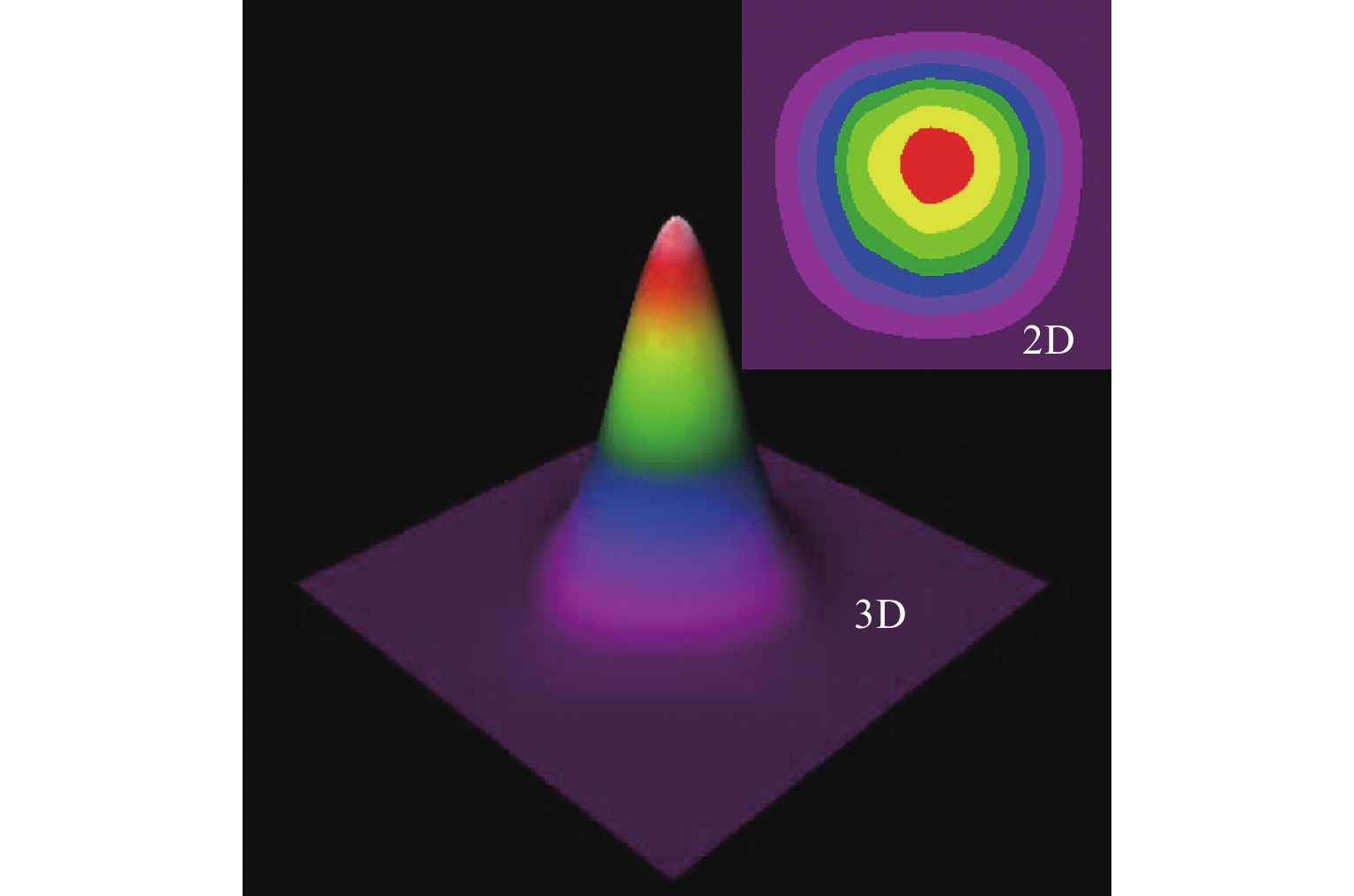
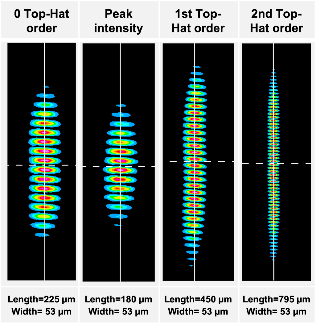
Beam profile measurement turns the spatial cross-section of a laser beam into an intensity map. Beam profiling is the technique of measuring the intensity distribution across the spatial cross-section of a laser beam with a dedicated instrument — the beam profiler (beam profiler, also called a beam analyser). It tells you not only how large the beam is (the beam width) but also what its shape is like: a perfect Gaussian, a hollow centre, or split into several spots?
If the optical power meter tells you “how much energy this beam carries”, a beam quality analyser tells you “how well this beam focuses”, then the beam profiler is like taking a high-resolution CT scan of the laser: it shows the complete intensity map of the beam cross-section. In laser R&D, production QC and optical path alignment, the beam profiler is an indispensable diagnostic tool.
It is reasonable to ask why beam profile measurement deserves an article of its own, and why an accurate measurement matters. Beam profiling is one of the direct determinants of how well a laser application performs: if the spot profile is wrong the cut quality suffers, if the power is measured inaccurately the process is unstable, and if the signal is detected insufficiently the communication distance falls short. Understanding the principle, the parameters and the selection method of beam profiling is the first step toward using a laser well.
2. Working principle: how does beam profile measurement work?
The working principle of beam profiling can be broken down into a few key steps or mechanisms. Laser physics has the reputation of being obscure, but following this line of reasoning it is not difficult at all. Let us go through it step by step:
Beam profilers fall into two main technical families with completely different principles:
### Camera-based beam profilers (camera-based beam profiler)
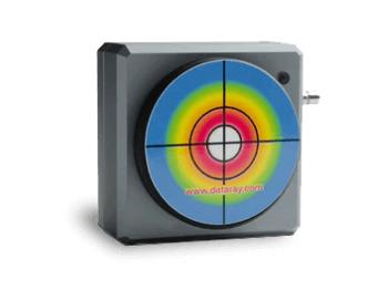
This is the most intuitive and most widely used approach, and it works much like taking a photograph:
1. Direct imaging: the laser beam falls directly on an area image sensor (CCD or CMOS), and each pixel records the light intensity at its position.
2. Two-dimensional intensity distribution: a single exposure yields the complete two-dimensional intensity map of the beam cross-section.
3. Parameter calculation: the accompanying software works from the pixel intensities and computes the beam width (under various definitions: D4σ, 1/e², FWHM), the beam centre, the ellipticity, the tilt angle and the quality of the Gaussian fit.
The great advantage of the camera type is a single frame gives the complete two-dimensional spot information, which is intuitive and fast. Its spatial resolution is set by the pixel size, and silicon CCD/CMOS pixels are typically 2–10 μm, so beams down to a few tens of microns can be measured.
The sensor material depends on the wavelength:
- Visible to near infrared (around 1100 nm): silicon CCD/CMOS sensors, sensitive and inexpensive, and the most common choice.
- Extended near infrared (900–1700 nm): InGaAs area detectors, covering the communication bands at 1310 nm and 1550 nm.
- Mid and far infrared: pyroelectric arrays or microbolometer infrared cameras, suited to long-wavelength applications such as CO₂ lasers.
- Ultraviolet: silicon CCD/CMOS combined with a UV converter, which converts the ultraviolet into visible light before imaging so that the sensor is not damaged directly.
### Scanning beam profilers (scanning beam profiler)
A scanning profiler does not use an area sensor at all; it scans the beam cross-section mechanically:
1. Mechanical scanning: a precision mechanism sweeps a slit, a knife edge or a pinhole rapidly across the beam.
2. Point-by-point acquisition: during the scan, a single-point photodetector records the transmitted optical power as a function of position.
3. Profile reconstruction: the intensity profile is reconstructed from the scan trajectory and the detector signal. Usually two orthogonal directions (X and Y) are scanned to obtain two-dimensional information.
The great advantage of the scanning type is its large dynamic range, wide wavelength adaptability and high resolution. Because only one point detector is used, a different detector type can be chosen for each wavelength; and the scanning resolution can be made very fine (close to 1 μm), which suits very small beams.
3. Key parameters: reading the specifications of a beam profiler
Knowing the concept and the principle is not enough to evaluate beam profiling; you also need to understand its key parameters. When people choose a laser they are often faced with a wall of spec sheets and do not know where to start. There is no need to worry: the table below sorts out the core parameters.
| Parameter | Meaning | Why it matters |
|---|---|---|
| Wavelength range | The range of laser wavelengths the instrument can measure, set by the sensor material. When selecting, make sure it covers the wavelength of the laser under test. | It decides which lasers the instrument can serve, and the sensor range must cover the wavelength under test, otherwise the measurement is impossible or the readings are not trustworthy. |
| Beam diameter measurement range | The upper and lower limits of the beam diameter that can be measured accurately. The lower limit is set by the pixel size (camera type) or the scanning resolution (scanning type), and the upper limit by the sensor area or the scan range. | It decides how large or how small a spot can be measured. A beam larger than the sensor area is truncated at the edges and measured inaccurately; one that is too small is under-sampled and the D4σ calculation becomes unreliable. |
| Pixel pitch / spatial resolution | The pixel size of the camera type or the minimum step of the scanning type, which determines the smallest spot detail that can be resolved. Under ISO 11146, the beam diameter should span at least 10 pixels when the D4σ method is used. | It sets the ability to resolve spatial detail. Under ISO 11146 the beam diameter should span at least 10 pixels, and pixels that are too large cannot measure small spots accurately. |
| Dynamic range | The range of intensity contrast that can be detected. Scanning profilers usually offer a far higher dynamic range than camera types and can reach the weak “wings” of a beam (its edges), which matters for accurate D4σ beam widths and for the M² factor. | It decides whether the bright core and the dim edges can be captured at the same time. Too little dynamic range loses the wings of the beam and biases the D4σ width and the M² factor low. |
| Maximum tolerable power / intensity | The highest incident intensity the sensor survives without damage. Almost every beam profiler has to be used with an attenuator, because laser power is normally far above what the sensor can take. | It sets the measurement ceiling; exceeding it saturates the sensor and makes the reading wrong, or damages it permanently. Almost every beam profiler needs an attenuator. |
| Software functions | The software is an important part of a beam profiler. The functions needed may include several beam width definitions (D4σ, 1/e², FWHM), Gaussian fitting, M² measurement (with a motorized translation stage), data logging and statistical analysis. | It decides which parameters and analyses are available — multiple beam width definitions, Gaussian fits, automatic M² calculation, data logging and so on — and directly affects how efficiently the instrument can be used. |
| Pulse compatibility | Whether pulsed laser measurement is supported. A camera type can capture a pulse profile in a single exposure (suitable for low repetition rates and even single pulses), whereas a scanning type usually needs a high enough pulse repetition rate to produce a stable scan curve. | It decides whether pulsed lasers can be measured at all. A camera type captures a single pulse in one exposure; a scanning type needs a sufficiently high repetition rate to give a stable scan curve. |
4. Main types: what kinds of beam profiler are there?
Beam profiling can be classified in many ways, and each dimension reveals different aspects of the instrument. The common ones are introduced below:
By technical principle
CCD/CMOS camera types
The most common type: intuitive two-dimensional imaging and fast, suitable for the visible and near infrared.
InGaAs camera types
For the near-infrared bands at 1310 nm and 1550 nm.
Infrared camera types (pyroelectric / microbolometer)
For mid- and far-infrared bands such as CO₂ lasers; relatively expensive.
Scanning slit / knife-edge types
Large dynamic range, high resolution and wide wavelength adaptability, but only one-dimensional information.
Scanning pinhole types
The highest resolution, but low optical throughput and a weak signal; suited to high-power beams.
By application
General laboratory types
Full-featured, suitable for all kinds of routine beam measurement.
Dedicated M² measurement systems
With a motorized translation stage; the beam width is measured automatically at many positions and the M² factor is computed automatically.
Portable / USB types
Compact and connected to a computer over USB, suited to field use and production-line testing.
High-power dedicated types
Equipped with high-power attenuators or samplers so that high-power lasers can be measured directly.
Types dedicated to ultrafast lasers
Optimised for femtosecond and picosecond pulses, avoiding nonlinear effects and damage.
By data interface
USB interface types
Plug and play, operated through software on a computer.
GigE Vision / Camera Link
Industrial camera interfaces, suited to high-speed and integrated applications.
Standalone display types
With their own screen and user interface, no computer needed.
Each type of beam profiling has its own advantages and drawbacks; there is no absolute “best,” only the “most suitable.” The choice should follow the specific application, the power requirement, the budget and other practical factors. For an industrial application that needs high power, for example, a fibre laser may suit better; for research work that needs ultrashort pulses, a Ti:sapphire laser may suit better.
5. Applications: where is beam profiling used?
Beam profiling is used very widely, from industrial manufacturing to healthcare, from communication networks to scientific research; hardly any application of a laser works without it. A few areas are worth listing:
- Beam profilers are widely used in laser R&D, production and application:
- Laser R&D and alignment: one of the most frequently used tools in laser development. By looking at the beam shape you can tell whether the cavity is aligned, whether the modes are correct and whether there is astigmatism. Often the shape of the spot alone points straight at the problem.
- M² factor and beam quality measurement: the core of an M² measurement is measuring the beam width at different positions, and the beam profiler is the core sensor of such a system. With a motorized translation stage, fully automatic M² measurement becomes possible.
- Factory quality control of laser products: before a laser ships, its beam shape and beam quality are checked against the specification. The beam profiler is standard equipment on a QC line.
- Optimisation of laser processing: knowing the spot shape and energy distribution at the working position is important for optimising cutting and welding quality. An uneven energy distribution, for instance, produces an inconsistent kerf.
- Optimisation of fibre coupling efficiency: when coupling a laser into a fibre, the shape and position of the spot on the fibre facet have to be observed in order to optimise the coupling efficiency.
- Testing of medical laser equipment: in medical lasers (ophthalmic and dermatological, for example) the spot shape and energy distribution directly affect both the treatment outcome and the safety, so they need regular testing.
- Analysis of semiconductor laser arrays: the output of a diode bar has a complicated beam shape, and a beam profiler is used to analyse the intensity distribution along its fast and slow axes.
- Detection of optical system aberrations: by measuring the beam profile after an optical system, the aberrations of that system (spherical, astigmatism, coma and so on) can be analysed.
🔧 Engineering selection notes
• Prefer the camera type: for visible or near-infrared light, a beam diameter > 50 μm and a need for two-dimensional information, the camera type is the first choice — intuitive and fast.
• Use a scanning type for small or high-power beams: for a beam diameter < 50 μm, very high power or a large dynamic range, a scanning slit or knife-edge profiler is more suitable.
• Do not neglect the attenuation scheme: improper attenuation is the most common source of error, so use a wedge attenuator or a reflective attenuator to avoid thermal lensing and interference artefacts.
• Choose an integrated system for M²: if you need to measure M² regularly, buy an M² measurement system with a motorized translation stage and software — it is more accurate and reliable than building one yourself.
6. Common misconceptions
Many beliefs about beam profiling are plausible but wrong. Check whether any of the following misconceptions apply to you:
Misconception 1: any power meter with a small hole can measure a beam profile
This primitive method is feasible in principle but very inaccurate. Moving the pinhole by hand is slow and imprecise, and the power meter integrates over the whole spot, which gives poor spatial resolution. A professional beam profiler has a precision scanning mechanism or a high-resolution pixel array, and its software computes the beam width to the ISO standard; its accuracy and repeatability are far beyond anything achievable by hand. More importantly, a professional instrument reports the standard parameters directly — D4σ, ellipticity, M² — rather than just a rough spot size.
Misconception 2: more pixels and smaller pixels always give a more accurate result
The number and size of the pixels do affect the measurement range and the resolution, but smaller and more is not automatically better. Accuracy is limited by many factors: sensor linearity (CCD usually beats CMOS), noise level, aberration of the optical system and the quality of the beam attenuation. Small pixels also reduce the full-well charge per pixel, which lowers the dynamic range and can prevent the weak edges of the beam from being measured accurately. Under the ISO standard, spanning at least 10 pixels is enough for a reasonably accurate D4σ result, so chasing pixel counts blindly does not necessarily improve accuracy.
Misconception 3: attenuating the beam only makes it weaker and cannot affect the result
Attenuation is the step most likely to introduce error into beam profiling. A poorly chosen attenuation scheme can seriously distort the beam shape: – an absorbing attenuator at high power generates a thermal lens and changes the beam shape; – the two-surface reflection of an ordinary glass plate produces interference fringes that overlay the profile; – a polarisation-sensitive attenuator (a Brewster-angle reflective sampler, for instance) changes the polarisation distribution of the beam; – surface irregularities of a poor attenuator introduce wavefront distortion. Beam profiling therefore requires a high-quality attenuator, ideally a wedge or reflective attenuator designed for the purpose.
Misconception 4: every beam profiler can measure M² directly
Measuring M² requires measuring the beam width at several positions along the propagation direction (at least ten) and then fitting the data. A simple beam profiler measures the spot at one position only; to measure M² you also need a motorized translation stage and the corresponding software algorithm. Integrated M² measurement systems (profiler plus translation stage plus software) are available, and a standalone profiler can also be assembled into one. In addition, M² must be computed with the D4σ beam width definition; using FWHM or the 1/e² width does not conform to the ISO standard and the result may be inaccurate.
Leave a Reply