


What Is a Raman Amplifier? The Optical Amplifier That Uses a Scattering Effect
A Raman amplifier exploits stimulated Raman scattering (SRS), a nonlinear effect; it needs no doped gain medium and can amplify in a distributed way along ordinary transmission fibre. Its flexible wavelength coverage, low noise and wide bandwidth make it an important technology for long-haul high-speed optical communication. This article covers the principle, the parameters, the types and the applications.
Table of contents
- 1. What is a Raman amplifier? Getting the core concept straight
- 2. Working principle: how is a Raman amplifier achieved
- 3. Key parameters: reading the specifications of a Raman amplifier
- 4. Main types: what kinds of Raman amplifier are there
- 5. Applications: where is a Raman amplifier used
- 6. Common misconceptions: pitfalls to avoid
1. Core concept: what is a Raman amplifier?
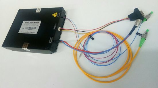
A Raman amplifier is an optical amplifier based on stimulated Raman scattering (SRS). Unlike laser amplifiers such as the EDFA (erbium-doped fibre amplifier), it needs neither a doped gain medium nor population inversion; instead it uses the nonlinear optical effect of ordinary fibre (or another nonlinear medium) itself — as intense pump light travels along the fibre, pump photons transfer part of their energy to signal photons at a lower frequency, and the signal is thereby amplified.
The most distinctive advantage of a Raman amplifier is the flexibility of its amplification wavelength: by changing the pump wavelength, gain can in principle be provided at any wavelength. That lets it cover bands the EDFA cannot reach, such as the S band (1480–1530 nm), and combine with an EDFA to give ultra-broadband amplification.
The performance of a Raman amplifier sets the amplification quality, the transmission distance and the signal-to-noise ratio. In long-haul communication, laser systems and optical sensing it is often what limits the whole system. Only by understanding the underlying physics can the genuinely critical figures be identified during selection.
Compared with an ordinary passive optical component, the defining difference of a Raman amplifier is that it is an active device — it does not passively attenuate the light or change its direction but actively raises the power of the optical signal by drawing energy from an external pump. This ability to amplify actively is exactly what distinguishes an optical amplifier from other optical components.
2. Working principle: how is a Raman amplifier achieved?
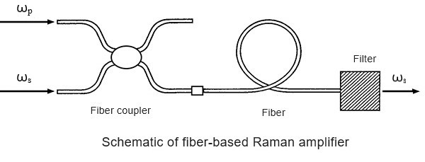
A Raman amplifier has no energy-level structure, and its operation differs from an EDFA in three fundamental ways that determine how it is used in a system.
Point 1: no population inversion, no metastable level, and therefore no energy storage
An EDFA accumulates ions on a metastable level — the pump “charges” the medium and the signal “draws” the energy — and that is how it can store energy. Raman scattering is an instantaneous coupling between the vibrational modes of the fibre and the optical field, and there is no level in the glass that can be filled, so there is nothing to store. The direct consequence is that the gain vanishes the moment the pump is switched off, and the amplifier cannot deliver high peak powers from stored energy the way an EDFA can.
Point 2: the gain is instantaneous — it disappears the moment the pump light disappears
The gain follows the pump power in real time, with no millisecond-scale build-up. The benefit is that the gain can be modulated at high speed, which is useful for pulse shaping; the price is that the intensity noise of the pump is transferred unchanged onto the signal, so a Raman amplifier is extremely demanding about the relative intensity noise (RIN) of its pump and normally needs dedicated noise-reduction circuitry.
Point 3: it works in any ordinary fibre, with no special doped fibre required
Raman gain comes from the molecular vibration of silica itself (about 13 THz) and needs no dopant, so the transmission fibre is the gain medium. This is exactly what makes distributed Raman amplification possible: the pump is launched into tens of kilometres of transmission fibre and the whole length amplifies, so the signal is topped up as it travels and the noise figure can be kept very low. A discrete module instead uses highly nonlinear fibre to shorten the length required.
The physical basis of Raman amplification is stimulated Raman scattering:
1. The Raman scattering phenomenon: as light propagates through a medium, a small fraction of it is scattered inelastically, so that the scattered light has a different frequency from the incident light. The reason is that the photons exchange energy with the vibrational modes of the molecules in the medium (phonons). When a photon loses energy (its frequency falls) the process is called Stokes scattering; when it gains energy (its frequency rises) it is called anti-Stokes scattering. At room temperature Stokes scattering dominates.
2. Stimulated Raman scattering: when intense pump light and weak signal light enter the fibre together and the signal frequency is lower than the pump frequency by exactly one Raman shift (the molecular vibration frequency of the fibre material), the pump transfers energy to the signal efficiently through stimulated Raman scattering, and the signal is amplified.
3. Gain spectrum characteristics: in silica fibre the Raman gain peaks at a wavelength about 100 nm longer than the pump (a frequency shift of about 13 THz). The gain spectrum is broad — roughly 40 THz, or 300 nm — which means a Raman amplifier inherently offers a very wide gain bandwidth.
A useful analogy for the role of a Raman amplifier in a link:
◆ An analogy
If an optical transmission system is a marathon relay race, a Raman amplifier is the “refuelling station” along the route — it does not change the direction of the run (the propagation direction of the light), but it tops up the energy of the tired runners (the attenuated optical signal) so that they can finish the course. The quality of the refuelling station (the noise figure and the gain of the amplifier) determines the final result.
In overall terms the logic of Raman amplification is simple: the pump light scatters in the fibre and hands its energy to signal light one phonon frequency below it, and as long as the pump is strong enough and the interaction length long enough the gain builds up. The price is a very high pump power, which is what makes a Raman system far more involved than an EDFA.
These parameters are coupled: raising the gain usually means more pump power, a wide flat gain needs more pump wavelengths, and excessive pump power introduces unwanted nonlinear effects. A well-designed Raman amplifier is the result of balancing gain, noise, bandwidth and reliability against one another.
3. Key parameters: reading the specifications of a Raman amplifier
◆ The Raman gain equation

The coupled differential equation for Raman gain shows that the rate of change of the signal intensity Is is proportional to the product of the Raman gain coefficient gR, the pump intensity Ip and the signal intensity Is.
In silica fibre the Raman gain coefficient is of the order of 10⁻¹³ m/W, which is why a high pump intensity or a long interaction length is needed.
In practice a few key parameters decide whether a device is suitable. The table below sets out the core specifications of a Raman amplifier:
| Parameter | Meaning | Practical significance |
|---|---|---|
| Raman gain coefficient | The Raman gain per unit length per unit pump power; an intrinsic property of the fibre material, about 1 × 10⁻¹³ m/W for silica fibre at 1550 nm. | Sets how much amplification a given length of fibre can provide; the higher the coefficient, the less fibre length and pump power are needed for a target gain, and the lower the system cost. |
| Raman shift | The frequency offset at which the Raman gain peaks, about 13 THz in silica fibre, corresponding to a wavelength offset of about 100 nm near 1550 nm. | Sets the wavelength spacing between the signal and the pump and is the basic criterion for choosing wavelengths in a Raman amplifier; the shift differs between fibre materials. |
| Gain bandwidth | The effective bandwidth of the Raman gain, about 30–40 nm with a single pump and more than 100 nm of flat gain when several pump wavelengths are combined. | A wide gain bandwidth is the core advantage of a Raman amplifier and supports very large WDM systems; a multi-pump design can shape the gain spectrum to suit a particular band. |
| Pump efficiency | Raman scattering is a comparatively weak nonlinear effect, so the pump efficiency of a Raman amplifier is normally lower than that of an EDFA and a higher pump power is needed. | Directly affects the power consumption and the cost of the system; the low pump efficiency is the main drawback of a Raman amplifier and calls for high-power pump lasers. |
| Polarisation dependence | The Raman gain depends on the polarisation states of the pump and the signal: it is greatest when the two are parallel and least (potentially zero) when they are perpendicular. | Polarisation dependence makes the signal gain fluctuate with the polarisation state and undermines system stability; in practice it is suppressed by polarisation-diverse pumping or polarisation-maintaining fibre. |
| Noise performance | The noise figure of a distributed Raman amplifier can be very low (even effectively negative), because the amplification happens in the transmission fibre itself and the signal is amplified continuously as it travels. | Low noise is the core advantage of distributed Raman amplification; it is equivalent to reducing the effective loss of the fibre and makes the technique indispensable in high-speed long-haul and submarine systems. |
These parameters trade off against one another explicitly: gain efficiency against pump power, gain flatness against the number of pumps, noise performance against polarisation dependence. A single pump is simple but narrow-band, several pumps give ultra-broadband flat gain at the cost of complexity, so no single figure can be used to judge a Raman amplifier.
If some of these parameters are unfamiliar, the Soar Laser product pages carry detailed specifications, and our technical engineers can advise on selection directly.
4. Main types: what kinds of Raman amplifier are there?
A Raman amplifier can be classified along several dimensions, each of which corresponds to a different system trade-off. Here are four ways: by configuration, by pump direction, by number of pumps and by working band.
By configuration
Distributed Raman amplifier (DRA)
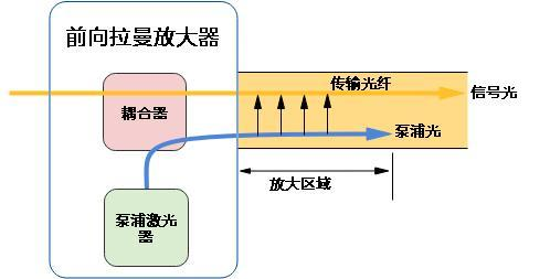
The transmission fibre itself is the gain medium: the pump is launched into the transmission fibre and the signal is amplified continuously as it travels. The advantages are low noise and a weak nonlinear penalty, which suits long-haul transmission.
Discrete Raman amplifier
A dedicated highly nonlinear fibre (such as dispersion-compensating fibre or highly nonlinear fibre) serves as the gain medium in a self-contained amplifier module. The gain is high but so is the noise.
By pump direction
Co-pumping
The pump travels in the same direction as the signal; the noise performance is better.
Counter-pumping
The pump travels in the opposite direction to the signal; this is the most common arrangement.
Bidirectional pumping
Pumping from both ends gives a more uniform gain distribution.
By number of pumps
Single-pump Raman amplifier
A simple structure with a comparatively narrow gain bandwidth.
Multi-pump Raman amplifier
Several pump sources at different wavelengths give an ultra-wide, flat gain spectrum; the ideal choice for WDM systems.
By working band
S-band Raman amplifier
S-band Raman amplifier (1480–1530 nm)
C+L-band Raman amplifier
C+L-band Raman amplifier (1530–1625 nm)
Other bands
The pump wavelength can be chosen freely as required.
Each type has its own advantages and drawbacks, and there is no absolute “best”, only what “fits”. Long-haul trunk transmission normally pairs a distributed Raman amplifier with an EDFA to cut the noise and extend the span; for a special band such as the S band a Raman amplifier is the first choice; and a very large WDM system calls for a multi-pump Raman amplifier to provide ultra-broadband gain.
5. Applications: where is a Raman amplifier used?
Raman amplifiers are used where low noise, wide bandwidth or a special band is required. By main field they fall into the following categories:
- 1. Long-haul fibre communication: a distributed Raman amplifier usually works alongside an EDFA as distributed gain along the span, which lowers the noise figure and extends the reach or raises the capacity. The low-noise advantage matters most in high-speed systems at 100 Gb/s and above.
- 2. Ultra-broadband optical amplification: with several pumps a Raman amplifier can deliver a flat gain bandwidth of 80 nm or more, far wider than a conventional EDFA, which meets the demands of very large WDM systems.
- 3. Amplification in special bands: for bands the EDFA cannot cover (the S band, the O band and so on) a Raman amplifier is an important solution, because the amplification wavelength can be set simply by choosing the pump wavelength.
- 4. Fibre sensing: in distributed fibre sensing such as BOTDR and DTS, Raman amplification can boost the sensing signal and extend the sensing range.
- 5. Laser sources: a Raman amplifier can also form a Raman laser, with mirrors at both ends of the fibre closing a resonator that emits in a special band.
Typical application scenarios
Scenario 1: long-haul fibre communication
A distributed Raman amplifier usually works alongside an EDFA as distributed gain along the span. Because the amplification happens inside the transmission fibre, the signal never decays to a low level before being amplified, and the effective noise figure of the span can improve by 3–5 dB — typically worth 20–30 km of extra reach, or a higher line rate on the same span.
Scenario 2: ultra-broadband optical amplification
With several pumps a Raman amplifier can deliver a flat gain bandwidth of 80 nm or more, far wider than a conventional EDFA. Each pump contributes a gain peak about 13 THz to the long-wavelength side of itself, so a set of pumps spaced across the band sums into a broad, flat profile — the standard way of building an E-band or S-band amplifier.
Scenario 3: amplification in special bands
For bands the EDFA cannot cover (the S band, the O band and so on) a Raman amplifier is an important solution: the gain appears about 13 THz below the pump, so any band can be reached by choosing a pump of the right wavelength, provided a pump laser exists there.
Scenario 4: fibre sensing
In distributed fibre sensing such as BOTDR and DTS the returning scattered light is extremely weak and decays quickly with distance. Raman amplification of that signal, or of the pump that interrogates the fibre, raises the signal-to-noise ratio and extends the sensing range by several kilometres.
Scenario 5: laser sources
A Raman amplifier with mirrors at both ends of the fibre becomes a Raman laser. Because the emission wavelength is set by the pump wavelength plus the Raman shift, it reaches bands where no rare-earth-doped fibre laser exists — which is how 1.2 µm and 1.5 µm Raman fibre lasers are built.
◆ Want to see more real application cases for Raman amplifiers? Visit the application case page of Soar Laser, or contact our technical team directly for professional advice.
6. Common misconceptions
Several fairly widespread but inaccurate beliefs circulate about Raman amplifiers, and they need to be cleared up one by one:
Misconception 1: a Raman amplifier, like an EDFA, works by stimulated emission from doped ions
Not at all. An EDFA amplifies through the energy-level transitions and the stimulated emission of erbium ions and belongs to the laser amplifiers; a Raman amplifier uses the nonlinear optical effect of the fibre material (stimulated Raman scattering), needs no dopant and knows nothing of population inversion.
Misconception 2: the gain bandwidth of a Raman amplifier is fixed
The gain wavelength of a Raman amplifier is set entirely by the pump wavelength, so in principle gain can be provided at any wavelength — one of its greatest strengths. Combining several pump wavelengths also allows the bandwidth and the flatness to be designed to order.
Misconception 3: Raman amplifiers are noisy
A discrete Raman amplifier can indeed be comparatively noisy, but a distributed Raman amplifier, which uses the transmission fibre itself, can have a very low noise figure — better even than an EDFA. The signal is amplified continuously as it travels, so the signal-to-noise ratio is never degraded by decaying first and being amplified afterwards.
Misconception 4: a Raman amplifier can replace an EDFA
The two are complementary rather than alternatives. An EDFA offers high gain, high efficiency and low cost and is the mainstream choice; a Raman amplifier offers flexible bandwidth and low noise in distributed form but demands a high pump power and costs more. Long-haul systems in practice use a hybrid of EDFA plus distributed Raman amplification.
The misconceptions about Raman amplifiers go well beyond these. Pump schemes, fibre designs and noise optimisation change every year, so earlier rules of thumb may no longer hold. If you have other questions, leave a comment and we will answer them one by one.
◆ Recommended reading
- What Is a Fibre Amplifier? EDFA Is Only One of Them
- What Is an EDFA? The Signal Refuelling Station of Fibre Communication
- What Is Gain? How the Amplification Capability of an Optical Amplifier Is Measured
- What Is an Optical Amplifier? Amplifying a Weak Optical Signal Directly
- What Is a Noise Figure? Why an Amplifier Adds Noise
Leave a Reply