


What Is an EDFA? The Signal Refuelling Station of Fibre Communication
You may often hear the term EDFA, but what exactly is it? What role does it play in a system, and how does it differ from other similar technologies? This article works from the underlying physics through to the engineering application and sets out the mechanism, the key parameters, the main types and the practical applications of the EDFA.
Table of contents
- 1. What is an EDFA? Getting the core concept straight
- 2. Working principle: how is an EDFA achieved
- 3. Key parameters: reading the specifications of an EDFA
- 4. Main types: what kinds of EDFA are there
- 5. Applications: where is an EDFA used?
- 6. Common misconceptions: pitfalls to avoid
1. Core concept: what is an EDFA?
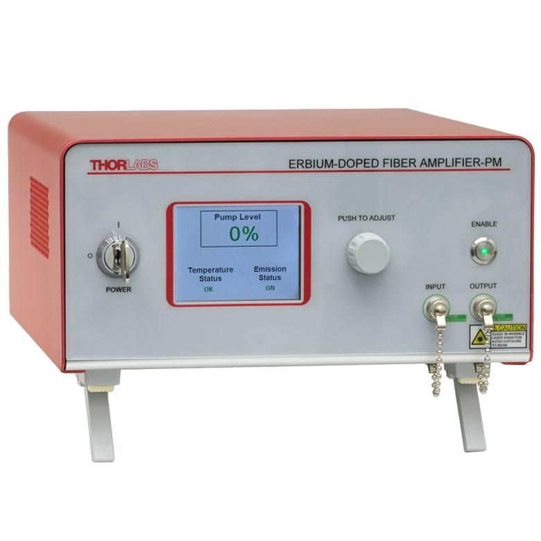
The first reaction to the term EDFA is often that it sounds highly specialised. But anyone familiar with lasers knows that it is one of the most fundamental concepts in the field. An erbium-doped fibre amplifier (Erbium-doped Fibre Amplifier, EDFA for short) is the most important and most widely applied type of fibre amplifier. Its core is a length of special fibre doped with erbium ions (Er³⁺) serving as the gain medium; pump light raises the erbium ions to a higher energy level, and stimulated emission then amplifies the signal in the 1550 nm band (the C band and the L band of fibre communication).
The invention of the EDFA was a decisive breakthrough in the history of optical communication and made the large-scale commercial deployment of long-haul fibre systems and wavelength division multiplexing (WDM) possible. Before it, long-distance optical links needed optical-electrical-optical regeneration every few tens of kilometres, at high cost and limited capacity. The EDFA made all-optical amplification a reality, so that a single fibre could amplify signals at many wavelengths at once, which greatly increased the capacity of a fibre.
The performance of an EDFA sets the amplification quality, the transmission distance and the signal-to-noise ratio. In long-haul communication, laser systems and optical sensing, the EDFA is often what limits the performance of the whole system. Understanding the underlying physics is what lets the key figures be picked out during selection.
Compared with an ordinary optical component or an ordinary light source, the distinguishing feature of an EDFA is how deliberately it acts — it does not merely let light pass through, it takes an active part in the generation, amplification or modulation of that light. This active role is precisely why a laser can do things ordinary light cannot.
2. Working principle: how is an EDFA achieved?
The working principle of an EDFA breaks down into three steps that follow one another.
The operation of an EDFA rests on the three-level or quasi-three-level system of the erbium ion:
1. Pumping: the pump light (usually at 980 nm or 1480 nm) raises the erbium ions from the ground state (the ⁴I₁₅/₂ level) to a higher level. A 980 nm pump lifts the ions to the ⁴I₁₁/₂ level, from which they decay rapidly and non-radiatively to the metastable ⁴I₁₃/₂ state; a 1480 nm pump raises the ions straight to the metastable state.
2. Population inversion: once enough erbium ions sit in the metastable state, a population inversion is formed — more particles in the upper level than in the lower level. This is the precondition for optical amplification.
3. Amplification by stimulated emission: when signal light around 1550 nm passes through the erbium-doped fibre, a signal photon stimulates an erbium ion in the metastable state to fall back to the ground state, releasing a photon identical to it in frequency, phase and direction, and the signal is thereby amplified.
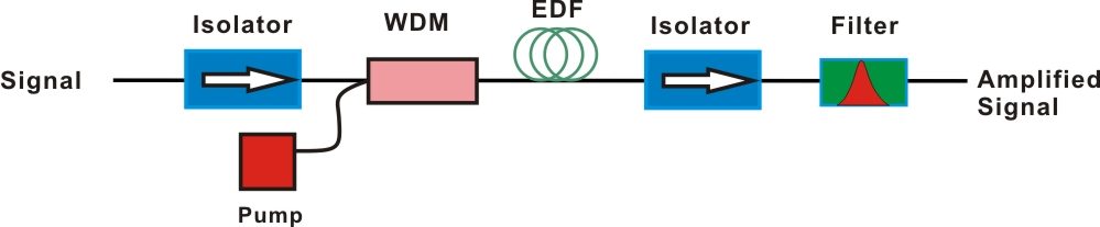
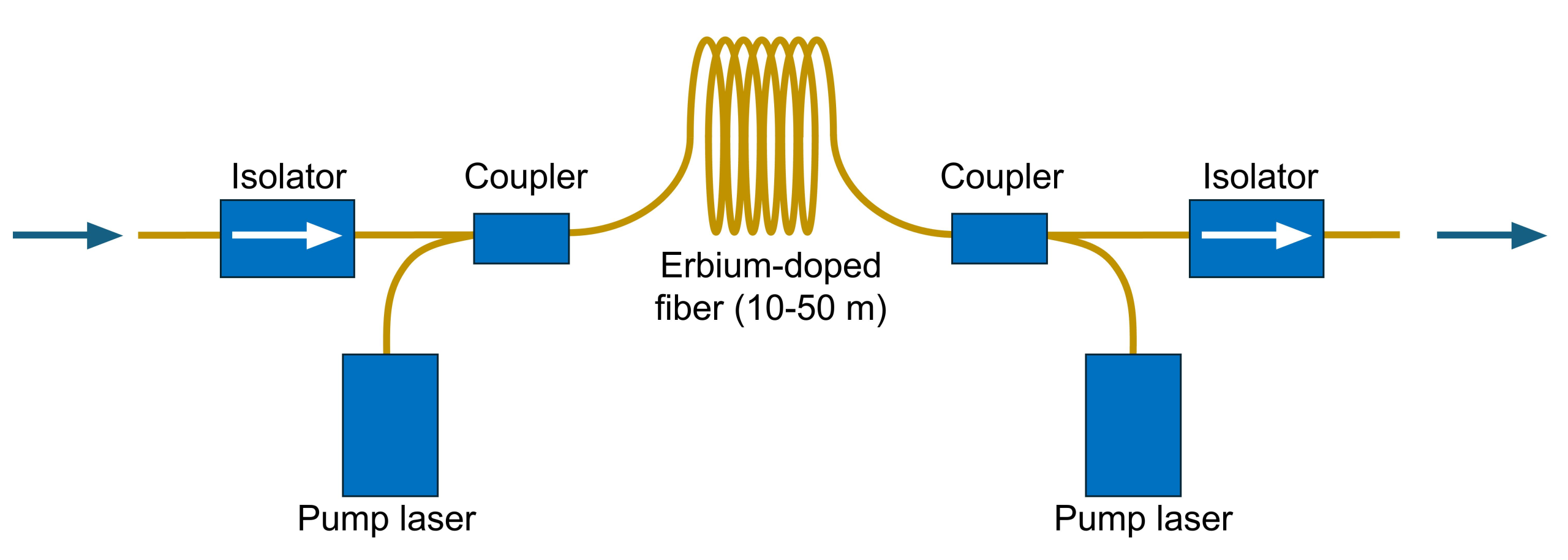
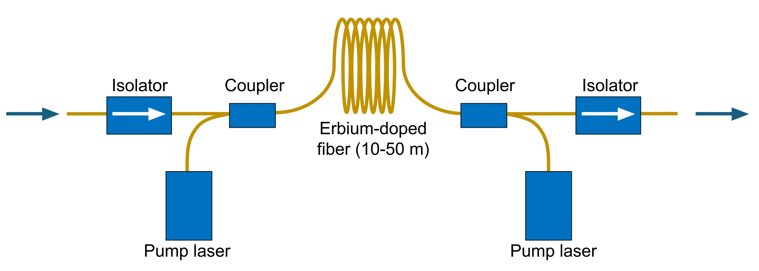
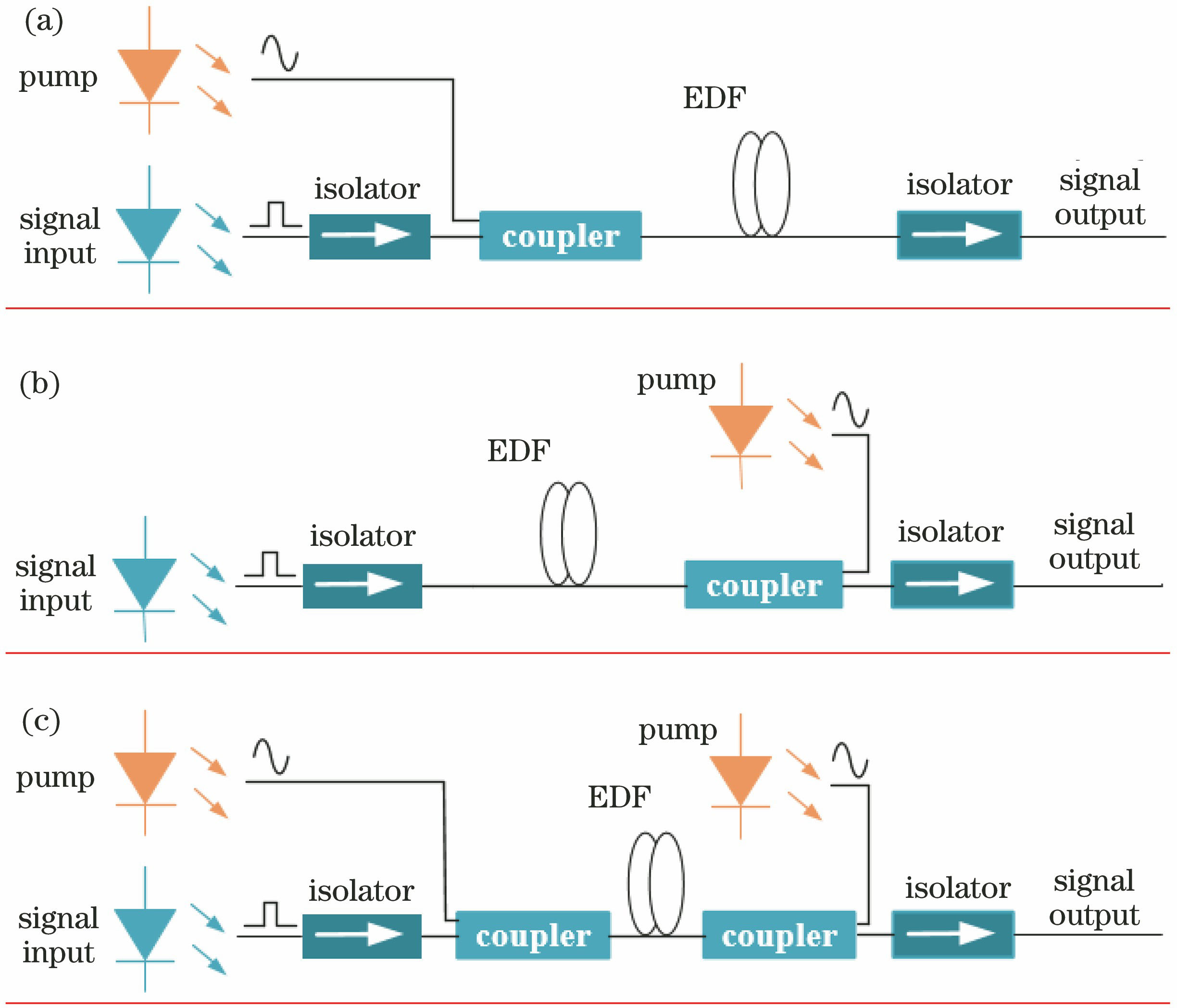
The typical structure of an EDFA comprises the input fibre, an input isolator, a wavelength division multiplexer (which combines the pump light with the signal light), the erbium-doped fibre (the gain medium), the pump laser, an output isolator and the output fibre. The isolators prevent back-propagating light (such as reflections and reverse-traveling ASE (amplified spontaneous emission)) from affecting the stability and the noise performance of the amplifier.
There are three pumping arrangements: co-pumping (the pump light travels in the same direction as the signal), counter-pumping (opposite direction) and bidirectional pumping. Co-pumping gives the lowest noise, counter-pumping the highest output power, and bidirectional pumping combines the two.
◆ An analogy
If an optical transmission system is a marathon relay race, an EDFA is the “refuelling station” along the route — it does not change the direction of the run (the propagation direction of the light), but it tops up the energy of the tired runners (the attenuated optical signal) so that they can finish the course. The quality of the refuelling station (the noise figure and the gain of the amplifier) determines the final result.
In overall terms the logic of an EDFA is not complicated: the pump light lifts the erbium ions into the metastable state, and the signal light takes that energy back in the form of new photons that are exactly in step with it. The signal grows stronger, and all of the noise introduced comes from spontaneous emission in the amplification process.
The parameters of an EDFA are also interdependent. Raising the gain usually brings more noise, widening the bandwidth lowers the gain efficiency, and pushing the output power into saturation compresses the gain. A performance-competent EDFA is the result of balancing gain, noise, bandwidth and output power against one another.
3. Key parameters: reading the specifications of an EDFA
◆ Gain formula

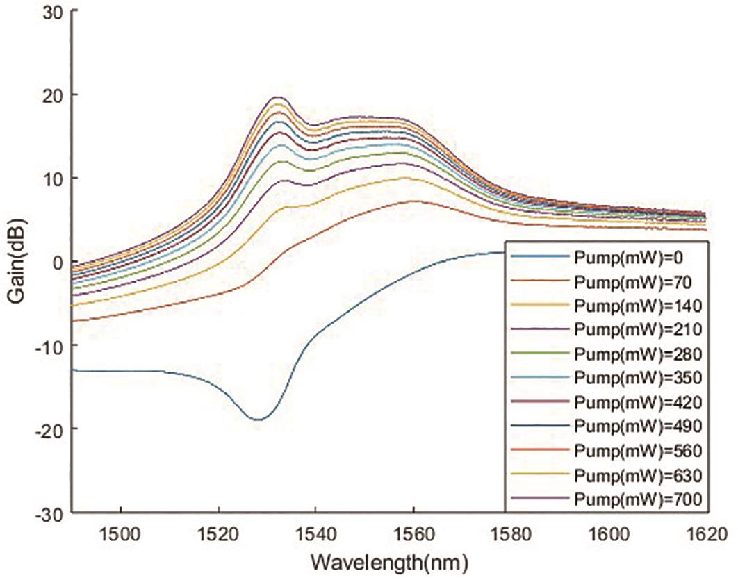
The gain of an EDFA is usually expressed in decibels (dB): G(dB) = 10 × log₁₀(Pout/Pin).
A gain of 20 dB means the signal power is multiplied by 100, and 30 dB by 1000. The small-signal gain of a typical EDFA is 20–40 dB.
In practice a few key parameters decide whether a device is suitable. The table below sets out the core specifications of an EDFA and what each one means:
| Parameter | Meaning | Practical significance |
|---|---|---|
| Small-signal gain | The gain when the input signal is very weak, typically 20–40 dB for a single stage and higher for multi-stage amplifiers, in decibels (dB). | Sets how far a weak signal can be boosted and is the core figure for a preamplifier; insufficient gain lets the signal drown in the noise, while multi-stage amplification reaches higher gain at the cost of accumulated ASE noise. |
| Saturated output power | The output power at which the gain has fallen by 3 dB, typically 10–23 dBm (10 mW – 200 mW) for a commercial EDFA and above 30 dBm (1 W) for a high-power model. | Sets the maximum output capability of the EDFA and is the key figure for a power amplifier; it directly determines how far the system can reach and how well it drives the following device. |
| Noise figure (NF) | A measure of the noise the amplifier introduces, in dB; a high-quality EDFA can approach the theoretical limit of 3 dB and typically sits at 4–6 dB, with co-pumping at 980 nm giving the best noise performance. | Determines the final signal-to-noise ratio and the achievable distance, and it matters most for a preamplifier; the lower the NF, the higher the receive sensitivity and the longer the system can run. |
| Gain bandwidth | The natural gain bandwidth of an EDFA is about 30–40 nm, covering the C band (1530–1565 nm) and part of the L band (1565–1625 nm). | Determines how many WDM channels the EDFA can handle at once; the roughly 35 nm of the C band accommodates more than 80 channels at 100 GHz spacing, which is what underpins wavelength division multiplexed systems. |
| Gain flatness | The largest ripple in the gain across the specified bandwidth, in dB; in a WDM system the gain difference between channels is normally required to be below 1 dB. | Decides how consistent the power and the signal-to-noise ratio are from channel to channel; the poorer the flatness, the larger the power spread between channels and the greater the impact on system capacity and stability. |
| Pump efficiency | The ratio of the increase in optical output power to the pump optical power; 980 nm pumping is normally more efficient than 1480 nm pumping, and this is the measure of energy conversion efficiency. | Affects the power consumption, the cost and the thermal design of the EDFA; the higher the efficiency, the less pump power is needed to reach a given gain and output power and the lower the running cost. |
These parameters involve clear trade-offs: 980 nm pumping has lower noise but a limited output power per pump diode, while 1480 nm pumping offers more power at the cost of slightly worse noise, and bidirectional pumping balances the two. No single figure can therefore be used to judge an EDFA.
If some of these parameters are unfamiliar, the Soar Laser product pages carry detailed specifications, and our technical engineers can advise on selection directly.
4. Main types: what kinds of EDFA are there?
An EDFA can be classified along several dimensions, each of which corresponds to a different engineering trade-off. Here are four ways of classifying them, by application, by pump wavelength, by structure and by working band.
By application
Booster amplifier
Placed after the transmitter, it amplifies several WDM signals together to a high power, where a high output power is the key figure
Line amplifier (in-line amplifier)
Placed mid-span in the fibre link to compensate the transmission loss, where gain and noise have to be balanced
Preamplifier
Placed ahead of the receiver to amplify a weak signal and raise the receive sensitivity, where low noise is the key figure
By pump wavelength
980 nm pumped EDFA
A low noise figure and high efficiency; the most widely used arrangement
1480 nm pumped EDFA
A higher pump power is possible, which suits situations that need a high output power
By structure
Single-stage EDFA
A simple structure with comparatively low gain
Multi-stage EDFA
Two or three stages in cascade, with gain flattening filters or dispersion compensation modules inserted between them; high gain and good performance
By working band
C-band EDFA
1530–1565 nm, the most commonly used
L-band EDFA
1565–1625 nm, with slightly lower gain, used to extend capacity
C+L band EDFA
Covering both bands at once, for ultra-broadband amplification
Each type has its own advantages and drawbacks, and there is no absolute “best”, only what “fits”. A long-haul trunk link calls for a line amplifier that balances gain against noise; boosting the launch power calls for a booster with a high output power; amplifying ahead of the receiver calls for a preamplifier with a low noise figure. The weighting of the parameters differs completely between them.
5. Applications: where is an EDFA used?
The applications of EDFAs are very wide, from communication networks to fibre sensing, from test and measurement to high-power lasers; wherever an optical signal has to be carried further or made stronger, an EDFA is involved. By main field they fall into the following categories:
- 1. Long-haul fibre communication: the principal application of the EDFA. In transoceanic cables and long-haul backbone networks, an EDFA line amplifier is needed every 80–120 km to compensate the fibre loss, so a link of several thousand kilometres requires several dozen EDFAs in cascade. Each stage adds its own ASE noise to the signal, so the link design is bounded by the OSNR budget: the more stages are cascaded, the lower the gain per stage has to be, or the accumulated noise drowns the signal. This is what forces an EDFA to combine a low noise figure with a sufficient output power.
- 2. Wavelength division multiplexing (WDM) systems: an EDFA amplifies many wavelength channels at once (dozens to hundreds), which makes it the core device of a DWDM system. The difficulty is that the erbium ion does not give a flat gain across wavelengths; the ripple within the C band can reach several dB, and without correction the OSNR of the individual channels differs noticeably. Gain flattening techniques such as long-period gratings or ring-cavity filters exist precisely to flatten this curve.
- 3. Metropolitan and access networks: in metropolitan optical networks and FTTX systems, EDFAs provide signal power compensation in the optical distribution network (ODN), for instance in CATV transmission. These links are short but heavily branched with large insertion losses, so cost and power consumption matter more than absolute performance, and a compact structure with high pump efficiency is normally chosen.
- 4. Fibre sensing: in distributed fibre sensing systems, an EDFA amplifies the backscattered signal (Rayleigh or Brillouin scattering) returning along the fibre. Such a signal is extremely weak to begin with and decays rapidly with distance, so placing the EDFA ahead of the detector raises the signal-to-noise ratio markedly, which extends the sensing range and improves the resolution.
- 5. Test and measurement: optical test instruments commonly use an EDFA either to raise the output power of a source or as a preamplifier ahead of a weak-signal detector. The first use calls for a stable output power and for the noise contribution to the signal under test to be small; the second places more weight on a low noise figure, because the signal under test is often already close to the noise floor of the instrument itself.
Typical application scenarios
Scenario 1: long-haul fibre communication
This is the principal application of the EDFA. In transoceanic cables and long-haul backbone networks, an EDFA line amplifier is needed every 80–120 km to compensate the fibre loss, so a link of several thousand kilometres requires several dozen EDFAs in cascade. Each stage adds its own ASE noise to the signal, so the link design is bounded by the OSNR budget: the more stages are cascaded, the lower the gain per stage has to be, or the accumulated noise drowns the signal. This is what forces an EDFA to combine a low noise figure with a sufficient output power.
Scenario 2: wavelength division multiplexing (WDM) systems
An EDFA amplifies many wavelength channels at once (dozens to hundreds), which makes it the core device of a DWDM system. The difficulty is that the erbium ion does not give a flat gain across wavelengths; the ripple within the C band can reach several dB, and without correction the OSNR of the individual channels differs noticeably. Gain flattening techniques such as long-period gratings or ring-cavity filters exist precisely to flatten this curve.
Scenario 3: metropolitan and access networks
In metropolitan optical networks and FTTX systems, EDFAs provide signal power compensation in the optical distribution network (ODN), for instance in CATV transmission. These links are short but heavily branched with large insertion losses, so cost and power consumption matter more than absolute performance, and a compact structure with high pump efficiency is normally chosen.
Scenario 4: fibre sensing
In distributed fibre sensing systems, an EDFA amplifies the backscattered signal (Rayleigh or Brillouin scattering) returning along the fibre. Such a signal is extremely weak to begin with and decays rapidly with distance, so placing the EDFA ahead of the detector raises the signal-to-noise ratio markedly, which extends the sensing range and improves the resolution.
Scenario 5: test and measurement
Optical test instruments commonly use an EDFA either to raise the output power of a source or as a preamplifier ahead of a weak-signal detector. The first use calls for a stable output power and for the noise contribution to the signal under test to be small; the second places more weight on a low noise figure, because the signal under test is often already close to the noise floor of the instrument itself.
◆ Want to see more real application cases for EDFAs? Visit the application case page of Soar Laser, or contact our technical team directly for professional advice.
6. Common misconceptions
A few fairly widespread but inaccurate beliefs circulate about EDFAs, and they need to be cleared up one by one:
Misconception 1: an EDFA can amplify light at any wavelength
An EDFA amplifies only light in roughly the 1530–1625 nm range, as determined by the energy level structure of the erbium ion. The gain peaks around 1550 nm and falls away sharply outside that range. Amplifying other bands requires a fibre amplifier with a different dopant.
Misconception 2: the more EDFAs are cascaded, the better the signal quality
Every EDFA the signal passes through adds extra ASE noise. After several stages the noise keeps accumulating until the signal-to-noise ratio falls to an unacceptable level. The number of EDFAs in a long-haul link therefore has to be designed against the OSNR budget of the system; more is not better.
Misconception 3: 980 nm and 1480 nm pumping can be swapped freely
The two pump wavelengths each have their own characteristics. A 980 nm pump gives a lower noise figure and a higher pump efficiency, but the power per pump diode is limited; a 1480 nm pump can supply more pump power, which suits high-power applications, at the cost of a slightly worse noise figure. Which pump to use depends on the requirements of the application.
Misconception 4: the higher the EDFA gain, the better
An excessive gain brings serious ASE problems: ASE not only consumes energy from the gain medium, reducing the effective signal gain, but also introduces a great deal of noise. In practice gain and noise have to be balanced, and it is sometimes better to give up a little gain in exchange for better noise performance.
The misconceptions about EDFAs go well beyond these. The technology develops quickly and the choice of pump wavelength, the gain flattening approach and the noise optimisation strategy are all still improving, so earlier rules of thumb may no longer hold. If you have other questions, leave a comment and we will answer them one by one.
◆ Recommended reading
- What is an optical amplifier? Amplifying a weak optical signal directly
- What is a fibre amplifier? EDFA is only one of them
- What is ASE? Where the noise light in an amplifier comes from
- What is gain saturation? Why an amplifier cannot amplify indefinitely
- What is a Raman amplifier? The optical amplifier that uses a scattering effect
Leave a Reply