


What Is an SOA? The Principle and Characteristics of a Semiconductor Optical Amplifier
A semiconductor optical amplifier (SOA) is an optical amplifier whose gain comes from a semiconductor material. Its compact size, electrical pumping, fast response and ease of integration are its distinctive strengths. Beyond simple amplification, the fast gain dynamics of an SOA give it an irreplaceable role in optical signal processing. This article covers the principle, the parameters, the types and the applications of the SOA.
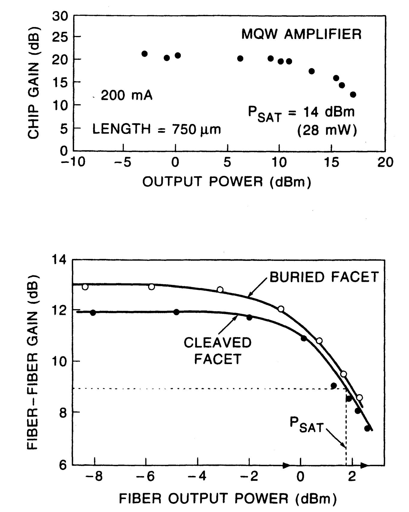
Table of contents
- 1. What is an SOA? Getting the core concept straight
- 2. Working principle: how is an SOA achieved
- 3. Key parameters: reading the specifications of an SOA
- 4. Main types: what kinds of SOA are there
- 5. Applications: where is an SOA used
- 6. Common misconceptions: points easily confused
1. Core concept: what is an SOA?
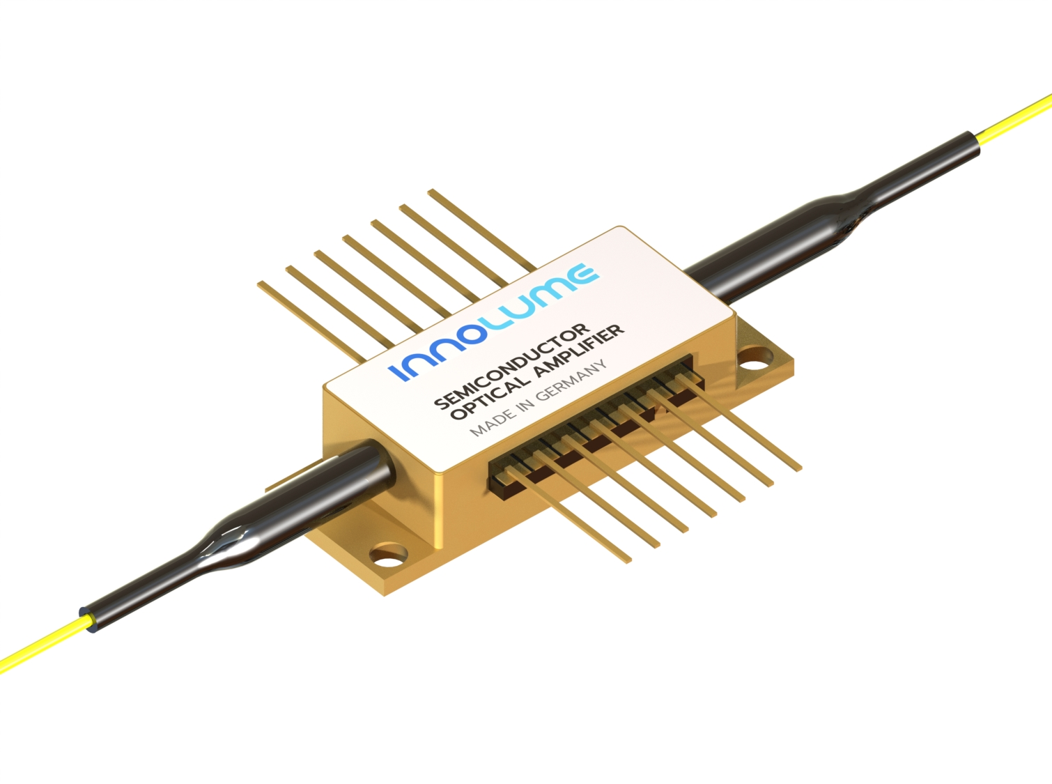
A semiconductor optical amplifier (SOA) is an optical amplifier that uses gain in a semiconductor material. In simple terms it can be understood as a semiconductor laser without a resonator: inside a semiconductor waveguide, current injection (electrical pumping) produces a population inversion, and an optical signal passing through that gain waveguide is amplified by stimulated emission.
The defining strengths of an SOA are its small size, electrical pumping and ease of integration. Compared with a fibre amplifier, its gain recovery time is extremely short — of the order of nanoseconds — which makes it useful not only for amplifying a signal but also as a signal-processing device such as an optical switch or a wavelength converter.
The performance of an SOA sets the amplification quality, the transmission distance and the signal-to-noise ratio; in short-reach optical communication, optical signal processing and photonic integration it is often what limits the whole system. Only by understanding the underlying physics can the genuinely critical figures be identified during selection.
Compared with an ordinary passive optical component, the defining difference of an SOA is that it is an active device — it does not passively attenuate the light or change its direction but actively raises the power of the optical signal by drawing energy from an external pump. This ability to amplify actively is exactly what distinguishes an optical amplifier from other optical components.
2. Working principle: how is an SOA achieved?
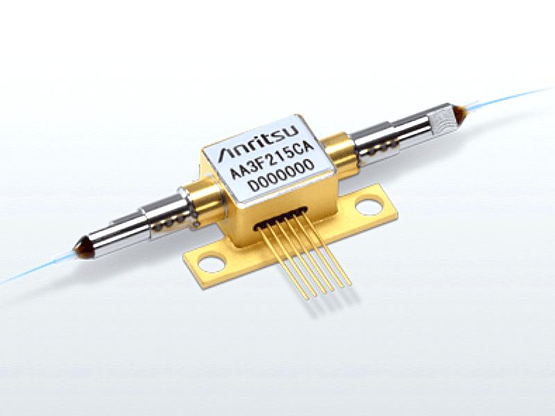
An SOA and a semiconductor laser share the same origin: both rely on stimulated emission in a semiconductor material. The essential difference is that a laser has a resonator in which oscillation builds up, whereas an SOA deliberately suppresses reflection and performs a single pass of amplification.
There are three levels at which to understand how an SOA works:
Level one: the basic amplification mechanism — stimulated emission
Like any optical amplifier, an SOA amplifies by stimulated emission; the only difference is that the gain medium is a semiconductor:
1. Electrical pumping and population inversion: a forward current is injected across the semiconductor PN junction, electrons entering the active region from the N side and holes from the P side. Once the injection current exceeds the threshold, the electron concentration in the conduction band and the hole concentration in the valence band of the active region exceed their equilibrium values, forming a population inversion — the precondition for optical gain.
2. Amplification by stimulated emission: when the input signal passes through the active waveguide, a signal photon drives an electron in the conduction band down to the valence band, where it recombines with a hole and releases a photon with the same frequency, the same phase and the same direction as the signal photon, and the signal is amplified.
Level two: the central difficulty of an SOA — suppressing facet reflection (so that it does not turn into a laser)
An SOA looks much like a semiconductor laser but differs in one essential respect: an SOA must have no resonator and must not lase. The cleaved facets of a semiconductor material naturally reflect about 32 %, and left untreated the two facets would form a resonator and the SOA would become a laser.
Suppressing facet reflection is therefore the first priority in SOA design. There are three common techniques:
| Technique | Principle | Effect |
|---|---|---|
| Anti-reflection coating (AR coating) | A multilayer anti-reflection coating is deposited on the facets and cancels the reflected light by thin-film interference | Reduces the facet reflectivity from 32 % to 10⁻⁴ or even lower |
| Angled waveguide (angled facet) | The waveguide meets the facet at an angle (typically 7°–15°), so that the reflected light does not travel back along the waveguide | Combined with an AR coating it gives an extremely low effective reflectivity (of the order of 10⁻⁵) |
| Buried heterostructure (BH) | The active region is buried in a wide-bandgap material that confines both the optical field and the carriers, and the field strength at the facet is reduced, which lowers the effective reflectivity | Lowers the effective facet reflectivity further and improves the beam quality and the temperature behaviour |
A commercial SOA normally uses several techniques at once — AR coating, angled waveguide and buried structure — to suppress facet reflection far enough for stable travelling-wave amplification without oscillation.
Level three: gain dynamics — the high-speed behaviour unique to an SOA
The carrier lifetime in an SOA is very short (about 0.1–1 ns), which means the gain recovers extremely quickly. That behaviour cuts both ways:
The upside: the gain responds quickly, which enables high-speed optical signal processing such as all-optical switching, wavelength conversion, optical logic gates and 3R regeneration; the SOA is a key device of all-optical networks.
The downside: a high-speed signal suffers a pronounced pattern effect — each bit receives a different gain depending on how deeply the preceding bits saturated the amplifier, so the output amplitude is uneven. Above 10 Gb/s the pattern effect is suppressed by injecting an assist light or by gain clamping.
◆ An analogy
If an optical transmission system is a marathon relay race, an SOA is the “refuelling station” along the route — it does not change the direction of the run (the propagation direction of the light), but it tops up the energy of the tired runners (the attenuated optical signal) so that they can finish the course. The quality of the refuelling station (the noise figure and the gain of the amplifier) determines the final result.
In one sentence, the logic of an SOA is this: the current floods the active region with carriers and creates a population inversion, and a signal photon passing through copies itself by stimulated emission. Facet reflection is held below 10⁻⁴, so the device amplifies without oscillating; the carrier lifetime is only nanoseconds, so the gain can be modulated by the signal itself. The first makes it an amplifier, the second makes it a signal-processing device.
These parameters are coupled: raising the gain means more injection current, and more current brings more spontaneous-emission noise; widening the gain spectrum means changing the composition of the active region, usually at the cost of peak gain; and pushing the output into saturation makes the pattern effect markedly worse. A serviceable SOA is the result of balancing gain, noise, bandwidth and polarisation dependence against one another.
3. Key parameters: reading the specifications of an SOA
In practice a few key parameters decide whether a device is suitable. The table below sets out the core specifications of an SOA:
| Parameter | Meaning | Practical significance |
|---|---|---|
| Small-signal gain | The gain when the input signal is very weak, typically 20–30 dB — comparable to or slightly below an EDFA — depending on the injection current and the active-region structure. | Sets the ability of the SOA to amplify a weak signal and is the basic figure for signal processing and short-reach communication; insufficient gain limits the reach of the system. |
| Saturated output power | The output power at which the gain has fallen by 3 dB, typically around 10 dBm (10 mW) for a standard SOA, far below an EDFA. | Sets the maximum output capability of the SOA; the low saturation power is its main disadvantage against an EDFA and limits its use as a power amplifier. |
| Noise figure (NF) | The noise figure of an SOA is typically 6–10 dB, clearly higher than the 4–6 dB of an EDFA, and is dominated by carrier recombination noise and spontaneous emission. | Directly affects the output signal-to-noise ratio; the high noise figure restricts cascading in long-haul systems and makes the SOA better suited to signal processing. |
| Gain bandwidth | The gain bandwidth of an SOA is wide, from tens of nanometres to more than a hundred, depending on the semiconductor material system, and can cover the O band through to the L band. | A wide gain bandwidth lets an SOA amplify many wavelengths at once and supports multi-band signal processing; it is an important basis for all-optical switching and wavelength conversion. |
| Polarisation-dependent gain (PDG) | The gain of a standard SOA depends strongly on the input polarisation, with a difference of several dB between the TE and TM modes; special structures can reduce it. | Polarisation dependence is an inherent drawback of the SOA and makes the signal power fluctuate with the polarisation state; in communication systems it is suppressed by polarisation diversity or strained-layer structures. |
| Gain recovery time | The gain recovery time of an SOA is extremely short, typically a few hundred picoseconds to a few nanoseconds, far faster than the milliseconds of a fibre amplifier. | The very short recovery time is the core advantage of the SOA and enables high-speed all-optical signal processing such as all-optical switching, wavelength conversion and signal regeneration. |
These parameters involve clear trade-offs: high gain usually brings more noise and a stronger pattern effect, a wideband design needs special materials and structures, and polarisation dependence has to be pressed down by strain compensation or polarisation diversity. No single figure can therefore be used to judge an SOA.
If some of these parameters are unfamiliar, the Soar Laser product pages carry detailed specifications, and our technical engineers can advise on selection directly.
4. Main types: what kinds of SOA are there?
An SOA can be classified along several dimensions, each of which corresponds to a different engineering trade-off. Here are four ways: by structure, by output power, by special structure and by function.
By structure
Fabry–Pérot SOA (FP-SOA)
The simplest structure, but facet reflection has a strong influence and the gain spectrum shows pronounced ripple
Travelling-wave SOA (TW-SOA)
AR coatings and angled facets reduce the reflection sharply, giving a flat gain spectrum; the most widely used type
By output power
Standard SOA
An output power of about 10 dBm, used for small-signal amplification and optical signal processing
Tapered amplifier
The waveguide widens progressively so that the output power can reach several watts, for applications that need more power
By special structure
Vertical-cavity SOA (VCSOA)
A VCSEL-like structure with the gain provided along the vertical direction, suited to arrays and low-cost applications
Quantum-dot SOA
Quantum dots form the active region, giving a wider gain spectrum, lower noise and better temperature stability
By function
Linear amplifier
Used to amplify the power of an optical signal
Optical switch
Uses gain saturation to switch at high speed
Wavelength converter
Uses cross-gain modulation (XGM) or cross-phase modulation (XPM)
Signal regenerator
Reshapes and re-amplifies a degraded optical signal
Each type has its own advantages and drawbacks, and there is no absolute “best”, only what “fits”. For long-haul trunk transmission an EDFA has the edge on noise and power; for compact, low-cost metropolitan amplification, or where optical switching and wavelength conversion are needed, an SOA is the better choice. A tapered SOA suits applications that call for a higher output power.
5. Applications: where is an SOA used?
SOAs are used where compactness, electrical pumping or a fast gain response is required. By main field they fall into the following categories:
- Signal amplification in optical communication: in metropolitan and access networks an SOA serves as a low-cost optical amplifier, especially where a compact size and low power consumption matter.
- Optical signal processing: the most distinctive application area of the SOA. Its fast gain dynamics and nonlinear effects allow:
- wavelength conversion: moving a signal from one wavelength to another for optical switching networks
- optical switching: nanosecond switching by gain saturation
- signal regeneration: 3R regeneration (re-amplifying, reshaping and retiming) of a degraded signal
- all-optical logic gates: AND, OR and NOT operations performed entirely in the optical domain
- Pulse amplification: in pulse amplification applications that need a compact footprint, an SOA can serve as the gain medium.
- Sensing: in fibre sensing and optical detection systems an SOA can act as a low-cost preamplifier.
- Photonic integrated circuits (PIC): an SOA can be integrated on the same chip as other semiconductor photonic devices (lasers, modulators, detectors), which makes it a key building block of photonic integrated circuits.
Typical application scenarios
Scenario 1: signal amplification in optical communication
In metropolitan and access networks an SOA serves as a low-cost optical amplifier, especially where a compact size and low power consumption matter. It also fills a slot the EDFA cannot: the 1310 nm window. An EDFA works only above 1530 nm, whereas an SOA covers the O band around 1300 nm — the low-dispersion window of short-reach data-centre links and of older metropolitan fibre. A single device gives 20–30 dB of gain, but a 6–10 dB noise figure limits cascading to two or three stages.
Scenario 2: optical signal processing
This is the most distinctive application of the SOA and the part a fibre amplifier cannot replace. With a carrier lifetime of only 0.1–1 ns the gain can follow the signal bit by bit, so the signal light can not only be amplified but can also modulate another beam — which is where cross-gain modulation (XGM), cross-phase modulation (XPM) and four-wave mixing (FWM) all come from. All-optical wavelength converters, switches, logic gates and 3R regenerators are built on that single physical basis.
Scenario 3: wavelength conversion
The information is moved from one wavelength to another, for wavelength reuse and blocking resolution in optical switching networks. The usual approach is XGM: a continuous probe beam enters the SOA together with the signal; a “1” bit consumes carriers and depresses the gain while a “0” bit lets it recover, so the probe is copied in inverted form onto the new wavelength. The scheme is simple and efficient and works beyond 40 Gb/s; the drawbacks are a degraded extinction ratio and inverted logic.
Scenario 4: optical switching
Gain saturation gives nanosecond switching: a control beam depresses the gain of the SOA and the signal passing through is switched off; when the control beam is removed the gain recovers and the signal passes again. The switching time is set by the carrier lifetime, typically below 1 ns, and the extinction ratio can exceed 40 dB — far faster than mechanical switches based on MEMS or liquid crystals. It suits optical packet and burst switching, at the cost of inter-channel crosstalk caused by gain saturation.
Scenario 5: signal regeneration
3R regeneration (re-amplifying, reshaping, retiming) of a degraded signal. Amplification alone cannot remove accumulated noise and jitter; the signal has to pass through a nonlinear decision stage that rebuilds it. There are two ways to use an SOA: gain saturation provides amplitude equalisation for 2R reshaping, or two SOAs are combined in a Mach–Zehnder interferometer (SOA-MZI) so that cross-phase modulation delivers 3R regeneration with clock recovery. The latter is one of the most mature all-optical regeneration schemes.
◆ Want to see more real application cases for SOAs? Visit the application case page of Soar Laser, or contact our technical team directly for professional advice.
6. Common misconceptions
Several fairly widespread but inaccurate beliefs circulate about SOAs, and they need to be cleared up one by one:
Misconception 1: an SOA and an EDFA perform much the same and can be swapped
They differ substantially. An EDFA offers high output power, low noise and no polarisation dependence, but is bulky and needs optical pumping; an SOA is compact, electrically pumped, easy to integrate and fast, but has a low output power, high noise and strong polarisation dependence. Both the applications and the specifications differ enough that the two cannot simply be interchanged.
Misconception 2: an SOA can only amplify an optical signal
Amplification is only one of its basic functions. Because of its ultrafast gain dynamics and rich nonlinear effects, an SOA is more often used as a signal-processing device — a wavelength converter, an optical switch, an all-optical logic gate — which is precisely what a fibre amplifier struggles to do.
Misconception 3: the gain of an SOA does not depend on polarisation
A standard SOA is strongly polarisation dependent, and the gain of the TE and TM modes can differ by several dB; this is inherent to the semiconductor material. Only a specially designed device, such as a strain-compensated quantum well, achieves a low polarisation-dependent gain, and the difference has to be checked carefully at selection.
Misconception 4: the faster the gain recovery of an SOA, the better
Fast gain recovery cuts both ways. For signal processing such as wavelength conversion it is an advantage; for amplifying a high-speed digital signal it produces a severe pattern effect — consecutive “1” bits fall in amplitude bit by bit as the gain saturates, and the signal is distorted. This is one reason an SOA is unsuited to high-speed long-haul transmission.
The misconceptions about SOAs go well beyond these. Quantum dots, buried heterostructures and polarisation compensation improve every year, so earlier rules of thumb may no longer hold. If you have other questions, leave a comment and we will answer them one by one.
◆ Recommended reading
- What Is an Optical Amplifier? Amplifying a Weak Optical Signal Directly
- What Is an EDFA? The Signal Refuelling Station of Fibre Communication
- What Is Gain? How the Amplification Capability of an Optical Amplifier Is Measured
- What Is Gain Saturation? Why an Amplifier Cannot Amplify Indefinitely
- What Is a Noise Figure? Why an Amplifier Adds Noise
Leave a Reply