


1. Definition of Terms: the Coated Flat that Reflects One Band and Transmits Another
A dichroic mirror (also called a dichroic beamsplitter or dichroic filter) is a planar optical element based on multilayer dielectric thin-film interference that selectively splits light by wavelength into high-reflection and high-transmission paths. The RP Photonics Encyclopedia defines a dichroic mirror as a mirror with markedly different reflection or transmission properties in two distinct wavelength regions; when designed for three laser lines it is called a trichroic mirror.
This definition has two key points. First, it does not rely on absorption to ‘consume’ a wavelength; instead, interference reflects one band with almost no loss and transmits another with almost no loss, so both paths can have high efficiency — this is what fundamentally distinguishes it from absorbing filters such as coloured glass. Second, ‘two wavelengths’ really means ‘two wavelength bands’, whose width is set by the coating design: it can be hundreds of nanometres wide (cold and hot mirrors) or as narrow as a single laser line (Raman notch coatings).
‘Dichroic’ is borrowed from the mineralogical term dichroism; in the context of optical components it refers to the ‘dual character’ of an interference coating towards different wavelengths: one colour is seen from the reflection side and a complementary colour from the transmission side, and both change with viewing angle — a useful visual clue on the shop floor for identifying which way the coated face is pointing.
For the laser processing industry, the most important point is this: the ‘red beam combiner’ commonly seen on marking and welding machines is essentially a dichroic mirror. ‘Beam combiner’ is an application name (merging a red alignment beam into the main optical path), while ‘dichroic mirror’ is a coating-property name (a dielectric plate that splits by wavelength); both refer to the same class of component. Specifying only ‘beam combiner’ without wavelength, angle of incidence, polarisation and damage threshold makes correct quoting impossible (see the dedicated article on beam combiners in this encyclopedia).
Related and similar terms distinguished:
| Term | Actual meaning | Relationship to a dichroic mirror |
|---|---|---|
| Dichroic beamsplitter | Same component, emphasising its splitting/combining function | Fully synonymous |
| Beam combiner | Application name for combining two wavelengths onto a common axis | Essentially a dichroic mirror (polarisation combining is a separate case) |
| Long-pass (LP) | Transmits long wavelengths, reflects short wavelengths (cut-on wavelength) | Most common coating design; red alignment combining uses long-pass |
| Short-pass (SP) | Transmits short wavelengths, reflects long wavelengths (cut-off wavelength) | Commonly used for pump injection mirrors and harmonic separators |
| Notch / bandpass | High reflection (or high blocking) in a narrow band, high transmission elsewhere; bandpass transmits only a narrow band | Both belong to the interference filter family, widely used in Raman and multicolour fluorescence |
| Cold mirror / hot mirror | Cold mirrors reflect visible and transmit infrared; hot mirrors reflect infrared and transmit visible | Two special cases of broadband dichroic mirrors, used for heat-management lighting |
| Harmonic separator | Separates fundamental from frequency-doubled light (e.g. reflect 1064 nm, transmit 532 nm) | Simply a short-pass dichroic mirror |
Drawing boundaries with adjacent components:
- Versus neutral beamsplitters: the latter split light at a fixed power ratio (50:50, 30:70) independent of wavelength, whereas a dichroic mirror gives all-reflect or all-transmit by wavelength. Combining with a 50:50 splitter loses about half the power in each path. Choose a neutral beamsplitter (or PBS) when you need a splitting ratio; choose a dichroic mirror when you need wavelength selectivity.
- Versus polarising beamsplitters (PBS): a PBS works on polarisation state (s reflected, p transmitted), which is orthogonal to wavelength selection; it cannot be used interchangeably as a ‘wavelength splitter’.
- Versus prism colour splitting: dichroic prisms in projectors (X-Cube and similar) likewise carry multilayer dielectric interference coatings on prism faces or cemented interfaces, working on the same principle as flat plates rather than by material dispersion; flat plates are cheaper and easier to replace, and dominate industrial laser heads.
- Versus absorbing filters (coloured glass): absorbing filters block wavelengths through intrinsic material absorption, turning all rejected energy into heat, with gentle transition edges (often hundreds of nanometres); above the watt level they heat up, drift or even crack. A dichroic mirror reflects the rejected band away rather than absorbing it — the physical basis for its high-power capability. However, where stray light returning into the optical path is undesirable, an absorbing filter is actually ‘cleaner’.
Core characteristics of industrial-grade dichroic mirrors (typical industry values):
- 45° angle of incidence (AOI) is the most common — the reflected beam turns by 90°, so one mirror performs both splitting and steering; 0° and 22.5° versions also exist.
- Steep transition band: general catalogue products transition over tens of nanometres, while laser-grade hard coatings can be as narrow as single-digit nanometres.
- High blocking depth: measured as optical density (OD), fluorescence and Raman grades commonly require OD6 (T=10⁻⁶) or even OD8.
- Very low absorption and high damage threshold: all-dielectric coatings have no metallic absorbing layer, and premium hard coatings can absorb at the parts-per-million level.
- Coloured appearance that changes with viewing angle: reversed-coating incidents are common, so manufacturers generally mark orientation with engraved lines or arrows.
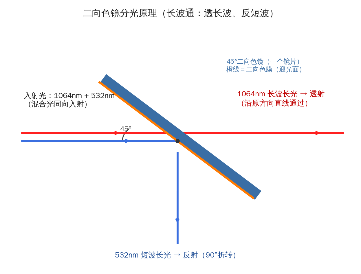
Figure 1. How a dichroic mirror splits light by wavelength: mixed light is incident at 45°, long-wavelength light transmits straight on and short-wavelength light is reflected through 90° (used in reverse, this combines beams) (drawn by Changsha Soar Laser)
2. Physical Principles: How Multilayer Interference ‘Sculpts’ One Transmitted and One Reflected Band
2.1 Bragg interference in multilayer dielectric coatings
High-index materials (Ta₂O₅, TiO₂, Nb₂O₅, HfO₂ and so on) and low-index material (SiO₂) are deposited alternately on a polished substrate, each layer usually designed with a quarter-wave optical thickness at the reference wavelength (a λ/4 stack). Fresnel reflection at a single interface is weak (a few per cent), but when reflections from dozens to hundreds of interfaces add in phase at a particular wavelength, total reflectance can exceed 99.9%; at another wavelength the interface reflections cancel out of phase and light is almost fully transmitted. This is the distributed Bragg reflector (DBR) principle; a dichroic mirror is essentially a Bragg stack variant optimised for reflection in one band and transmission in another.
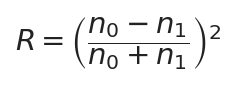
Fresnel reflectance at a single interface, where n0 and n1 are the refractive indices on either side

Bragg wavelength condition: reflection is coherently enhanced when the sum of layer phase thicknesses is an integer multiple of half a wavelength
Two engineering implications follow. First, the greater the index contrast between high and low layers, the fewer layers are needed for a given reflectance and the wider the reflection band — Ta₂O₅/TiO₂ (n≈2.1–2.4) with SiO₂ (n≈1.45–1.46) is common in the visible and near-infrared, HfO₂/Al₂O₃ is used in the ultraviolet, and fluorides or chalcogenides in the infrared. Second, commercial coatings make extensive use of non-λ/4 optimised designs — fine-tuning individual layer thicknesses around a λ/4 skeleton and adding matching layers to flatten passband ripple and sharpen the transition edge, which is why ‘identical-looking long-pass filters’ from different makers differ greatly in passband flatness.
2.2 Spectral Structure: Cut-On and Cut-Off Wavelength, Transition Band and Ripple
Taking a long-pass filter as an example, from short to long wavelength the sequence is: blocking band → transition edge → passband.
- Cut-on and cut-off wavelength (called cut-on for long-pass and cut-off for short-pass): most commonly defined as the wavelength at T=50%; steepness conventions vary — Edmund Optics defines slope from the 10% to 80% transmission points, while Semrock defines transition width as the guaranteed span from the ‘OD>6 point to the 50% transmission point’. The convention must be confirmed before purchasing, requesting measured curves annotated with AOI and polarisation.
- Transition width: around 20–40 nm for general-purpose types, down to the 5 nm scale for laser-grade hard coatings. A narrower transition means more layers and greater sensitivity to thickness monitoring, so cost rises non-linearly.
- Ripple: residual Fabry–Pérot-like reflection oscillations within the passband, arising from effective-index mismatch between the stack, substrate and incident medium, suppressed with matching layers; premium hard coatings keep it within about 2%.
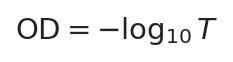
Definition of optical density (blocking depth): OD6 corresponds to T=10⁻⁶
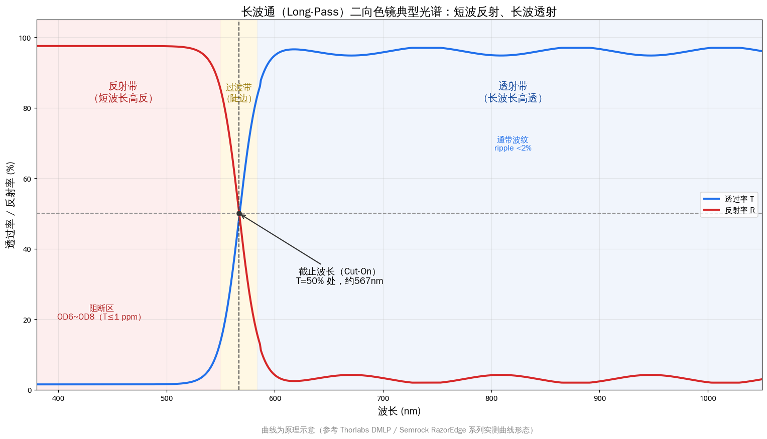
Figure 2. Typical T/R spectrum of a long-pass dichroic mirror: blocking band, transition band (steep edge) and passband, with cut-on defined at T=50% (drawn by Changsha Soar Laser)
2.3 Angle-of-Incidence Effects: Blue Shift (the Most Critical Issue)
At oblique incidence the refraction angle inside the layers increases and the wave-vector component normal to the coating decreases, reducing the effective phase thickness; to re-satisfy the interference condition the wavelength must be shortened — hence as the angle of incidence increases, the reflection spectrum shifts bodily towards shorter wavelengths (blue shift) (an explicit conclusion from RP Photonics). A quantitative estimate:
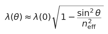
Estimate of the blue shift in cut-on wavelength at oblique incidence, where n_eff is the effective index of the coating (typically about 1.5–2.0)
For a typical coating with n_eff≈1.5–2.0, the cut-on edge shifts blue by about 6%–12% from 0° to 45° — roughly 70–130 nm at 1064 nm, enough to render a coating designed for 0° completely ineffective at 45°, which is the root cause of the classic ‘0° coating installed in a 45° path’ accident. Sensitivity near the design angle should follow manufacturer measurements: about 0.20%/degree for Semrock laser dichroics (35°–55°) and about 0.35%/degree for fluorescence types (40°–50°), equivalent to roughly 1–2 nm/degree at 532 nm and 2–4 nm/degree at 1064 nm. Rays within a converging beam have different AOIs, effectively ‘smearing’ the steep edge; high-NA systems must request performance curves over an angular range based on the convergence half-angle (some catalogues specify 0.5°).
2.4 Polarisation Effects: the Split Between s and p
At non-normal incidence, s polarisation (electric field perpendicular to the plane of incidence) and p polarisation (field parallel to it) have different optical admittances in the layers, so their reflection-band widths and edge positions separate. The typical behaviour at 45° is: the s-polarised reflection band is wider with higher reflectance, while the p-polarised band narrows with lower reflectance, with edges differing by several to a dozen or so nanometres. Measured examples: the Semrock LPD02-532RU is specified R>94% at 532 nm, with s R>98% and p R>90%; LASER COMPONENTS HR1064HT532/45° gives 1064 nm R>99.9% (s) / >99.5% (p) and 532 nm T>93% (s) / >97% (p). The polarisation state must therefore be stated when ordering; evaluate random polarisation by the average and leave margin for the worst case, or commission a low-polarisation-split coating (usually at the cost of steepness or extra layers).
2.5 Energy Conservation, Low Absorption and Thermal Lensing
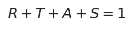
Energy conservation: reflectance + transmittance + absorption + scattering sums to 1
Metallic coatings can absorb several per cent, with all that heat retained in the coating; all-dielectric coatings absorb at the ppm level (premium IBS hard coatings down to a few ppm, evaporated films typically an order of magnitude higher), and thus withstand high power. However, the transmitted path’s energy must pass through the substrate, and slight substrate absorption plus residual coating absorption still accumulate at high average power, producing a thermal lens effect via the thermo-optic coefficient (dn/dT) and thermal expansion — the focused spot enlarges and the focal point drifts, the most common ‘soft failure’ of high-power dichroic mirrors, often misdiagnosed as a damaged laser or f-theta lens. Mitigations: low-absorption IBS coatings, thicker or low-expansion substrates, and improved mount heat sinking.
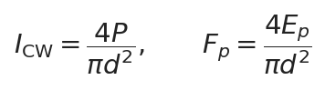
CW power density (W/cm²) and pulsed fluence (J/cm²), where P is power, Ep is single-pulse energy and d is spot diameter
2.6 Substrate Materials and Rear-Surface Treatment
| Substrate | Typical transmission range | Characteristics and typical applications |
|---|---|---|
| UV-grade fused silica (UVFS) | approx. 180 nm–2.5 μm | Very low thermal expansion, low bulk absorption, thermal-shock resistance and negligible autofluorescence; first choice for high-power UV-to-near-IR work, standard substrate at Thorlabs and Semrock |
| BK7 / H-K9L | approx. 350 nm–2.0 μm | Low cost and easy to machine; general low-power visible applications (use fused silica instead below 380 nm or at high power) |
| Calcium fluoride (CaF₂) | approx. 180 nm–8 μm | Good UV and mid-IR transmission, low dispersion; soft and hygroscopic |
| Sapphire | approx. 200 nm–5 μm | Extremely hard with good thermal conductivity; harsh environments and special wavelengths such as 2.94 μm (note birefringence) |
| Zinc selenide (ZnSe) | approx. 0.5–22 μm | Transmits both visible red light and 10.6 μm (n≈2.40, bulk absorption about 5×10⁻⁴/cm); the mainstream substrate for CO₂ combining, soft and toxic — never handle with bare hands |
| Silicon (Si) / germanium (Ge) | approx. 1.2–8 / 2–16 μm | Opaque to visible light with good thermal conductivity; mid- and far-IR mirrors and windows, unsuitable for red alignment beams |
The standard construction is a dichroic functional coating on one face and an anti-reflection (AR) coating on the other. Without a rear AR coating, roughly 4% residual reflection forms a ghost beam offset parallel to the main beam — producing double images and raising microscope background; a more refined approach gives the substrate a small wedge (typically 30 arcminutes to several degrees) so the residual reflection leaves the main path. Always check the manufacturer’s orientation marks during assembly: on Thorlabs circular optics the engraved arrow points to the AR face, while on 25 mm × 36 mm rectangular plates the engraved face is the dichroic coating; on Semrock rectangular plates the coated face carries the part number and faces the incoming light.
2.7 Cold and Hot Mirrors, and Coating Processes
Cold mirrors have high visible reflectance and high near-IR transmittance (long-pass behaviour), directing ‘cool light’ where it is needed while letting heat leak out behind; hot mirrors do the opposite, transmitting visible and reflecting infrared (short-pass behaviour), intercepting thermal radiation before detectors, film or heat-sensitive samples. Both are special cases of broadband dichroic mirrors, optimised for broadband average reflectance and thermal stability rather than steep edges, with transitions hundreds of nanometres wide; they cannot be used to separate two laser lines. Install with the coated face towards the source so infrared is reflected away before entering the substrate.
The deposition process directly determines absorption, scattering and environmental stability: electron-beam (E-Beam) and thermal evaporation produce porous layers prone to moisture uptake and drift; ion-assisted deposition (IAD) partially densifies them; ion-beam sputtering (IBS) and magnetron sputtering yield dense, near-bulk-density layers with low absorption and scattering, no humidity drift and cleanability like ordinary glass, making them the mainstream process for high-power lasers and premium fluorescence filters (the Thorlabs DMLP series, for example, combines IBS hard coatings with fused silica). It should be noted that ns-pulse damage thresholds are not necessarily highest with IBS — evaporated films optimised for particular materials and wavelengths can also reach very high thresholds; a high LIDT results from the combined optimisation of coating material, design and process, and selection should rely on the supplier’s measured reports under identical test conditions.
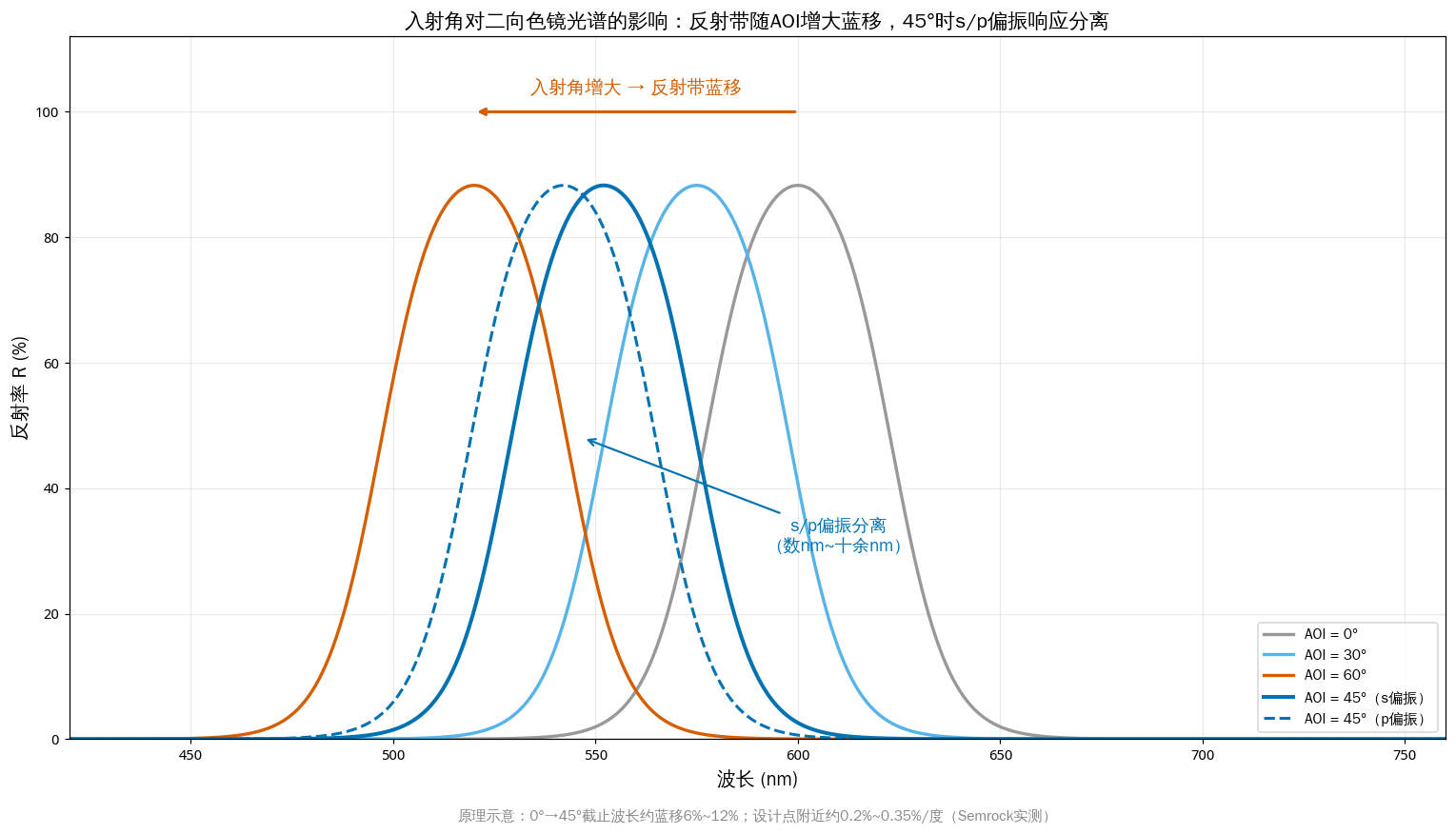
Figure 3. Effect of angle of incidence: the reflection band blue-shifts as AOI increases, and s/p polarisation responses separate at 45° (drawn by Changsha Soar Laser)
3. Structure and Classification
By coating spectral function:
- Long-pass (LP): reflects short wavelengths and transmits long ones. The most widely used type — ‘reflect 650 nm red, transmit 1064 nm main laser’ falls into this category.
- Short-pass (SP): transmits short wavelengths and reflects long ones, as in pump injection mirrors (transmit pump, reflect laser) and harmonic separators (reflect 1064 nm, transmit 532 nm).
- Bandpass: transmits only one narrow band and reflects outside it, equivalent to one LP edge plus one SP edge.
- Multiband / trichroic: several transmission bands plus several reflection bands; for RGB combining and multicolour fluorescence a single plate replaces two, but the coating is complex and lead times are long.
- Notch: an extremely narrow reflection band (reflecting only one or two laser lines) with high broadband transmission elsewhere, commonly used to reject the Rayleigh line in Raman spectroscopy.
By angle of incidence: 45° (most common, with the widest standard range), 0° normal incidence (filter wheels, coaxial paths, intracavity components), 22.5° and other custom angles. Coatings must be selected for the actual AOI: mount the same mirror at a different angle and its spectrum changes completely.
By shape and mounting: circular bare plates (Ø12.7, Ø25.4, Ø50.8 mm and other standard apertures), rectangular plates (25 × 36, 25.2 × 35.6 mm and other microscope-cube standard sizes), and mounted assemblies (plug-and-play, avoiding hand contact with the coating).
By application area: industrial high-power laser types (LIDT and heat dissipation), fluorescence microscopy types (steepness, OD, surface figure and low autofluorescence), projection RGB combining types (colour purity and angular tolerance), illumination hot and cold mirror types (broadband average reflectance and temperature resistance), and Raman spectroscopy types (notch depth and steepness).
Multiwavelength cascade configuration: a 1064 + 532 + 355 nm three-in-one processing head normally uses several long-pass dichroic mirrors in series: the first reflects 355 nm and transmits 532 and 1064 nm; the second reflects 532 nm and transmits 1064 nm. Each plate must be checked for ‘high R at the reflected wavelength plus high T at the others’ — 1064 nm passes through the most plates and suffers the greatest loss; wedge angles accumulate optical-axis deviation; and stray light must be caught by a beam dump.
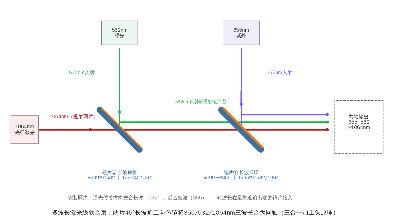
Figure 4. Two 45° long-pass dichroic mirrors in series combine 355/532/1064 nm step by step onto a common axis (principle of a three-in-one processing head) (drawn by Changsha Soar Laser)
Selection quick-reference table:
| Classification dimension | Option | Typical applications and key point in one line |
|---|---|---|
| Coating function | Long-pass (LP) | Reflect short-wavelength alignment light, transmit the long-wavelength main laser; first choice for red-beam combining |
| Coating function | Short-pass (SP) | Harmonic separation, pump injection; reflects long and transmits short |
| Coating function | Bandpass / multiband / notch | RGB combining, multicolour fluorescence, Raman; one plate replaces several but costs more |
| Angle of incidence | 45° / 0° / 22.5° | 45° has the widest standard range; do not use at a different angle |
| Substrate | UVFS / BK7 / ZnSe | Choose fused silica for high power and UV; ZnSe is mandatory for 10.6 μm CO₂ |
| Format | Circular / rectangular / mounted | Select to suit the mount or cube interface, noting clear aperture and coated-face orientation |
4. Key Technical Parameters and Their Selection Significance
4.1 Spectral parameters
| Parameter | Meaning and typical values | Selection significance |
|---|---|---|
| Cut-on / cut-off wavelength | Called cut-on for long-pass and cut-off for short-pass, mostly defined at T=50%; custom accuracy typically about ±0.5% to ±2% of wavelength | The most critical parameter; confirm the manufacturer’s convention (50% point / 10–80% / OD6 point) and rely on measured curves |
| Transmittance T | Passband T_avg typically >90–95%, laser/fluorescence grades >93–98% (e.g. Semrock T_avg>93%) | Determines main-path power utilisation; at high power every 1% of loss turns into heat |
| Reflectance R | Blocking-band R_avg typically >90–95%, high specification >99% (higher for s polarisation) | Determines the efficiency of the split-off path: red-beam brightness, pump efficiency and stray-light suppression |
| Transition steepness / transition width | General catalogue types about 20–40 nm (Thorlabs DMLP567: blocking band ends at 550 nm, transmission starts beyond 584 nm); laser-grade hard coatings down to the 5 nm scale (Semrock RazorEdge transition width 5.3 nm, steepness 2.7 nm) | Determines whether closely spaced spectral lines can be separated, and is a major price divider |
| Blocking depth OD | OD=−log₁₀T; OD6 = T≤10⁻⁶, OD8 = 10⁻⁸; OD6 or better is generally required for fluorescence/Raman | Excitation light is millions of times stronger than fluorescence; insufficient OD lets leakage swamp the signal; OD3–6 is usually adequate for laser combining |
| Angle of incidence (AOI) and tolerance | Standard 45°; drift near the design angle about 0.2–0.35%/degree (Semrock measurements), total blue shift 0°→45° about 6–12% | A wrong mounting angle causes blue-shift failure; allow angular adjustment in the mount and provide the convergence half-angle for converging light |
| Polarisation dependence s/p | At 45° the s/p edges and reflectances separate (example: at 532 nm, s R>98% versus p R>90%) | Accept linearly polarised light against the corresponding polarisation; leave margin for the worst polarisation with random polarisation |
| Passband ripple | Premium hard coatings can keep passband ripple within about 2% (typical) | Large ripple makes signals fluctuate with wavelength and fluorescence-channel brightness uneven |
| Group-delay dispersion (GDD) | A specification specific to femtosecond systems, in fs²; rises sharply near the transition edge | Affects pulse duration and shape; ultrafast lasers must separately confirm a low-dispersion coating |
4.2 Mechanical, geometric and reliability parameters
| Parameter | Meaning and typical values | Selection significance |
|---|---|---|
| Laser-induced damage threshold (LIDT) | Pulsed 10 ns: catalogue visible mirrors about 0.4–2 J/cm² at 532 nm (Thorlabs conditions 10 ns/10 Hz/Ø250 μm); high-power grades about 10–30 at 1064 nm, 5–10 at 532 nm, 5 at 355 nm (LASER COMPONENTS); CW about 1 MW/cm² (about 5 for high-reflectance coatings), strongly dependent on heat dissipation | The primary failure risk at high power; request measured reports stating wavelength/pulse width/spot size/repetition rate, and leave margin at one-half to one-third of the stated value |
| Surface figure / transmitted wavefront error (TWE) | Commonly λ/4 to λ/10 at 633 nm; Thorlabs DMLP specifies TWE≤λ/4 | Affects transmitted spot quality and focusing; choose a tighter grade for precision processing/imaging |
| Reflected wavefront error (RWE) | Semrock offers Standard and Laser grades, with Laser-grade RWE<6λ P-V at 632.8 nm | Critical to imaging quality in the reflected path, often overlooked; most microscope illumination spot distortion originates here |
| Surface quality (scratch-dig) | Industrial hard coatings commonly 40-20 (Thorlabs DMLP is 40-20); 20-10 for high power/UV; some microscope filters 60-40 | Scratches and pits are scattering sources and initiation sites for high-power damage |
| Parallelism / wedge angle | Parallelism commonly <3 arcminutes; wedged plates typically 30 arcminutes to several degrees | A wedge suppresses ghost return light but causes beam deviation, which accumulates across cascades; wedged plates have an installation direction |
| Substrate material and thickness | UVFS / BK7 / ZnSe and others; circular plates commonly 3 mm thick, microscope rectangular plates 1.0–2.0 mm | Material sets the wavelength band and power ceiling; thickness affects heat capacity, wavefront and the focal shift of a plane-parallel plate (changing thickness requires recalibration) |
| Clear aperture | Typically 80–90% of the outer diameter (e.g. CA≥Ø22.9 mm for a Ø1″ plate) | The spot must fall entirely within the CA (recommended spot diameter at least 1.2–1.5 times smaller); the edge clamping zone is unusable |
| Environmental reliability | Hard coatings resist moisture and UV and can be cleaned like ordinary glass (Thorlabs); commonly cited standards include ISO 9211 (optical coatings), ISO 9022 (environmental testing), ISO 21254 (LIDT) and MIL-PRF-13830B (surface quality) | Soft coatings absorb moisture and drift spectrally; confirm wipe and damp-heat resistance on site; record orientation marks in the assembly SOP |
Note: the above are typical industry values or published sample values; they vary greatly with manufacturer, coating design, pulse width/spot size/repetition rate. Final selection should rely on the supplier’s measured reports under identical test conditions.
5. Characteristics: Advantages and Limitations
Advantages:
- Precise wavelength selection: transition edges can be as narrow as single-digit nanometres, distinguishing close wavelengths such as 532 and 538 nm, with extremely high channel isolation thanks to OD6+ blocking.
- High efficiency: both paths are used at close to full strength, far better than 50:50 splitting (which loses at least half in each path).
- High-power capability: all-dielectric coatings absorb down to the ppm level and, with a fused-silica substrate, withstand very high average and peak powers.
- High blocking depth: OD6 to OD8 rejection is beyond the reach of absorbing filters.
- Highly customisable: cut-on and cut-off wavelength, bandwidth, steepness, AOI, polarisation, LIDT and dispersion can all be designed to order.
- Long life, no fading: inorganic dielectric coatings contain no organic dyes and do not yellow with prolonged illumination (IBS hard-coating makers often offer a 10-year warranty).
- Light thermal-management burden: the rejected band is reflected away rather than absorbed, so waste heat does not build up inside the component.
Limitations:
- Strong angle dependence: any change in AOI causes a blue shift; converging beams also ‘smooth out’ the steep edge because their rays have differing AOIs.
- Polarisation dependence: s and p performance separate at 45°, so randomly polarised light must be evaluated against the worst polarisation.
- Sensitivity to contamination: fingerprints, oil mist and metal spatter form absorption centres that heat locally and then burn outward at high power — the most common failure mode.
- Higher cost than absorbing filters: dozens to hundreds of layers and IBS/IAD processing are expensive, so laser-grade steep-edge products cost far more than coloured glass.
- Substrate absorption and thermal lensing: slight substrate absorption still causes wavefront distortion and focal drift at high average power.
- Coating stress and ghost reflections: internal stress in hard coatings can bow thin substrates; poor rear AR coating or no wedge inevitably leaves a ghost beam.
- Reflected light must be managed: the reflected energy does not disappear and must be caught by a beam dump or baffle (in this respect absorbing filters are ‘cleaner’).
6. Typical Applications and Selection Advice
Typical applications:
- Red alignment-beam combining (most common in marking/welding/cutting): the main laser (1064/532/355 nm) is transmitted while 635/650 nm red light is reflected into the coaxial path, using a 45° long-pass coating with the cut-on between the red and main wavelengths — a red beam combiner is essentially a dichroic mirror.
- Multiwavelength laser combining and splitting: 1064/532 harmonic separation (short-pass: reflect 1064, transmit 532), 355/532/1064 three-wavelength cascades, and diode-pump coupling (transmit pump, reflect laser).
- Fluorescence microscopy excitation/emission splitting: placed at 45° in a filter cube, excitation light is reflected into the objective, longer-wavelength fluorescence transmits to the camera/PMT, and residual excitation is reflected away from the detection channel. Exciter, dichroic mirror and emitter form a co-designed three-piece set; cross-brand mixing is not recommended.
- RGB combining in projection and stage lighting: red, green and blue channels each use a dichroic mirror (or a trichroic mirror / X-Cube prism) to synthesise white light, demanding broadband performance, temperature resistance and large apertures.
- Optical communications and pump coupling: combining and separating 915/976 nm pump light with 1064/1550 nm signals, emphasising low insertion loss and high isolation.
- Raman spectroscopy: a steep-edge dichroic delivers the laser to the sample and collects the Raman-shifted light, paired with notch/edge filters to suppress the Rayleigh line (Semrock RazorEdge transition widths can be below 1% of the laser wavelength).
- Illumination hot and cold mirrors: cold mirrors are used in fibre illumination, surgical lamps and projector reflectors to leak infrared away; hot mirrors protect heat-sensitive film, samples or detectors.
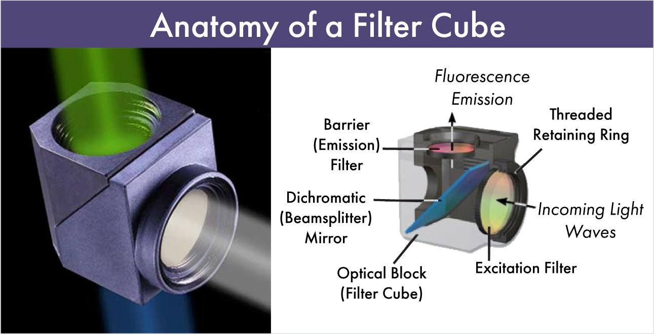
Figure 5. An epi-fluorescence filter cube: exciter selects the band → dichroic mirror reflects it into the objective → fluorescence transmits → emitter selects the band reaching the detector (image source: Omega Optical)
Six-step selection method:
- Define transmitted/reflected wavelengths and power: list the central wavelength, spectral width and power/energy of each path, distinguishing CW from pulsed operation (pulse width, repetition rate) — CW is limited by heat build-up, pulsed by field-induced breakdown.
- Define AOI and polarisation state: confirm the actual incidence angle (usually 45°) and polarisation direction; leave margin for the worst polarisation with random polarisation; provide the convergence half-angle for converging beams.
- Allow transition-band margin: keep the operating wavelength at least one transition width from the edge — 30–50 nm for general-purpose types (20–40 nm transition) and 10–15 nm for laser steep-edge coatings (about 5 nm); also allow for angle tolerance and laser wavelength temperature drift (diode chips about 0.2–0.3 nm/°C).
- Select substrate and LIDT by power and pulse width: use fused silica plus low-absorption IBS coating for high average power; check the 10 ns threshold for nanosecond pulses; check GDD as well for femtosecond work; lock to ZnSe for CO₂. Set the operating limit at one-half to one-third of the stated LIDT.
- Define surface figure, surface quality and wavefront: imaging/focusing paths require attention to TWE and RWE (choose Laser-grade low RWE for microscopy); high power requires attention to 20-10 surface quality and defect density; cascades require attention to wedge angle.
- Define mounting size and allow alignment tolerance: clear aperture at least 1.2–1.5 times the beam diameter (1/e²); allow ±2° to ±5° angular adjustment; fix the coated-face orientation mark on the assembly drawing.
Incoming inspection (a commonly missed step): re-measure the T/R curve with a spectrophotometer at the actual AOI and polarisation state — do not accept a 45° component against 0° data; sample wavefront with an interferometer; check scratches, pits and orientation marks by dark-field microscopy; request LIDT reports with test conditions.
Selection examples:
- Example 1 | red alignment on a 1064 nm marker: 45° long-pass with cut-on chosen at 700–950 nm (keep 650 nm deep in the blocking band and 1064 nm deep in the passband — never set it near 650 nm); 1064 nm T>95% (commercial combiner specifications can reach T>99%), 650 nm R>85–95%; fused-silica substrate (BK7 is also acceptable for low-power visible use); λ/4 surface figure, 40-20 surface quality; coated face towards the incoming light; beam dump for stray light.
- Example 2 | 532 nm fluorescence microscopy: edge wavelength about 537 nm, reflecting 532 nm (R>94%, s>98% / p>90%) and transmitting fluorescence beyond 538.9 nm (T_avg>93%), with transition width ≤5.3 nm and emitter OD>6 at the laser wavelength; low-autofluorescence fused-silica substrate 1.0–2.0 mm thick to fit the cube; choose Laser grade with low RWE; replace the three-piece set as a group.
- Example 3 | coaxial red alignment for 10.6 μm CO₂: fused silica and BK7 absorb strongly at 10.6 μm, so a ZnSe substrate is mandatory (transmits 0.5–22 μm); coating reflects 630–670 nm and transmits 10.6 μm; account for bulk absorption (about 5×10⁻⁴/cm), thermal lensing and heat dissipation; ZnSe is soft and toxic — never handle with bare hands and never acid-clean. GaAs is opaque to visible light and cannot provide red alignment.
- Example 4 | 355 nm UV processing head: the substrate must be fused silica (BK7 transmits poorly in the UV and darkens under fluorescence); low-absorption IBS hard coating; damage threshold typically about 5 J/cm² at 355 nm / 10 ns; contaminants photochemically darken under UV, so enclose and purge the optical path cleanly — once the coating hazes over, the damage is irreversible.
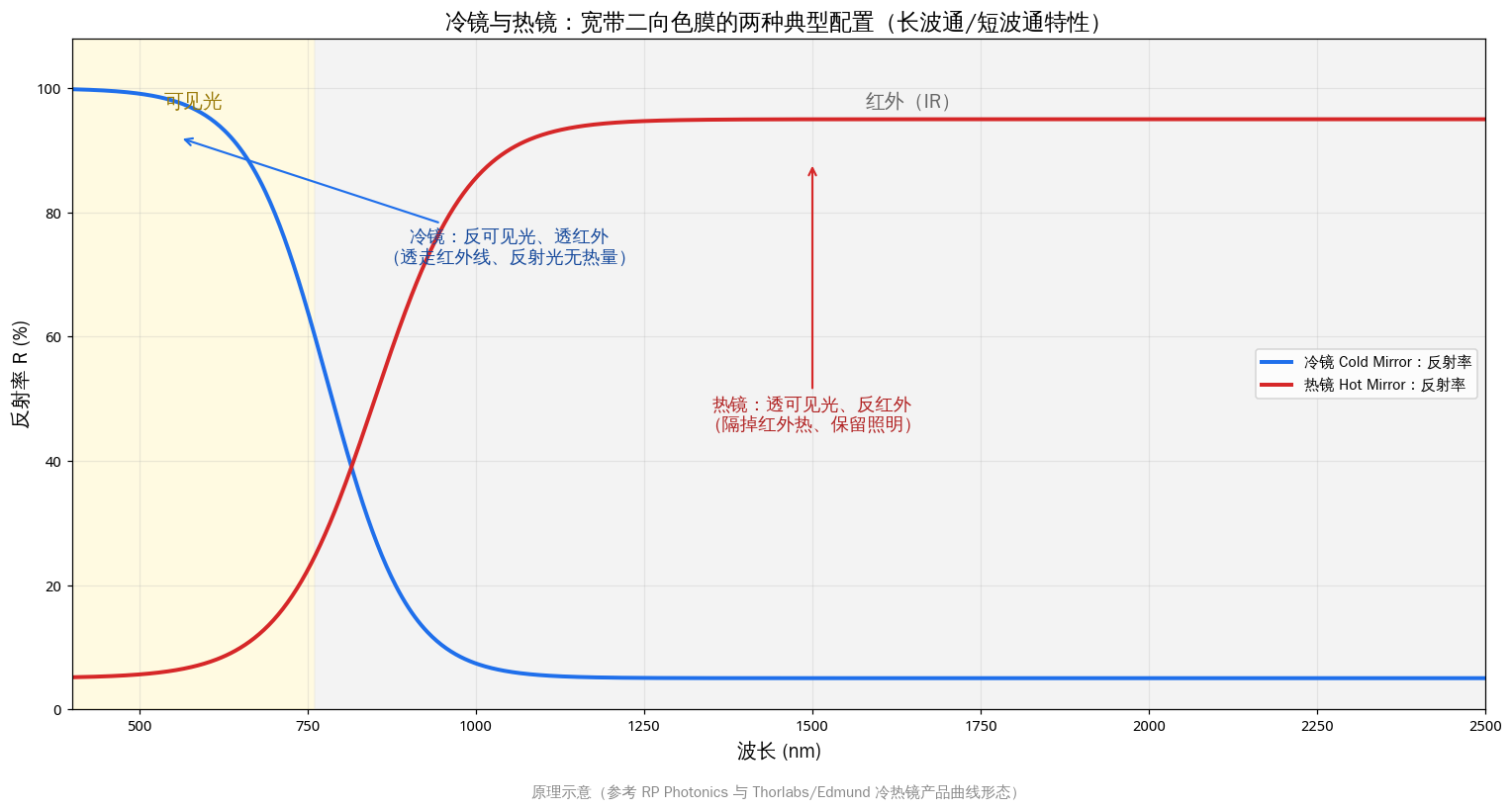
Figure 6. Cold mirrors reflect visible and transmit infrared; hot mirrors transmit visible and reflect infrared: two typical broadband dichroic configurations (drawn by Changsha Soar Laser)
7. Common Misconceptions and Pitfalls
| Misconception | Correct understanding / consequence |
|---|---|
| 1. Treating a dichroic mirror as a 50:50 neutral beamsplitter | A dichroic mirror gives all-reflect or all-transmit by wavelength and has no fixed splitting ratio; use a neutral beamsplitter or PBS for power-ratio splitting |
| 2. Installing a 0° coating in a 45° path | Increasing AOI blue-shifts the reflection spectrum, typically 6–12% from 0° to 45° (about 70–130 nm at 1064 nm): what should be transmitted is reflected, and the apparently ‘intact’ mirror fails completely |
| 3. Ignoring s/p polarisation | At 45° p reflectance is markedly lower than s (example at 532 nm: s>98% versus p>90%); leave margin for the worst polarisation with random polarisation |
| 4. Setting the cut-on right at the operating wavelength (red plate cut-on near 650 nm) | The operating wavelength lands on the transition slope, so small changes in temperature, angle or batch cause large fluctuations; red-combining cut-on must be longer than 650 nm |
| 5. Substituting coloured glass or dyed filters for high-power coated plates | Absorbing types turn all rejected energy into heat, cracking or fading and drifting above the watt level; the rejected band should be ‘reflected away’ rather than ‘absorbed’ |
| 6. Installing the coated face backwards | Functional coating and rear AR are reversed, introducing ghost reflections and extra loss; install by the engraved line/arrow (arrow points to the AR face on circular plates, the engraved face is the coating on rectangular ones) and write this into the SOP |
| 7. Applying high power to a contaminated coating | Fingerprints, oil mist and spatter are absorption centres that burn pits and spread well below the stated LIDT; blow off loose dust first, then wipe gently in one direction with solvent — dry wiping is strictly prohibited |
| 8. Watching only reflectance and ignoring wavefront and ripple | TWE, RWE and passband ripple distort the spot and shift focus; in microscope imaging RWE is often more critical than the R value |
| 9. Confusing cold and hot mirrors or installing them backwards | Cold mirrors reflect visible and transmit infrared (delivering cool light); hot mirrors reflect infrared and transmit visible (blocking heat); both are broadband coatings and cannot replace steep-edge laser dichroics |
| 10. Purchasing ‘beam combiner’ and ‘dichroic mirror’ as two separate products | ‘Beam combiner’ is an application name and ‘dichroic mirror’ a coating-property name for the same component; enquire in coating terms: ‘HT/HR wavelengths + AOI + polarisation + substrate + LIDT’ |
| 11. Looking only at catalogue centre wavelength, ignoring pulse width, spot size and test conditions | LIDT varies dramatically with wavelength, pulse width, spot size and repetition rate; the CW threshold is in W/cm² and depends strongly on heat dissipation, so pulsed J/cm² values cannot be applied |
| 12. Ignoring cumulative loss and wedge deviation in cascades | Residual reflection/transmission and wedge accumulate, deviating the optical axis and creating stray light; 1064 nm passes the most plates and suffers the most loss, so the whole chain must be evaluated |
| 13. Selecting for converging paths using collimated-light specifications | Rays in a converging beam have differing AOIs, effectively ‘smoothing’ the steep edge; the convergence half-angle must be provided |
| 14. Making do with telecom WDM or bandpass filters for laser combining | Telecom components are designed to the ITU wavelength grid and telecom AOIs; wavelength, angle and LIDT all mismatch laser conditions and they fail once power exceeds limits |
| 15. Assuming ‘the transmitted path has no loss and generates no heat’ | The transmitted path passes through the substrate, with rear reflection, substrate absorption and thermal lensing; high-power focal drift is often misdiagnosed as a laser or f-theta lens fault |
| 16. Failing to absorb the reflected light | Reflected energy does not disappear; a beam dump or baffle must be placed correctly, or repeated intracavity reflection becomes a safety hazard |
8. Historical Development and Notes
The technical history of the dichroic mirror is the evolution chain of thin-film optics: metallic reflective coatings → single- and multilayer dielectric AR coatings → computer-aided coating design → precision ion-beam-sputtered coatings. Early mirrors relied on silver, aluminium and gold films, broadband but with several per cent absorption, neither high-power-capable nor wavelength-selective. In 1935 A. Smakula of Carl Zeiss Jena patented the single-layer dielectric AR coating; by the mid-20th century λ/4 Bragg stack theory had matured, making ‘splitting by wavelength’ a designable, repeatable engineering capability; after lasers appeared in the 1960s, computer coating optimisation (the Needle method, Monte-Carlo and others) freed hundred-layer designs from manual trial and error. The first edition of H. Angus Macleod’s Thin-Film Optical Filters was published by Adam Hilger in 1969, systematising coating design into a standard discipline (now in its 5th edition, CRC Press, 2018). Dense and non-porous with low absorption and scattering and no long-term spectral drift, IBS coatings became the technological basis for high-end filters from Semrock, Chroma and Alluxa and for high-power laser coatings.
Cold and hot mirrors were born in the era of film projection and stage lighting: infrared from projector lamps would bake the film, leading to hot mirrors reflecting IR back towards the lamp and cold-mirror reflectors sending visible light out while leaking IR away — the first broadband dichroics mass-produced at scale. The fluorescence filter three-piece set (exciter / dichroic / emitter) matured after the 1990s alongside the explosion of fluorescence microscopy, flow cytometry and life-science assays; Semrock, Chroma and others pushed ‘steep transition + deep blocking + low autofluorescence + low RWE’ to engineering limits, making ‘change channel = change cube’ standard practice.
Modern trends: first, low-dispersion dichroics for ultrashort pulses, with GDD especially large near the transition edge, so ultrafast processing and multiphoton imaging now treat low GDD as a standalone specification; second, multiband and ultrabroadband coatings, giving several reflection/transmission bands in one plate; third, higher LIDT and lower absorption, with low-absorption hard coatings plus ultrasmooth substrates becoming standard for kilowatt-class processing; and fourth, integration, with dichroic coatings deposited directly on prisms, fibre end faces and detector windows.
Terminology boundaries in one sentence: a dielectric plate that reflects one band and transmits another by wavelength is a dichroic mirror; a beam combiner is its application name in combining scenarios; neutral beamsplitters divide by power ratio, PBS by polarisation state, coloured glass by absorption and dispersive prisms by refraction — the splitting principle differs, so they cannot substitute for one another.
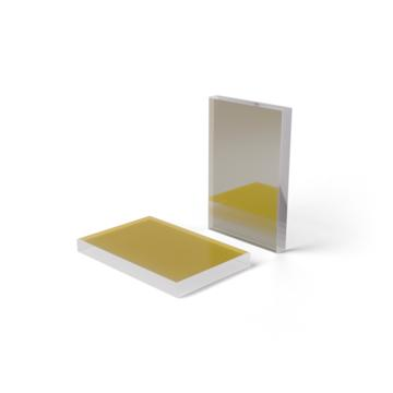
Figure 7. An industrial dichroic mirror in practice: the coated face shows the characteristic coloured interference reflection of a dielectric coating (image source: LASER COMPONENTS)
9. References
- RP Photonics Encyclopedia, Dichroic Mirrors (definition, long-pass/short-pass, angle and polarisation dependence)
- RP Photonics Encyclopedia, Dielectric Mirrors (Bragg reflection, index contrast versus layer count/bandwidth, blue-shift mechanism with incidence angle)
- RP Photonics Encyclopedia, Hot Mirrors / Cold Mirrors (definitions and the principle of facing the coating towards the source)
- RP Photonics Encyclopedia, Interference Coatings and Beam Splitters
- Thorlabs, Longpass / Shortpass Dichroic Mirrors & Beamsplitters (45° coatings, UV fused-silica substrates, IBS hard coatings, orientation marks and LIDT test conditions)
- Semrock (IDEX Health & Science), LPD02-532RU RazorEdge Dichroic Beamsplitter and Raman Optical Filter Catalog (transition width/steepness definitions, s/p reflectance, angular sensitivity, RWE grades)
- LASER COMPONENTS, Dichroic Mirror Coatings data sheet (HR/HT nomenclature, substrate selection rules, typical T/R and 10 ns and CW damage thresholds)
- Edmund Optics, Optical Filters application note (10%–80% slope definition, uses of OD grades, mechanistic differences between absorbing and dichroic types)
- H. A. Macleod, Thin-Film Optical Filters, 5th ed., CRC Press, 2018 (first edition 1969, Adam Hilger) — a classic thin-film optics textbook
- T. Erdogan, V. Mizrahi, ‘Thin-Film Filters for Raman Spectroscopy,’ Spectroscopy, December 2004 (thin-film filters and steep-edge dichroics for Raman)
- Alluxa, Hard-Coated Optical Filters technical literature; Chroma Technology, fluorescence filter set technical documentation
- CVD ZnSe material handbook (public sources such as MT Berlin / Ideal Photonics): bulk absorption coefficient about 5×10⁻⁴ cm⁻¹ at 10.6 μm, transmission range about 0.5–22 μm
- ISO 21254 (laser damage threshold testing), ISO 9211 (optical coatings), ISO 10110 (optical drawing conventions), ISO 9022 (environmental testing), MIL-PRF-13830B (surface quality)
📚 Further reading
- Beam combiner encyclopedia: red alignment combining, wavelength/polarisation/angle combining and 45° mirror selection
- F-theta lens encyclopedia: selection of the core marking and focusing component
- Laser beam expander encyclopedia: principles, classification, selection and use
- Laser collimator encyclopedia: collimation principles, lens-group design and industrial selection
- Laser protection window encyclopedia: selection and materials for cutting, welding, f-theta and galvanometer protection windows
- Polarisation rotators (Faraday rotators, half-wave plates and liquid-crystal types: principles and selection)
🔧 Related Products and Services
Changsha Soar Laser supplies a full range of laser-processing optics and selection support: red alignment beam combiners / dichroic mirrors (in stock on fused-silica substrates at 1064, 532 and 355 nm, with 45° long-pass coatings transmitting the main laser and reflecting 650 nm red light, in common Ø20, Ø25, Ø25.4 and Ø30 mm sizes); ZnSe-substrate dichroic combiners for 10.6 μm CO₂ lasers (transmitting 10.6 μm and reflecting the red alignment beam, with complete mounts and red-diode assemblies available). We also supply protection windows, focusing lenses, collimators, f-theta lenses and beam expanders to suit mainstream cutting, welding and marking heads from RayTools, Jiaqiang, Wanshengxing, Hongshan and Han’s Laser. Dichroic mirrors for special wavelengths, incidence angles, polarisation states and high LIDT requirements can be supplied to order against measured spectral curves.
Selection hotline (same number on WeChat): 15927220467. Tell us the main laser wavelength, alignment-beam wavelength and machine or head model, and we will check the cut-on wavelength, substrate, size, coated-face orientation and damage threshold for you.
Leave a Reply