


Introduction: Why Your Lens Always “Reflects”
When you raise your phone to photograph a sunset, or look at the world through your eyeglasses, have you ever noticed one detail: glass surfaces reflect part of the light?
Do not underestimate this phenomenon. In the world of optics, when light travels from air (refractive index ≈ 1.0) into glass (refractive index ≈ 1.5), roughly 4% of the light energy is reflected back at the interface. What does that mean? For every 100 rays entering a lens, 4 are “bounced” away for nothing.
For an ordinary window pane, 4% reflection hardly matters. But for precision optical instruments—astronomical telescopes, microscopes, high-end camera lenses—what does that 4% mean? It causes:
- Reduced image contrast and less vivid colors
- Glare and ghosting that degrade image quality
- Transmission loss, especially noticeable in low-light conditions
More importantly, when light passes through multiple lens elements, reflection accumulates. An ordinary camera lens contains 5-8 elements, and the cumulative reflection loss can exceed 30%!
The essence of the problem: We are not pursuing a “higher” transmission rate; we are fighting against the laws of physics—trying to make the interface “forget” that it is an interface, so light passes through without obstruction.
That, precisely, is the mission of the anti-reflection coating (AR Coating).
Thin-Film Interference: Making Light “Destroy Itself”
1. Thin-film interference from high school physics
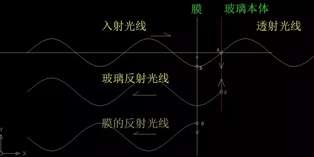
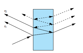
Do you still remember the “thin-film interference” experiment from your high school physics textbook? When sunlight shines on a soap bubble, you see iridescent stripes—the result of light reflected from the top and bottom surfaces of the film overlapping and interfering with each other.
The design of anti-reflection coatings is inspired by exactly this. The core idea is “using light to control light”: make the two reflected beams interfere destructively so that they cancel each other out.
2. How a single-layer AR coating works
Imagine depositing a transparent thin film on the glass surface (typically magnesium fluoride, MgF2, with a refractive index of about 1.38). What happens when light is incident on it?
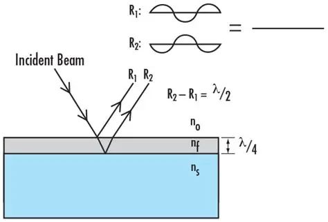
The light is split into two beams:
- Beam one (R1): reflected at the air-film interface
- Beam two (R2): transmitted through the film, reflected at the film-glass interface, then transmitted through the film once again
On their own, these two beams would produce the annoying reflections we see. But clever engineers discovered that by carefully designing the film thickness, the two beams can be made to “fight” each other—when they meet at the interface, one is positive while the other is negative, canceling each other out.
3. Quarter-wavelength design: the core formula of AR coatings
The film thickness is not chosen at random. Optical designers found that the cancellation effect is best when the optical thickness of the film equals one quarter of the incident light’s wavelength.
Key formula: d = λ/(4n)
where d is the film thickness, λ is the incident wavelength, and n is the refractive index of the film
Why a quarter wavelength? Here is one way to understand it: R2 travels the extra “down and back” round trip compared with R1, which is exactly half a wavelength (2×λ/4n = λ/2n); combined with the phase inversion, this produces a perfect 180° phase difference—that is, perfect destructive interference.
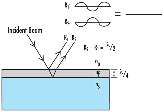
When the two reflected beams cancel perfectly, the interface “forgets” it is an interface and nearly all of the incident light passes through—this is the basic principle of the single-layer AR coating.
Impedance Matching: From “Head-On Collision” to “Soft Landing”
1. Why introduce the concept of impedance matching?
Thin-film interference explains AR coatings from the wave optics perspective, but if we look at it from the electromagnetic wave viewpoint, we find a more fundamental concept: impedance matching.
In electromagnetics, light, as an electromagnetic wave, also has an “impedance”. As light propagates through a medium, it encounters an equivalent impedance related to the refractive index of that medium. The greater the impedance difference between two media, the stronger the reflection at the interface.
It is like sound traveling from air into water: the sudden impedance change causes most of the sound to be reflected back instead of entering the water.
2. The quarter-wavelength impedance transformer
How can the impedance “transition smoothly”? Engineers borrowed a classic solution from RF and microwave technology: the quarter-wavelength impedance transformer.
Its principle is simple: insert an “intermediate layer” between the two impedances, and this layer’s impedance equals the geometric mean of the two.
Impedance matching formula:
Z1 (air) = 1.0
Z2 (glass) = 1.5
Zm (matching layer) = √(Z1 × Z2) = √(1.0 × 1.5) ≈ 1.225
When the optical thickness of the matching layer is one quarter of a wavelength, it acts as a gradual transition—the light passes from air into glass “without noticing” any obvious “step”, and the reflection naturally disappears.
3. Impedance matching vs thin-film interference: two sides of the same coin
Interestingly, the cancellation condition of thin-film interference and the optimum condition of impedance matching are essentially the same mathematical expression. They merely describe the same physical phenomenon from different angles:
| Perspective | Core concept | Design goal |
|---|---|---|
| Wave optics | Thin-film interference | Make the two reflected beams opposite in phase and cancel each other |
| Electromagnetics | Impedance matching | Make the interface impedance transition smoothly and eliminate reflection |
Single-Layer vs Multilayer Coatings: Not a Choice but a Positioning Question
1. Single-layer coating (V-Coat): specialized but limited
The classic single-layer MgF2 AR coating only achieves good anti-reflection at a single wavelength (or a very narrow band). This is because the quarter-wavelength design is optimized for a specific wavelength—once you move away from that wavelength, the cancellation condition is no longer satisfied.
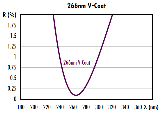
The reflectance curve shows that a single-layer coating can approach zero reflectance at the design wavelength (266nm), but the reflectance rises sharply at other wavelengths. This is why the lenses of older cameras show colored reflections at certain angles (usually blue-purple or amber)—that is precisely the result of non-optimized wavelengths being reflected.
2. Multilayer coatings: the all-rounder for broadband and wide angles
Modern optical designs use multilayer structures to overcome the limitations of single-layer coatings. By stacking 2-5 or even more thin films with different refractive indices, it is possible to achieve:
- Broadband anti-reflection: low reflectance across the entire visible band (400-700nm)
- Wide-angle applicability: good performance over a large range of incidence angles
- Omnidirectional broadband: excellent performance from 0° to 60° incidence
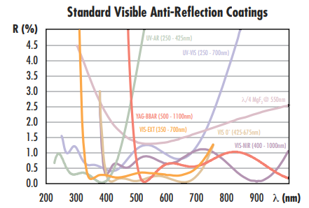
The comparison clearly shows that the multilayer coating (blue curve) maintains reflectance below 0.5% across the entire visible band, whereas the single-layer coating (red curve) rises sharply at the band edges. That is the secret behind the “reflection-free” look of modern lenses.
3. Infrared AR coatings: challenges on another battlefield
In infrared optics, AR coating design faces different challenges: longer incident wavelengths, a wider variety of substrate materials, and harsher thermal environments.
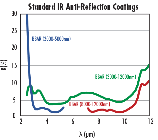
Infrared AR coatings need to achieve low reflectance in specific infrared bands (commonly 800-1100nm, 1300-1600nm, etc.) while maintaining performance stability in high-temperature environments.
Three Mainstream Processes: The Trade-off Between Cost and Performance
1. Wet coating: the economical entry-level choice
| Attribute | Description |
|---|---|
| Process principle | A solution (sol) containing the coating material is evenly applied to the substrate surface, then heated and cured to form a thin film |
| Main advantages | Low equipment investment, simple process, large-area production possible |
| Main disadvantages | Poor film density, low wear resistance, mediocre optical performance |
| Typical applications | Photovoltaic coated glass, ordinary display cover glass, eyeglass lenses |
2. Dry magnetron sputtering: the mainstream performance-first choice
| Attribute | Description |
|---|---|
| Process principle | Inside a vacuum chamber, high-energy ions bombard a target so that atoms are sputtered out and deposit on the substrate surface |
| Main advantages | Dense, uniform films with strong adhesion; excellent optical performance; precise control of multilayer structures |
| Main disadvantages | Large equipment investment, complex process control, relatively high production cost |
| Typical applications | High-end camera lenses, smartphone camera modules, automotive optical systems, AR/VR display panels |
3. Moth-eye nanostructures: the ultimate biomimetic application
| Attribute | Description |
|---|---|
| Process principle | Mimicking the nano-cone structures on moth eyes, sub-wavelength periodic structures are formed on the substrate surface to create a gradient refractive index |
| Main advantages | Truly omnidirectional broadband anti-reflection; works at extreme incidence angles; no secondary reflection from thin-film interfaces |
| Main disadvantages | Extremely complex process, very high cost, currently limited to high-end specialty applications |
| Typical applications | Military night-vision devices, space telescopes, high-power laser systems, medical endoscopes |
Real-World Applications: AR Coatings Are Everywhere
1. Photography optics
From smartphone cameras to professional SLR lenses, AR coatings are everywhere. Modern smartphone camera modules typically use 5-7 layers of nanoscale multilayer coatings to keep reflectance below 0.3% across the full 400-700nm band, ensuring sharp images under all lighting conditions.
2. Consumer electronics displays
Tablets, laptops, smartwatches—almost every device with a screen relies on AR coatings. They dramatically improve screen visibility in sunlight while reducing power consumption (because more light enters the display instead of being reflected).
3. Automotive optics
Automotive cameras, lidar covers, HUD head-up displays—vehicle intelligence has made AR coatings a safety-critical component. Automotive AR coatings must withstand temperatures from -40°C to 85°C, placing extremely high demands on durability.
4. Photovoltaics
An AR coating on solar panel surfaces can raise photocurrent efficiency by 2-4%. For a large photovoltaic plant, that means several million additional kilowatt-hours of electricity every year.
5. Astronomical optics
Although the primary mirrors of large telescopes do not need AR coatings, lens assemblies (such as corrector lenses) must use high-performance AR coatings. After all, what a telescope captures is faint starlight from billions of light-years away, and any reflection loss is a huge waste.
Conclusion: A Thin Film with Great Wisdom
From the thin-film interference experiment in high school physics textbooks to modern nanoscale multilayer designs, AR coating technology has evolved over more than a century. It may look like nothing more than a thin transparent film, yet it condenses the combined wisdom of wave optics, electromagnetics, materials science, and precision manufacturing.
The next time you raise your phone to take a photo, or admire the scenery through your glasses, think about this: how many photons complete the marvelous journey of “self-annihilation” at these interfaces before the world appears before our eyes?
The beauty of optics lives in every invisible thin film.
This article is based on professional optical resources such as Edmund Optics and covers the complete technical chain from fundamental principles to industrial applications. Corrections are welcome if anything is missing.
Leave a Reply