


Optical Resonators Explained: Stable Cavities, Unstable Cavities and Mode Selection
An optical resonator is the skeleton of a laser. It does not merely provide optical feedback — it decides the modes, the stability and the beam quality. But what makes a cavity stable? How should the g-parameter diagram be read? Is an unstable resonator really “unstable”? And how do you select the fundamental mode TEM₀₀? This article works through the stability criterion, the g-parameter diagram and the methods of mode selection, as a design guide for laser engineers and researchers who need to understand cavity design in depth.
Contents
- 1. Why Bother Understanding Cavity Design in Depth?
- 2. The Stability Criterion: g Parameters and the Stability Diagram
- 3. Comparing the Common Stable Cavity Types
- 4. Unstable Resonators: The Choice for High Power
- 5. Mode Selection: How Do You Get TEM₀₀?
- 6. Key Parameters: Reading the Engineering Figures of a Resonator
- 7. Common Misconceptions
1. Why Bother Understanding Cavity Design in Depth?
If you have already read Optical Resonators: The Basics and know how a resonator is put together and what its resonance condition is, the next questions are these: how should the two mirrors be chosen? What radius of curvature? What cavity length? How do you guarantee the cavity is stable? And how do you get a high-quality fundamental-mode beam? These are precisely the core questions of laser resonator engineering.
Stable or unstable, plano-concave or confocal, how large an aperture? These choices set the output power, the beam quality, the misalignment tolerance and the range of applications directly. Drawing on authoritative sources including the RP Photonics · Optical Resonators, this article covers the stability criterion, a comparison of typical cavity types and the methods of mode selection.
If you want the principle and parameters of the Fabry–Pérot interferometer or etalon as a filtering element, read What Is a Fabry–Pérot Resonator?.
2. The Stability Criterion: g Parameters and the Stability Diagram
The most important way to classify an optical resonator is by stability. Stable means that a paraxial ray, after many round trips, never departs far from the optical axis — it stays trapped inside the cavity. Unstable means the ray walks further off axis at every pass and eventually escapes past the edge of a mirror.
2.1 Defining the g parameters
For a resonator formed by two spherical mirrors, each mirror is given a g parameter:
gi = 1 – L / Ri
where Ri is the radius of curvature of mirror i and L is the cavity length. Note the sign convention for the radius: R is positive when the concave side faces into the cavity, negative when the convex side does, and a flat mirror has R → ∞ so that g = 1.
The stability condition of the resonator is:
0 ≤ g₁ · g₂ ≤ 1
When g₁·g₂ lies strictly between 0 and 1 the resonator is stable; when it equals 0 or 1 it is marginal (edge-stable); when it is less than 0 or greater than 1 it is unstable.
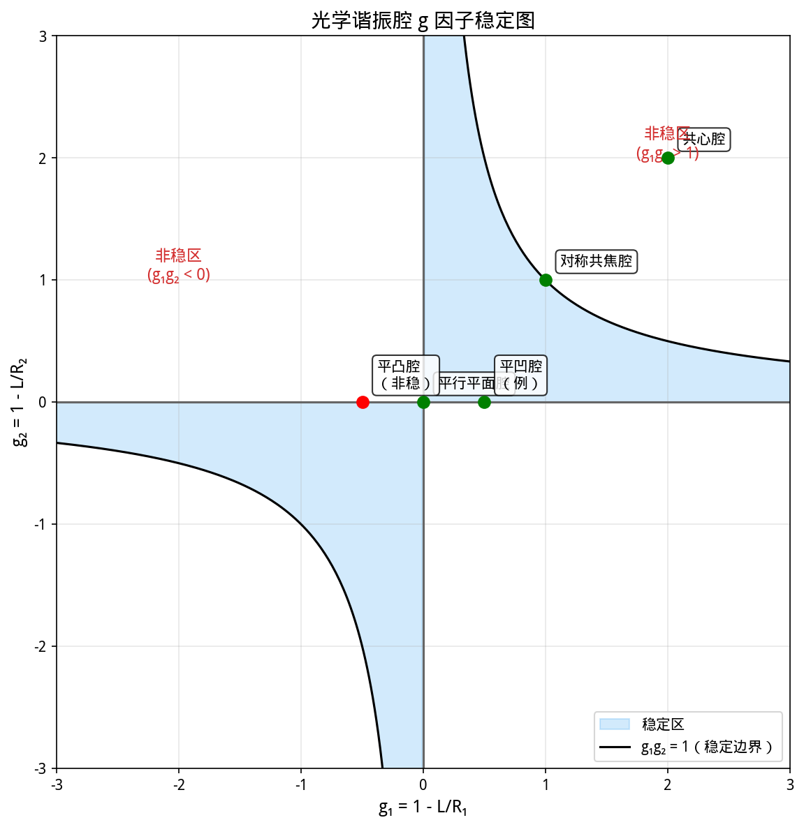
Figure 1: the g-parameter stability diagram of an optical resonator. The blue area is the stable region (0 < g₁g₂ < 1), split into the first quadrant (two concave mirrors, or one flat and one concave) and the third quadrant (two convex mirrors). Points on the hyperbolas satisfy g₁g₂ = 1 and points on the axes satisfy g₁g₂ = 0; both are marginally stable.
2.2 What the g-parameter diagram means
The g-parameter diagram is the most direct tool for understanding stability. There are four key regions:
- First-quadrant stable region (g₁ > 0, g₂ > 0, g₁g₂ < 1): the most used stable region, containing the various concave-mirror cavities. The symmetric confocal cavity (R₁ = R₂ = L, g₁ = g₂ = 0) sits at the origin; the plane-parallel cavity (R → ∞, g₁ = g₂ = 1) sits at the top-right corner.
- Third-quadrant stable region (g₁ < 0, g₂ < 0, g₁g₂ < 1): two convex mirrors facing each other, rarely used in practice.
- Second and fourth quadrants (g₁g₂ < 0): unstable regions, easily reached by a concave-plus-convex combination.
- The region g₁g₂ > 1: unstable, reached with two concave mirrors whose radii are too small or whose separation is too large.
💡 Engineering note: in practice stay away from the edges of the stable region, that is, from g₁g₂ close to 0 or 1. At an edge-stable point the beam size either diverges (towards infinity) or collapses (towards zero), and the misalignment sensitivity is very high — a slight tilt of a mirror throws the beam a long way, making alignment and stable operation difficult. A value of g₁g₂ between 0.3 and 0.7 is usually a safe choice.
3. Comparing the Common Stable Cavity Types
Stable cavities are what the great majority of lasers from low to medium-high power use. These are the common types and how they behave:
3.1 Symmetric confocal cavity
Two concave mirrors, each with a radius of curvature equal to the cavity length (R₁ = R₂ = L), with both focal points coinciding at the centre. Then g₁ = g₂ = 0, the origin of the g diagram — right on the boundary of the stable region. The confocal cavity is the most stable configuration, because moving away from the origin in any direction keeps you inside the stable region.
Its characteristics: the largest Gouy phase shift (π/2 per pass), the widest transverse-mode frequency spacing and a high degree of mode degeneracy; the mode volume is small, which suits low-gain lasers that need high beam quality.
3.2 Plano-concave cavity
One flat mirror plus one concave mirror, the simplest structure. Its g parameters are g₁ = 1 (flat mirror) and g₂ = 1 − L/R₂.
When R₂ > L, g₁·g₂ = 1 − L/R₂ lies between 0 and 1 and the cavity is stable. When R₂ = L, g₂ = 0 and g₁·g₂ = 0, giving a semi-confocal cavity (marginally stable). The plano-concave cavity is the first choice for many small solid-state lasers and external-cavity diode lasers, because it is simple to adjust and cheap.
3.3 Bi-concave cavity (symmetric and asymmetric)
With concave mirrors at both ends, the parameters are the most flexible. Adjusting the two radii and the length gives different mode volumes, waist positions and misalignment sensitivities within the stable region. A symmetric bi-concave cavity (R₁ = R₂) has its waist at the centre and a larger mode volume, which is a common design for solid-state lasers.
3.4 Concentric cavity
Two concave mirrors whose centres of curvature coincide at one point inside the cavity, so that R₁ + R₂ = L if both face inwards. Then g₁·g₂ = 1, on the boundary of the stable region. The mode volume is large but alignment is difficult — a small error turns it into an unstable cavity with a sharp rise in loss. Early ruby lasers used plane-parallel and concentric cavities; in practice today they are rarely seen.
3.5 Ring cavity
Three or more mirrors forming a closed loop. A ring cavity has no standing wave and no spatial hole burning, which makes single-frequency operation easier. It can be stable or near-stable, and its stability is analysed with the ABCD matrix for one round trip. A common problem is astigmatism from oblique incidence; bow-tie geometries keep the angles small to minimise it RP Photonics · Ring Resonators.
| Cavity type | g₁·g₂ | Mode volume | Misalignment sensitivity | Typical use |
|---|---|---|---|---|
| Symmetric confocal | 0 (marginal) | Small | Low | Low gain, high beam quality |
| Plano-concave | 0 to 1 (adjustable) | Medium | Medium | Small lasers, external-cavity diodes |
| Symmetric bi-concave | 0 to 1 (adjustable) | Medium to large | Medium | Solid-state lasers |
| Concentric | 1 (marginal) | Large | Very high | Early lasers, now seldom used |
| Ring | Adjustable within the stable region | Medium | Medium | Single-frequency and mode-locked lasers |
4. Unstable Resonators: The Choice for High Power
The name puts many people off — “unstable” sounds like a bad cavity. In fact an unstable resonator is not a bad cavity at all; it is an important configuration for high-power, high-energy lasers.
4.1 How an unstable resonator works
In an unstable resonator a paraxial ray keeps walking outwards on each round trip until it escapes past the mirror edge. That is precisely how it couples light out: the output coupling mechanism is the leakage past the rim of the mirror, producing a hollow annular beam. Because no transmissive window has to be drilled in the mirror, fully reflecting optics can be used, which raises the damage threshold substantially.
4.2 Positive- and negative-branch unstable resonators
There are two families:
- Positive-branch unstable resonator: the focus lies inside the cavity and the output has a real focus that downstream optics can collect directly. Astigmatism is comparatively large.
- Negative-branch unstable resonator: the focus lies outside the cavity, astigmatism is smaller, but the output has a virtual focus and needs additional collimating optics.
4.3 Magnification of an unstable resonator
A key parameter is the transverse magnification M — the factor by which the transverse size grows in one round trip. The larger the magnification, the higher the output coupling, since more light escapes past the edge. The geometric output coupling is 1 − 1/M².
4.4 Advantages and drawbacks
Advantages: a large mode volume that can fill a large gain medium; a small output divergence approaching the diffraction limit; and fully reflecting mirrors, hence a high damage threshold.
Drawbacks: the mode structure is complex and cannot be described by simple Gaussian modes; the output is annular with a dark centre and usually needs a telescope to reshape; and the intracavity loss is high, so a high-gain medium is needed to reach threshold.
Unstable resonators therefore suit high-power, high-gain lasers particularly well: military lasers, giant neodymium-glass lasers and high-power copper-vapour lasers among them RP Photonics · Unstable Resonators.
5. Mode Selection: How Do You Get TEM₀₀?
A stable cavity naturally supports several transverse modes at once (TEM₀₀, TEM₀₁, TEM₁₀, TEM₁₁ and so on). Many applications need a clean fundamental-mode beam, because the fundamental has the best beam quality and the smallest focus. So how do you select it?
5.1 Transverse selection: the aperture method
The simplest and most common method is to insert a small aperture. The principle is intuitive: higher-order transverse modes are larger than the fundamental, so an aperture sized between the fundamental spot and the first-order spot blocks the higher orders and passes the fundamental.
In practice a few points matter:
- Aperture position: at the beam waist it works best, because there the fundamental spot is smallest and the size difference from the higher orders is greatest.
- Aperture size: about 1.5 times the fundamental spot radius is usual — enough to suppress the higher orders without loading the fundamental with excessive loss.
- The cost: an aperture adds intracavity loss and reduces output power and efficiency. The higher the gain of the medium, the easier aperture selection becomes.
5.2 Transverse selection: cavity design
Choosing the cavity parameters appropriately can also give fundamental-mode operation. The idea is to make the diffraction loss of the higher-order modes far greater than that of the fundamental:
- Near-confocal operation: close to confocal the fundamental spot is small and the higher orders are large, so aperture selection works well.
- Reducing the Fresnel number: the Fresnel number N = a²/(Lλ), with a the mirror radius, the smaller it is the greater the diffraction loss, and the diffraction loss of the higher orders grows much faster than the fundamental’s. Too small a Fresnel number, however, also lowers the fundamental’s output efficiency.
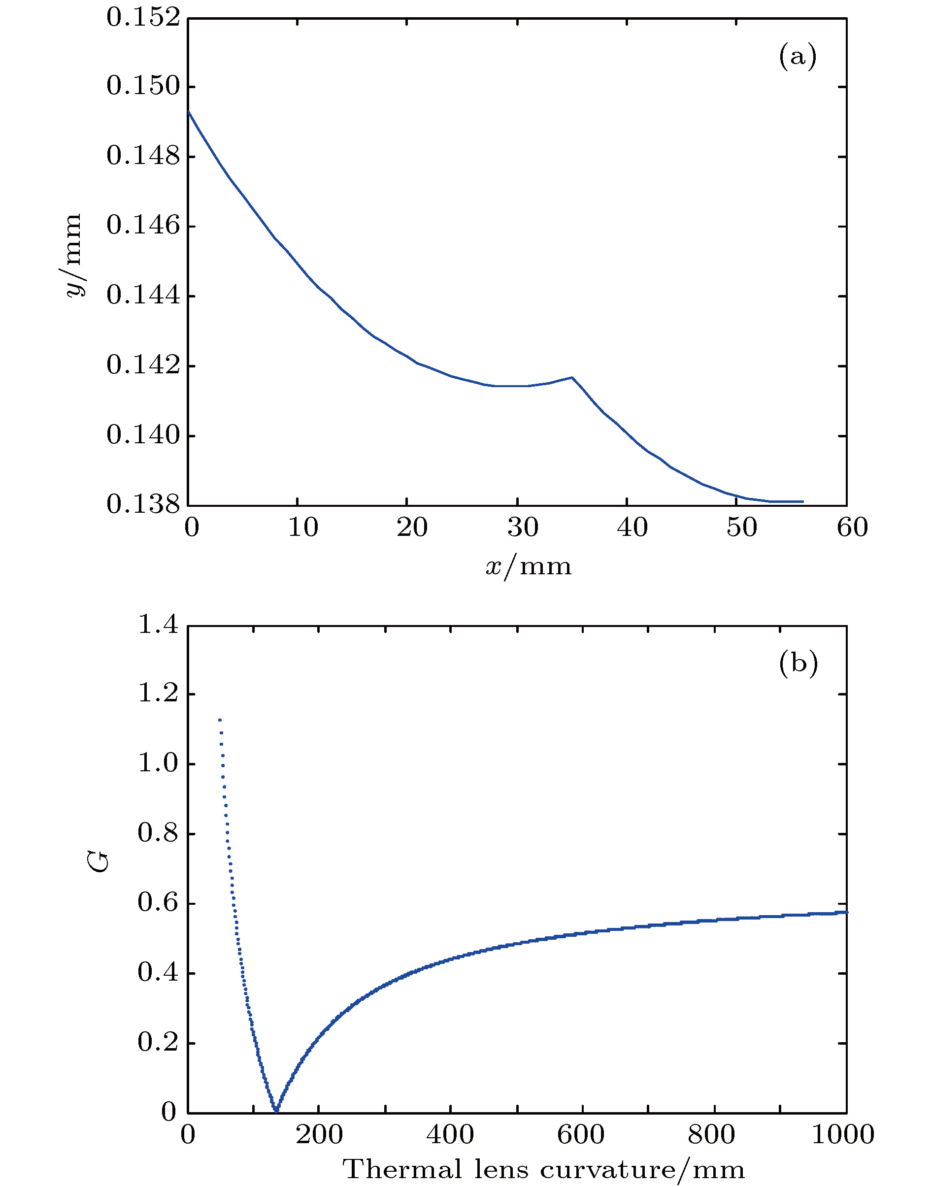
- Dynamic stable cavity: exploit the thermal lens so that the cavity sits at a favourable point in the stable region at the operating power, giving fundamental-mode output automatically.
5.3 Longitudinal selection: how do you get a single longitudinal mode?
Longitudinal modes matter as much as transverse ones. A laser with a 10 cm cavity has a free spectral range of about 1.5 GHz, while the gain bandwidth may be several THz (about 120 GHz for Nd:YAG), so dozens or hundreds of longitudinal modes can oscillate. To get single-longitudinal-mode (single-frequency) output the usual methods are:
- Short cavity: shorten the cavity to widen the FSR so that only one longitudinal mode falls inside the gain bandwidth. But a very short cavity limits output power.
- Intracavity etalon (F–P etalon): insert a thin Fabry–Pérot etalon whose narrower transmission peaks select a single longitudinal mode. Its FSR must span the whole gain bandwidth and its finesse must be high enough. The principle is covered in What Is a Fabry–Pérot Resonator?.
- Compound (multiple) cavity: cascade several resonators with different FSRs; only frequencies satisfying all the resonance conditions at once can oscillate, which is equivalent to a large increase in finesse.
- Ring cavity with an isolator: a ring cavity has no spatial hole burning, and with an optical isolator it gives stable single-frequency operation.
💡 Engineering note: real single-frequency lasers usually combine several methods — a ring cavity with an intracavity etalon and a birefringent filter, for instance — to select one longitudinal mode reliably across a wide gain bandwidth and keep it stable. The choice involves trading off linewidth requirement, output power, stability requirement, cost and complexity.
6. Key Parameters: Reading the Engineering Figures of a Resonator
With the stability criterion and mode selection covered, these are the parameters a cavity design has to master:
| Parameter | Meaning | Why it matters in selection |
|---|---|---|
| Free spectral range (FSR) | The frequency spacing between adjacent longitudinal modes, set by the cavity length and the refractive index of the medium | It sets the range and difficulty of single-longitudinal-mode selection; a longer cavity has a smaller FSR and is harder to make single-frequency |
| Finesse | The ratio of the FSR to the half-width of the resonance peak, a measure of frequency resolution | It measures frequency selectivity: the higher the finesse, the narrower the linewidth. It is set mainly by the cavity loss |
| Quality factor (Q) | The ratio of the resonance frequency to the linewidth, reflecting stored energy and selectivity | Q = ν/δν; the higher the Q, the longer the photon lifetime and the narrower the linewidth |
| Stability (g₁g₂) | The product of the g parameters, telling whether a ray stays confined over many round trips | The basis for judging where a cavity sits; too close to an edge makes it misalignment-sensitive |
| Mode volume | The space the fundamental mode occupies inside the cavity | It decides gain extraction efficiency; too small limits output power, too large allows multiple transverse modes |
| Misalignment sensitivity | How much a mirror tilt moves the beam | Critical in practice; a cavity that is too sensitive is hard to align and hard to keep stable |
| Diffraction loss | The loss from light escaping because the mirrors are finite | The diffraction loss of higher modes far exceeds the fundamental’s, which is the physical basis of transverse-mode selection |
| Total loss | Output coupling, absorption, scattering and diffraction together | It sets threshold power and slope efficiency, and is the central target of cavity optimisation |
7. Common Misconceptions
Opinions about cavity design are often plausible rather than correct. The following are widely repeated but inaccurate, and each needs sorting out:
Misconception 1: A concave-mirror resonator is always stable
Wrong. Stability depends not only on the mirror curvatures but on the cavity length; only the g parameters settle it. Two concave mirrors can give g₁·g₂ > 1 — and hence an unstable cavity — if the separation exceeds the sum of the radii of curvature, as happens with small radii and a long cavity.
Misconception 2: An unstable resonator is unstable and therefore fragile
“Unstable” refers to geometrical optics: paraxial rays drift further off axis on every pass. An unstable resonator is in fact a preferred configuration for high-power lasers, with a distinctive output-coupling mechanism and a large mode volume; designed properly it performs very well.
Misconception 3: A stable cavity must give TEM₀₀
A stable cavity supports Gaussian modes; it does not automatically deliver the fundamental. With enough gain several higher-order transverse modes oscillate at once and the beam quality drops. Getting a clean fundamental mode needs additional selection — an aperture, or optimisation of the cavity design.
Misconception 4: The closer to confocal, the better the cavity
The confocal cavity is the most stable, that is, the least sensitive to misalignment, but it has the smallest mode volume, which is poor for power extraction. Practical designs often sit in the middle of the stable region, balancing mode volume, alignment sensitivity and thermal stability.
Misconception 5: The higher the reflectivity, the better
High-reflectivity mirrors raise the finesse and the Q, but they also lower the output power, since there is too little output coupling, and they increase alignment difficulty and temperature sensitivity. The optimum reflectivity depends on the application: pulsed lasers usually take a lower reflectivity output coupler, continuous single-frequency lasers a higher one.
Misconception 6: A resonator has only two mirrors
A simple linear cavity does, but real laser resonators often contain several mirrors (folded or ring cavities) plus lenses, etalons and apertures. Folding reduces the size of the laser, compensates astigmatism and optimises the mode volume.
Leave a Reply