


Introduction: Polarisation-maintaining fibre (PM fibre) is a specially designed single-mode fibre that introduces strong directional birefringence in the core region, creating a large difference in propagation constant between the two orthogonal polarisation modes and thus preserving the linear polarisation state of the input light during transmission. A typical PM fibre has a beat length on the order of 1–5 mm (corresponding to birefringence B ≈ 10⁻⁴–10⁻³) and a polarisation extinction ratio (PER) of 20–40 dB, with slightly higher attenuation than standard single-mode fibre (about 0.5–2.5 dB/km at 1550 nm, due to stress-rod scattering). It is an irreplaceable core component in fibre-optic gyroscopes (FOG), interferometric sensors, PM fibre lasers and coherent optical communication systems.
1. Definition and Basic Concepts
1.1 What is polarisation-maintaining fibre?
Polarisation-maintaining fibre is a special single-mode fibre with strong built-in birefringence. Unlike standard single-mode fibre, it does not try to eliminate birefringence, but actively introduces directional birefringence far larger than environmental disturbances, so the two orthogonal polarisation modes cannot couple effectively and the polarisation state is transmitted stably.
RP Photonics defines PM fibre as: ‘specialty optical fibers with strong built-in birefringence, preserving the properly oriented linear polarization of an input beam’ [1].
1.2 Differences between PM fibre, standard single-mode fibre and single-polarisation fibre
| Characteristic | Standard single-mode fibre (SMF) | Polarisation-maintaining fibre (PM fibre) | Single-polarisation fibre (SP fibre) |
|---|---|---|---|
| Birefringence magnitude | ~10⁻⁷ (random, uncontrolled) | ~10⁻⁴–10⁻³ (directional, controlled) | ~10⁻⁴–10⁻³ + high loss difference |
| Number of transmitted polarisation modes | 2 (degenerate) | 2 (non-degenerate, decoupled) | 1 (the other polarisation is cut off) |
| Polarisation-holding mechanism | None (output polarisation drifts randomly) | Strong birefringence suppresses mode coupling | One polarisation mode is in the cut-off region |
| Alignment requirement | No polarisation alignment needed | Input must be aligned to the principal axis | Only one polarisation transmitted, no alignment needed |
| Typical loss @1550 nm | ≤ 0.2 dB/km | 0.8–2.5 dB/km | Higher than PM fibre |
| Cost | Lowest | Medium (5–20 times an SMF) | High |
Key distinction: PM fibre transmits two polarisation modes but suppresses coupling (‘carries two, does not mix’); single-polarisation fibre permits only one polarisation mode (‘carries one’). The two cannot be interchanged [1][2].
2. Physical Principles
2.1 Birefringence mechanism
The core physical mechanism of PM fibre is high birefringence — establishing a significant difference in refractive index along two orthogonal directions within the fibre cross-section.
Birefringence is defined as the difference between the slow-axis and fast-axis refractive indices:
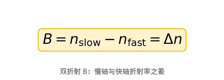
Two main approaches to introducing birefringence [1][3]:
(1) Stress-induced birefringence: stress-applying parts (SAPs), typically boron-doped silica with a different thermal-expansion coefficient, are embedded in the cladding on either side of the core. During drawing and cooling, the differential shrinkage between the SAPs and surrounding silica creates directional mechanical stress on the core, producing refractive-index anisotropy through the photoelastic effect. This is how PANDA and Bow-tie fibres work and is the most commercially mature approach.
(2) Form birefringence: birefringence from geometric asymmetry of the core (e.g. an elliptical core). No stress elements are needed, but the birefringence is usually lower than stress-induced types, used mainly in early research and low-cost sensors.
2.2 Coherent mode-coupling theory
PM fibre can maintain polarisation essentially by breaking the phase-matching condition between the two orthogonal polarisation modes.
When linearly polarised light enters along one principal axis, ideally only one polarisation mode is excited. In a real fibre, however, bending, twisting, temperature gradients and other disturbances create weak random coupling that transfers energy from the dominant mode to the orthogonal one.
According to coherent mode-coupling theory [1][4], the efficiency of this energy transfer depends on whether the spatial spectrum of the disturbance matches the propagation-constant difference of the two modes. When birefringence is strong enough, the difference Δβ is large:

Figure 1: Propagation-constant difference equation (drawn by Soar Laser)
At this point, the spatial frequencies of common environmental disturbances are far below Δβ and cannot provide effective phase matching, so mode coupling is strongly suppressed. Quantitatively, the polarisation beat length should be far smaller than the typical spatial scale of environmental birefringence changes [1].
2.3 Beat Length
Beat length is the core parameter measuring birefringence strength — the propagation distance over which the phase difference between the two orthogonal polarisation modes accumulates to 2π:

Figure 2: Beat-length equation (drawn by Soar Laser)
Taking 1550 nm as an example: if B = 3×10⁻⁴, then L_B = 1550 nm / 3×10⁻⁴ ≈ 5.2 mm. A shorter beat length means stronger birefringence and better PM performance.
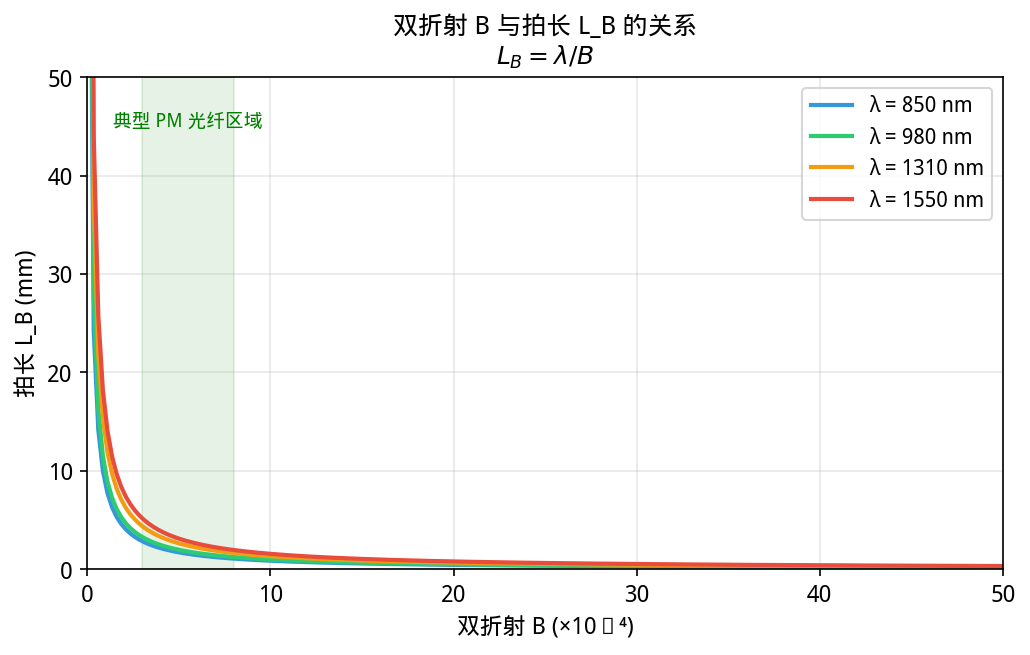
Figure 3: Inverse relationship of birefringence and beat length at different wavelengths (drawn by Soar Laser)
2.4 Fast axis and slow axis
A PM fibre has two orthogonal principal axes [1][5]:
– Slow axis: the direction of higher refractive index, where the wave’s phase velocity is lower
– Fast axis: the direction of lower refractive index, where phase velocity is higher
When linearly polarised light is launched precisely along the slow axis (or fast axis), only one polarisation mode is excited, there is no inter-mode interference, and the polarisation state remains unchanged along the fibre.
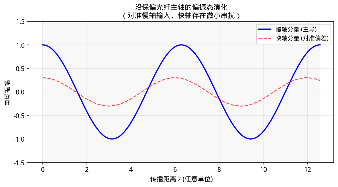
Figure 4: Polarisation evolution along a PM fibre — aligned principal-axis launch leaves only tiny crosstalk on the fast axis (drawn by Soar Laser)
3. Structure and Technical Classification
3.1 Main structural types
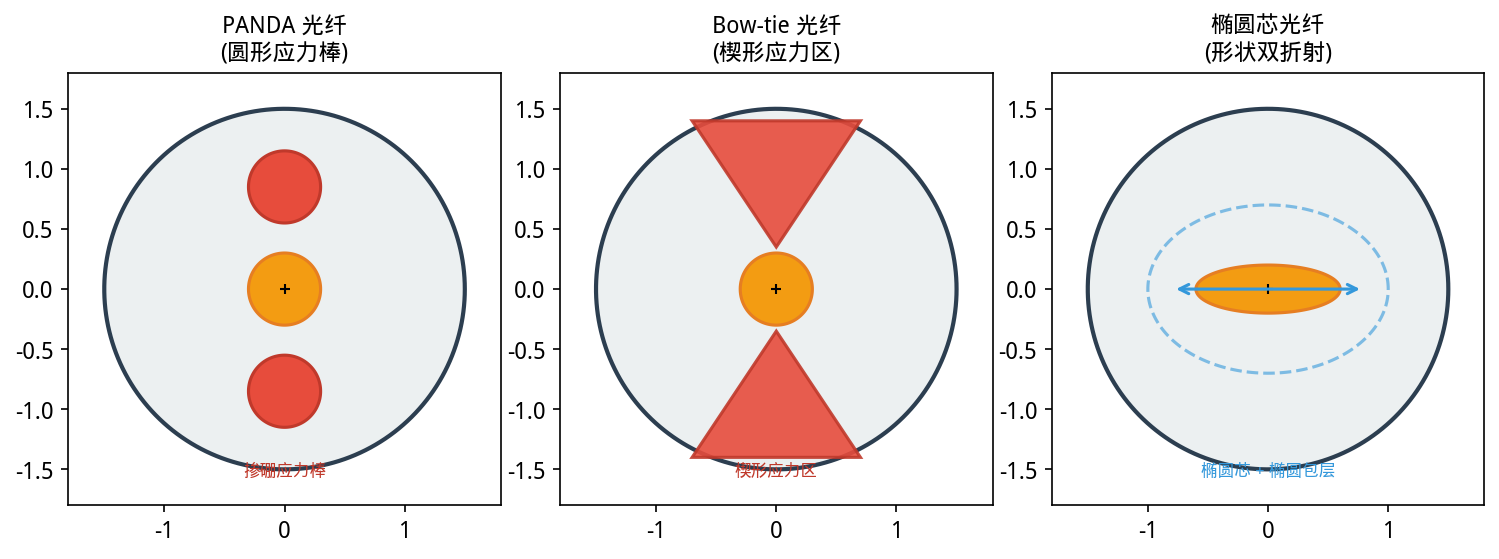
Figure 5: Cross-sections of three main PM fibre structures — PANDA (circular stress rods), Bow-tie (wedge-shaped stress regions), elliptical core (form birefringence) (drawn by Soar Laser)
(1) PANDA fibre (Polarisation-maintaining AND Absorption-reducing)
Invented in the early 1980s by teams including Y. Sasaki and K. Okamoto at NTT’s Ibaraki Electrical Communication Laboratories [6], later commercialised by Corning, Fujikura, Sumitomo and others. Two circular boron-doped stress-applying parts (SAPs), typically 30–40% of the cladding diameter, are embedded symmetrically on either side of the core. After drawing and cooling, the thermal-expansion difference between the borosilicate SAPs and pure silica creates directional stress, forming high birefringence.
Advantages: mature manufacturing, good splicing compatibility and strong batch consistency — the most mainstream commercial PM fibre type.
(2) Bow-tie fibre
The stress regions are wedge-shaped (fan-shaped), with tips close to the core — nearer than in PANDA — giving higher peak stress and greater birefringence, and typically a shorter beat length than PANDA [5][7].
Advantages: higher PER (35–45 dB), suited to high-end sensing such as navigation-grade FOGs.
Disadvantages: more difficult splice alignment and fewer suppliers.
(3) Elliptical-core fibre
Works by form birefringence, making the core elliptical. No stress elements are needed and manufacture is relatively simple, but the birefringence is usually lower than stress-induced types [1][8].
(4) Photonic-crystal PM fibre
Uses an asymmetric air-hole arrangement to produce ultra-high birefringence, with beat length down to the sub-millimetre scale. The index difference can reach 10⁻² or higher, far beyond the 10⁻⁴ order of all-glass PM fibres [1][9].
3.2 Structure comparison table
| Parameter | PANDA | Bow-tie | Elliptical core | Photonic crystal |
|---|---|---|---|---|
| Beat length L_B @1550 nm | 2–5 mm | 1.5–4 mm | 4–8 mm | 0.5–3 mm |
| Polarisation extinction ratio PER | 25–40 dB | 30–45 dB | 18–28 dB | 25–42 dB |
| Attenuation @1550 nm | 0.8–2.0 dB/km | 1.0–2.5 dB/km | 1.5–3.0 dB/km | 1–5 dB/km |
| Splice compatibility | Excellent (standard SMF tools) | Good (high alignment demand) | Medium (needs special tools) | Medium–poor |
| Temperature stability | High | Very high | Medium | High |
| Main applications | FOG, DAS, coherent systems | Navigation-grade FOG, interferometers | Research, low-cost sensors | High-power lasers, research |
| Relative cost | Medium | Medium–high | Low–medium | High |
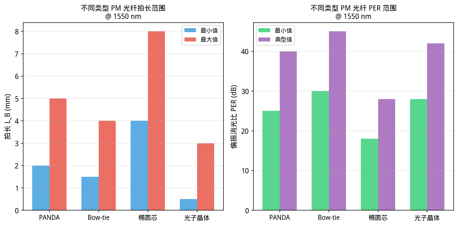
Figure 6: Comparison of beat-length and PER ranges for different PM fibre types (drawn by Soar Laser)
4. Key Parameters and Typical Values
| Parameter | Symbol | Unit | Typical range | Description |
|---|---|---|---|---|
| Beat length | L_B | mm | 1–5 (HiBi PM) | Shorter is better; navigation-grade FOG requires ≤3 mm @1550 nm |
| Birefringence | B (Δn) | Dimensionless | 1×10⁻⁴ – 5×10⁻³ | PCF can reach ~10⁻² |
| Polarisation extinction ratio | PER | dB | 20–40 | Device-level up to 22–30 dB (measured after connector end-face alignment) |
| Polarisation crosstalk | h / CT | dB/km or dB/m | ≤ −30 dB/km (typical) | Crosstalk accumulates with length; shorter fibre sections give higher PER |
| Attenuation | α | dB/km | 0.5–2.5 @1550nm | Higher than standard SMF (~0.2 dB/km), due to stress-rod scattering |
| Mode-field diameter | MFD | μm | 3.3–10.5 (depends on wavelength) | Must match other fibres in the system to reduce splice loss |
| Cut-off wavelength | λ_c | nm | 400–1450 (depends on model) | Must be below the operating wavelength to ensure single-mode operation |
| Numerical aperture | NA | Dimensionless | 0.12–0.20 | Usually nominal 0.12 |
| Cladding diameter | d_clad | μm | 60/80/125 | 125 μm standard; 80 μm and 60 μm for compact devices |
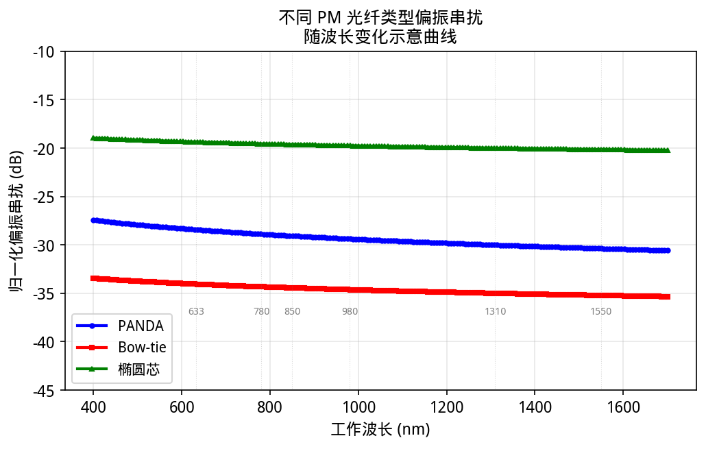
Figure 7: Typical crosstalk variation with wavelength/length (drawn by Soar Laser)
Polarisation extinction ratio (PER) definition
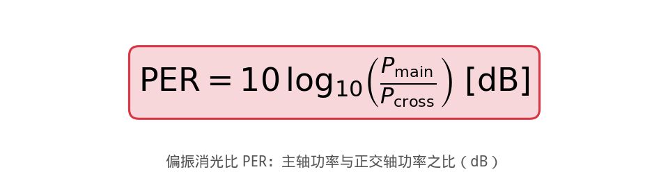
Figure 8: PER definition equation (drawn by Soar Laser)
PER is the most direct measure of PM performance. PER = 30 dB means the principal-axis power is 1000 times the orthogonal-axis power.
Polarisation crosstalk coupling model
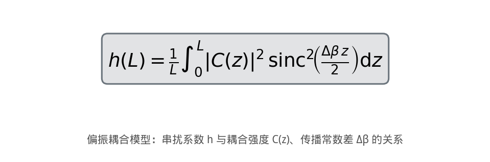
The crosstalk coefficient h describes the polarisation energy transfer per unit length. When Δβ is large enough (i.e. beat length is short enough), the sinc² function makes coupling efficiency drop sharply — the mathematical essence of high-birefringence polarisation holding.
5. Characteristic Comparison and Pros/Cons
5.1 Advantages
1. High polarisation stability: maintains polarisation under bending, vibration and temperature fluctuation, with far less PER degradation than standard SMF
2. System predictability: the slow-axis direction of a PM patch cord can be visually confirmed by the stress rods, easing system integration
3. Compatible with standard fibre components: 125 μm cladding ensures compatibility with conventional splicers and connectors
4. Multi-wavelength availability: commercial products cover the full 350 nm–2200 nm range
5.2 Limitations
1. Higher attenuation than SMF: stress-rod scattering gives roughly 4–10 times the attenuation of standard SMF
2. Requires precise alignment: input polarisation must be aligned to the fibre principal axis (1° error ≈ −35 dB added crosstalk, 5° ≈ −21 dB) [5]
3. Not for long-distance transmission: crosstalk accumulates with length, unsuitable for telecom-grade long-haul lines
4. Higher cost: both the fibre and the dedicated splicers/connectors cost more than SMF systems
5. Limited variety: not every special fibre (e.g. some active doped fibres, non-silica fibres) has a PM version
5.3 Is PM fibre necessary?
PM fibre is necessary only when the following conditions are simultaneously met [5]:
1. The source outputs linearly polarised light
2. Downstream components are polarisation-sensitive (e.g. lithium-niobate modulators, interferometers)
3. The entire optical path is PM-specification with aligned principal axes
In ordinary data communication and FTTH, the receiver does not care about input polarisation, so PM fibre is unnecessary — the most common purchasing misconception.
6. Typical Applications
6.1 Fibre-optic gyroscope (FOG) — the largest market
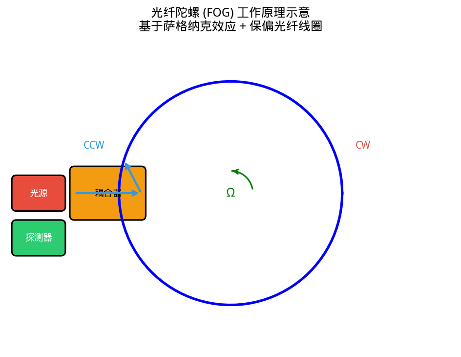
A FOG uses the Sagnac effect to measure angular velocity: two beams propagating in opposite directions around the same fibre coil acquire a phase difference proportional to angular velocity when the coil rotates. Polarisation stability directly determines bias stability and scale-factor accuracy.
– Navigation-grade FOG: requires PER ≥ 30 dB, beat length ≤ 3 mm @1550 nm, crosstalk ≤ −30 dB/km
– Tactical-grade FOG: accepts PER ≥ 20 dB, beat length ≤ 5 mm
– Modern high-precision systems have moved from 850 nm to 1310 nm and 1550 nm to exploit lower Rayleigh scattering and compatibility with erbium-doped fibre amplifiers [5][7]
6.2 Interferometric fibre sensors
Mach–Zehnder (MZI), Michelson and Fabry–Pérot (F-P) interferometric fibre sensors all need a stable polarisation state for high-contrast interference fringes. Applications include hydrophone arrays, distributed acoustic sensing (DAS) and current sensors (Faraday effect) [1][7].
6.3 PM fibre lasers and amplifiers
Seed lasers, inter-stage connections in power amplifiers and nonlinear frequency conversion (e.g. SHG, OPO) all require linearly polarised pump or signal light. PM rare-earth-doped active fibres (PM-YDF, PM-EDF) combine PM structure with gain and are key to high-power linearly polarised fibre lasers [1].
🔗 Need a PM patch cord or custom fibre component? Soar Laser offers Thorlabs full-series PM patch cords (PANDA / Bow-tie, 350–2200 nm) with customisation and splicing services — welcome to enquire.
6.4 Optical coherence tomography (OCT)
OCT sample and reference arms use PM fibre to ensure polarisation consistency, eliminating polarisation-induced signal fading and improving image signal-to-noise ratio.
6.5 Coherent optical communication and CPO/ELS
In coherent optical communication, PM fibre is used for modulator pigtails, local-oscillator paths and polarisation-diversity receivers. As AI compute demand drives CPO (Co-Packaged Optics) and ELS (External Laser Source), the need for high-density, fine-diameter PM connections is growing rapidly [10].
6.6 Quantum optics
In quantum key distribution (QKD) and quantum entanglement experiments, polarisation states carry quantum information and PM fibre is needed to preserve the fidelity of polarisation encoding.
7. Manufacturing Process and Key Techniques
7.1 Preform preparation
PM fibre preform preparation adds stress-rod integration to standard MCVD/OVD processes [6]:
– PANDA preform: two boron-doped silica rods (B₂O₃ up to 20–30 mol%) are placed in the cladding tube and assembled with the core rod, then collapsed into a solid preform
– Bow-tie preform: wedge-shaped boron-doped regions are formed using a specially designed cross-section tube or V-groove technique
Yangtze Optical uses tube chemical-vapour deposition (an MCVD variant) to make boron-doped stress rods, with boron concentration up to 30 mol% and geometric non-roundness ≤ 1.0% [11].
7.2 Drawing control
Key control points in drawing [10][11]:
– Furnace temperature stability: affects the interface quality between stress rods and cladding
– Drawing speed and tension: determine cladding diameter accuracy (±1–2 μm) and fibre geometric symmetry
– In-line monitoring: real-time measurement of cladding diameter, beat length and birefringence
7.3 Principal-axis alignment and splicing
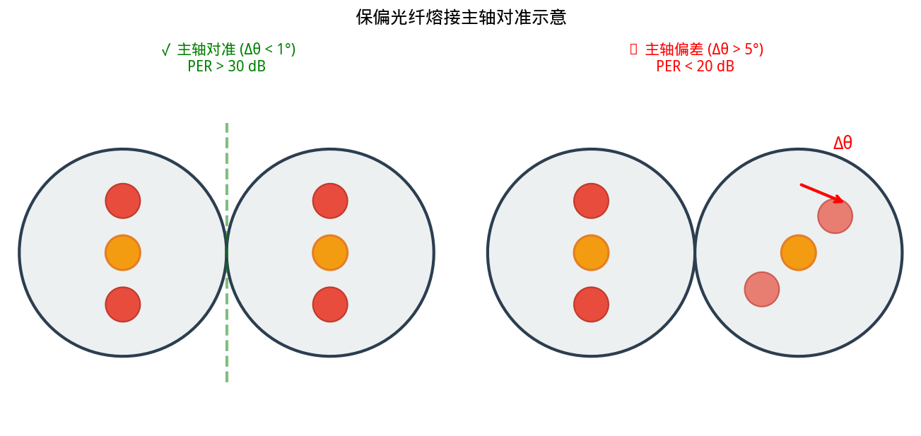
Figure 9: PM splicing requires precise principal-axis alignment — left: well aligned (PER > 30 dB), right: misaligned (PER < 20 dB)
PM splicing is far more complex than ordinary SMF [1][5]:
1. Imaging identification: the splicer must identify stress-rod positions by side imaging
2. Rotational alignment: both fibres are rotated automatically to align the stress rods, typically requiring < 0.5°–1° accuracy
3. Arc fusion: a standard arc-fusion programme runs after alignment
Effect of rotational offset on PER:
– 1° offset ≈ −35 dB added crosstalk
– 5° offset ≈ −21 dB added crosstalk
– 45° offset ≈ −3 dB (energy almost equally split, PM completely lost)
7.4 Connectorisation
Key requirements for PM connectors [1]:
– The fibre principal axis must align precisely with the connector key
– Standard convention: the slow axis aligns with the FC/APC connector key
– On mating, matching connector keys automatically maintain principal-axis continuity
– Typical PM connector PER: 22–30 dB
8. Selection Guide and Common Misconceptions
8.1 Key selection points
1. Specify the operating wavelength: the PM fibre cut-off wavelength must be below the operating wavelength. Fibre designed for 1550 nm will support higher-order modes at 980 nm and PER collapses
2. Determine the PER requirement: navigation-grade FOG needs PER ≥ 30 dB; ordinary sensing ≥ 20 dB is sufficient
3. Match the mode-field diameter: match MFD with other fibres in the system to reduce splice loss
4. Assess length and crosstalk budget: crosstalk accumulates with length; short device patch cords have far higher PER than long coils
5. Mind the bend radius: going below the minimum bend radius introduces added stress crosstalk. Typically ≥ 15 mm short-term, ≥ 30 mm long-term [5]
6. Choose PANDA vs Bow-tie: general use PANDA (good compatibility, lower cost); extremely high PER choose Bow-tie
8.2 Twelve common misconceptions
Misconception 1: PM fibre can turn any polarised light into linearly polarised light.
✗ Correct: PM fibre cannot ‘purify’ a polarisation state — it only preserves a linear state already launched along the principal axis. If the input is not linearly polarised or is not aligned to the principal axis, the output will be elliptical or random. To obtain linear output, polarisation alignment must be done at the input [1][5].
Misconception 2: PM fibre is the same as single-polarisation fibre.
✗ Correct: PM fibre transmits two orthogonal modes but suppresses coupling (‘carries two, does not mix’); single-polarisation fibre permits only one mode, the other being cut off (‘carries one’). Their physical mechanisms are completely different [1][2].
Misconception 3: PM splicing only needs core alignment.
✗ Correct: besides core-axis alignment, the principal axes of both fibres must be precisely rotationally aligned. A 1° error introduces about −35 dB crosstalk, falling to −21 dB at 5°. The much higher price of PM splicers comes precisely from this extra degree of freedom [1][5].
Misconception 4: the longer the PM fibre, the better it holds polarisation.
✗ Correct: quite the opposite. Crosstalk accumulates with length — typical PM crosstalk is on the order of −30 dB/km, meaning PER degrades by about 30 dB after 1 km. PM fibre suits short device and intra-system links rather than long-haul transmission [5][7].
Misconception 5: all single-mode fibres are PM fibres.
✗ Correct: all commercial PM fibres are indeed single-mode at their design wavelength, but the vast majority of single-mode fibres (e.g. ITU-T G.652 SMF-28) have no PM capability at all. PM is additional birefringence engineering on top of single-mode [1][5].
Misconception 6: PM fibre does not need input polarisation alignment.
✗ Correct: PM fibre only preserves a state ‘already aligned to the principal axis’. If input polarisation is at angle θ to the principal axis, PER degrades directly to 10·log₁₀(cos²θ/sin²θ). For θ = 5° the theoretical PER ≈ 21 dB; at θ = 45° PER = 0 dB (PM completely lost) [5].
Misconception 7: PM fibre can be bent freely like ordinary fibre.
✗ Correct: excessive bending introduces extra stress and increases polarisation crosstalk. Always observe the manufacturer’s minimum bend radius (typically 15 mm short-term, 30 mm long-term), avoiding clamping near connectors or bending in tight cable ducts [5].
Misconception 8: PANDA and Bow-tie are interchangeable.
✗ Correct: the working principle is the same (stress birefringence), but Bow-tie’s wedge stress regions lie nearer the core, giving higher birefringence and PER with greater splicing difficulty. Choose Bow-tie for extreme precision, PANDA for general use. They cannot simply be swapped [5][7].
Misconception 9: a higher-PER PM patch cord means better fibre quality.
✗ Correct: patch-cord PER depends not only on the fibre but also on connector alignment accuracy, end-face polish quality and test method. A 30 dB patch cord may use ordinary −30 dB/km PM fibre (which performs well at short length), while a 25 dB cord may use higher-grade −40 dB/km fibre let down by the connector. Assess the fibre crosstalk specification too [5].
Misconception 10: PM attenuation is about the same as ordinary fibre.
✗ Correct: due to stress-rod scattering, PM attenuation is typically 4–10 times that of standard SMF. PANDA PM fibre is typically 0.8–2.0 dB/km at 1550 nm, versus ≤ 0.2 dB/km for G.652 SMF — the price paid for PM function [1][5][7].
Misconception 11: the operating wavelength can be chosen freely without affecting PM performance.
✗ Correct: all PM parameters (beat length, crosstalk, cut-off wavelength, MFD) vary with wavelength. Beat length L_B = λ/B grows linearly with wavelength, i.e. effective birefringence weakens and PM ability falls at longer wavelengths. The design wavelength must be specified when selecting PM fibre [5][7].
Misconception 12: PM patch cords can be mixed freely with ordinary SMF patch cords.
✗ Correct: physically they can be spliced (same cladding diameter), but the joint loses PM function — the polarised output from PM fibre drifts randomly once it enters SMF. When the whole path needs PM, every segment (patch cords, couplers, modulator pigtails) must be PM-specification [1][5].
9. Further Reading
1. RP Photonics Encyclopedia: Polarization-maintaining Fibers — authoritative review entry
2. RP Photonics Encyclopedia: Single-polarization Fibers — distinguishing SP from PM fibre
3. RP Photonics Encyclopedia: Birefringence — fundamentals of birefringence
4. RP Photonics Encyclopedia: Polarization Beat Length — beat-length definition and calculation
5. J. Noda et al., ‘Polarization-maintaining fibers and their applications’, J. Lightwave Technol. 4(8), 1071 (1986) — classic review, doi: 10.1109/JLT.1986.1074847
6. Corning / Fujikura PANDA PM Fiber Datasheets — industry-standard PANDA product specifications
7. OCC (Optical Cable Corporation), PM Fiber Selection Guide for Gyroscope and Sensor Applications — application selection reference
8. K. Okamoto, T. Hosaka, and T. Edahiro, ‘Stress analysis and optical birefringence in elliptical-core fibers’, J. Lightwave Technol. 2(4), 432–439 (1984) — classic analysis of elliptical-core fibre
9. T. Schreiber et al., ‘Stress-induced single-polarization single-transverse mode photonic crystal fiber with low nonlinearity’, Opt. Express 13(19), 7621 (2005) — photonic-crystal PM fibre
10. Yangtze Optical, Six Series of Device PM Fibre New Product Release (2026-09-10) — latest domestic PM fibre industry development
11. Wuhan Yangtze Optical, Panda PM Fibre Product Specification for FOG Waveguides — detailed domestic PM fibre parameters
Further reading and product recommendations
Further reading
If this PM fibre article interests you, the following related articles in Soar Laser’s encyclopaedia are also recommended:
– Single-mode fibre encyclopedia — fundamentals and parameters of standard single-mode fibre
– Fibre Bragg grating encyclopedia — working principle and applications of FBGs
– Fibre coupling efficiency encyclopedia — calculation methods and optimisation strategies
Representative PM fibre product references
The following lists typical in-stock PM fibre models from Thorlabs and Yangtze Optical for selection reference. Actual prices follow official quotations.
| Manufacturer | Model | Type | Operating wavelength | Beat length | MFD | Price tier |
|---|---|---|---|---|---|---|
| Thorlabs | PM460-HP | PANDA | 460–700 nm | 1.3 mm @460nm | 3.3 μm | $35.59/m |
| Thorlabs | PM780-HP | PANDA | 770–1100 nm | 2.4 mm @850 nm | 5.3 μm @850nm | $25.42/m |
| Thorlabs | PM980-XP | PANDA | 970–1550 nm | ≤2.7 mm @980 nm | 6.6 μm | $31.79/m |
| Thorlabs | PM1550-XP | PANDA | 1440–1625 nm | ≤5.0 mm @1550 nm | 10.1 μm | $31.79/m |
| Thorlabs | HB1550T | Bow-tie | 980–1550 nm | ~3 mm @1550nm | 10.5 μm | Enquire |
| Yangtze Optical | PM15Y-80-U13 | PANDA | 1550 nm | ≤ 4.0 mm | 6.5 μm | Enquire |
Note: Thorlabs prices are from public thorlabs.com quotations (USD); Yangtze Optical specifications are from the official product manual [11]. Actual purchase prices vary with quantity and channel; the above is for reference only and is not a quotation.
Disclaimer: This article is compiled from RP Photonics Encyclopedia, public manufacturer specification sheets and academic literature, for technical reference only. Product parameters follow the maker’s latest datasheet. As an optical component supplier, Soar Laser can provide PM patch-cord customisation and optical system consultation — please contact us to learn more.
Leave a Reply