


html
Polarisation Rotator Encyclopedia:
Principles, Structures and Selection of Faraday Rotators, Mechanically Rotated Half-Wave Plates and Liquid-Crystal Polarisation Rotators
One function, three technical routes — from the magneto-optic non-reciprocal effect to electrically controlled birefringence, explaining the physics of polarisation-plane rotation, material systems and engineering selection
1. Definition of Terms and Basic Concepts
A polarisation rotator is an optical device that rotates the azimuth of the plane of linearly polarised light in a controlled way: the input is linearly polarised light and the output remains linearly polarised, but the polarisation direction is rotated through a defined angle relative to the input. An ideal polarisation rotator changes only the ‘pointing’ of the polarisation plane — not the intensity (apart from insertion loss), not converting linear polarisation into elliptical, and not changing the beam’s direction of propagation.
Why is rotating the polarisation plane needed in engineering? A laser’s output polarisation direction is set by the cavity design and gain medium and is usually fixed (commonly horizontal), while practical applications impose their own requirements on polarisation azimuth:
- Processes are sensitive to polarisation direction. In laser cutting of carbon steel and stainless steel, kerf width, dross and cutting speed vary with the azimuth of polarisation relative to the feed direction — absorption is highest when the electric-field vector is parallel to the cutting front, so optimising cut quality often requires rotating the polarisation plane to the target azimuth; in welding, polarisation azimuth likewise affects energy coupling into the melt pool.
- Polarisation-state alignment before polarisation beam combining/splitting (Polarisation Beam Combiner/Splitter, PBC/PBS). The polarisations of two beams must be strictly orthogonal and aligned respectively to the p- and s-axes of the splitting interface; a 1° azimuth error causes appreciable combining loss and crosstalk.
- Polarisation matching in interferometry, holography and heterodyne detection. A mismatch between reference and signal polarisation states directly reduces fringe contrast or even prevents interference altogether.
- Return-light isolation requires non-reciprocal rotation. Amplifiers, seed sources and ultrafast oscillators are extremely sensitive to backward return light, which causes mode hopping, frequency pulling and even facet damage; blocking return light relies on ‘non-reciprocal’ polarisation rotation — something only the Faraday effect can provide.
To deliver the function of ‘rotating the polarisation plane’, industry has three mainstream technical routes. An overview comparison follows, with each developed in parallel in the sections below:
| Technical route | Physical mechanism | Reciprocity | Rotation angle | Drive method | Typical power level and use |
|---|---|---|---|---|---|
| Faraday rotator | Magneto-optic effect (magnetic-field-induced circular birefringence) | Non-reciprocal: the plane rotates in the same sense in both directions, giving 90° for a round trip | Fixed 45° (set at manufacture, typical tolerance ±1°–±3°) | Passive (permanent magnet) | Sleeve devices from a few to tens of watts; high-power isolators from hundreds of watts to kilowatts; optical isolators, circulators, return-light blocking |
| Mechanically rotated half-wave plate | Crystal birefringent phase retardation | Reciprocal: the polarisation plane is restored on the return trip | Continuously adjustable, polarisation plane 0–180° (plate turns θ, plane turns 2θ) | Manual dial or motorised rotation stage | Highest power handling of the three (hundreds of watts to kilowatts available); cutting/welding polarisation adjustment, combining alignment, power splitting |
| Liquid-crystal polarisation rotator (LCPR) | Electrically controlled birefringence (field alignment of nematic liquid-crystal molecules) | Reciprocal: restored on the return trip | Continuously voltage-adjustable (over 180°) or two-state twisted-nematic 0°/90° switching | Programmable voltage (controller required) | Low, practical mostly at milliwatt to few-watt levels; laboratory automated polarisation scanning, closed-loop polarisation control, imaging and measurement |
Distinguishing aliases and related terms is where procurement and engineering communication most often go wrong:
- Polarisation rotator vs polarisation controller. In industry usage the latter usually means a fibre-based device (three-paddle, piezo-squeezer types) that introduces controlled birefringence in fibre to transform any input polarisation state into any output state (often elliptical); a free-space polarisation rotator only rotates the azimuth of the plane of linear polarisation while preserving linearity. The two belong to separate selection systems — fibre systems versus free-space paths — and cannot substitute for each other.
- Faraday rotator vs Faraday optical rotator. Two Chinese translations of the same device (Faraday Rotator), with no substantive difference. Note, however, that natural optical activity in chemistry (e.g. quartz crystal, sugar solution) is reciprocal — the rotation cancels on a round trip — whereas Faraday rotation is non-reciprocal — the rotations add on a round trip. Both carry the word ‘rotation’, yet the physical properties are opposite; this is the most common conceptual trap.
- Quartz natural-optical-activity polarisation rotators (fixed angle). Besides the three adjustable routes discussed here, passive fixed-angle quartz rotators are also available (using the intrinsic optical activity of α-quartz, reciprocal, magnet-free, high damage threshold), suited to high-power fixed-angle rotation and depolarisation compensation in laser resonators; the angle is fixed by crystal thickness and cannot be electrically adjusted, so they fall outside the three routes covered here.
- Rotator vs waveplate/retarder. A waveplate’s intrinsic function is to introduce phase retardation between ordinary (o) and extraordinary (e) rays, changing the shape of the polarisation ellipse; only a half-wave plate (HWP), used in the specific configuration of mechanical rotation, produces rotation of the polarisation-plane azimuth. A quarter-wave plate (QWP) converts linear↔circular polarisation and does not rotate the polarisation plane.
- Optical rotator vs image rotator. The latter refers to devices such as Dove prisms and Pechan prisms that rotate the orientation of an image, unrelated to polarisation — do not confuse them when purchasing.
- Division of labour with the polariser. A polariser performs passing and analysing and is a component that ‘selects’ (absorbing types lose about half the energy, beam-splitting types divide light into two paths); a rotator does not select energy, it only changes polarisation direction. The two are often used together: the rotator ‘turns’, the polariser ‘selects’. An optical isolator is precisely a combination of ‘polariser + Faraday rotator + polariser’.
Their division of labour can be summed up in a motto: polariser = filter (blocks light of the wrong direction), waveplate = shaper (reshapes only the polarisation form), rotator = steerer (turns only the polarisation plane to the target azimuth).
2. Working Principles
2.1 Faraday rotators: the magneto-optic effect and non-reciprocity
The Faraday effect was discovered by Michael Faraday in 1845: when linearly polarised light travels along a magnetic field through a magneto-optic medium placed in that field, its plane of polarisation rotates. It was one of the earliest experimental proofs of an intrinsic link between light and electromagnetism. Its physical essence is magnetic-field-induced circular birefringence: with a field applied along the propagation direction, the medium presents different refractive indices to left- and right-circular components, n₊ ≠ n₋; the two equal-amplitude circular components travel at different speeds and accumulate a phase difference Δφ, so the recombined linear polarisation plane rotates by β = Δφ/2. The rotation angle is given by:
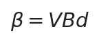
Faraday rotation angle: β is the polarisation-plane rotation angle (radians), V the Verdet Constant (rad/(T·m), determined by material and wavelength), B the magnetic flux density along the propagation direction (T), and d the propagation length in the magneto-optic medium (m)
The derivation chain from circular birefringence to β=VBd is: the two circular components accumulate a phase difference Δφ = (2πd/λ)(n₊−n₋) over length d, the linear plane rotates by half of it, β = Δφ/2 = (πd/λ)(n₊−n₋); under a magnetic field n₊−n₋ is proportional to B, defining V = (π/λ)(n₊−n₋)/B, giving β = V·B·d.
Note that the rotation angle depends only on material, magnetic field and length — independent of the input polarisation’s initial azimuth and of light intensity. The sign of V relates to the material’s magnetism: paramagnetic materials (TGG, TSAG, terbium glass containing rare-earth ions such as Tb³⁺, Ce³⁺) have negative V, diamagnetic materials (fused silica, BK7 and other ordinary glasses) have positive V one to two orders of magnitude smaller; ferromagnetic/ferrimagnetic materials (YIG and others) rotate very strongly at saturation but are usually described by rotation per unit length (°/cm) rather than V (β=VBd applies only in the paramagnetic/diamagnetic linear regime and no longer holds once YIG is magnetically saturated). The sign of V merely indicates the handedness of rotation; engineering calculations use the absolute value |V|, and most manufacturers’ data sheets quote positive values.
Non-reciprocity is the soul of this route. The direction of rotation is set by the magnetic-field direction, not by the direction of light propagation: the handedness of the rotation is defined ‘around the magnetic-field vector’, so whichever end the light enters, it rotates in the same handedness. Light passing forwards rotates 45°, and after reflection passes back through, rotating a further 45° in the same sense for 90° on the round trip; in a reciprocal device such as a half-wave plate the forward and reverse rotations cancel and the polarisation plane is restored.
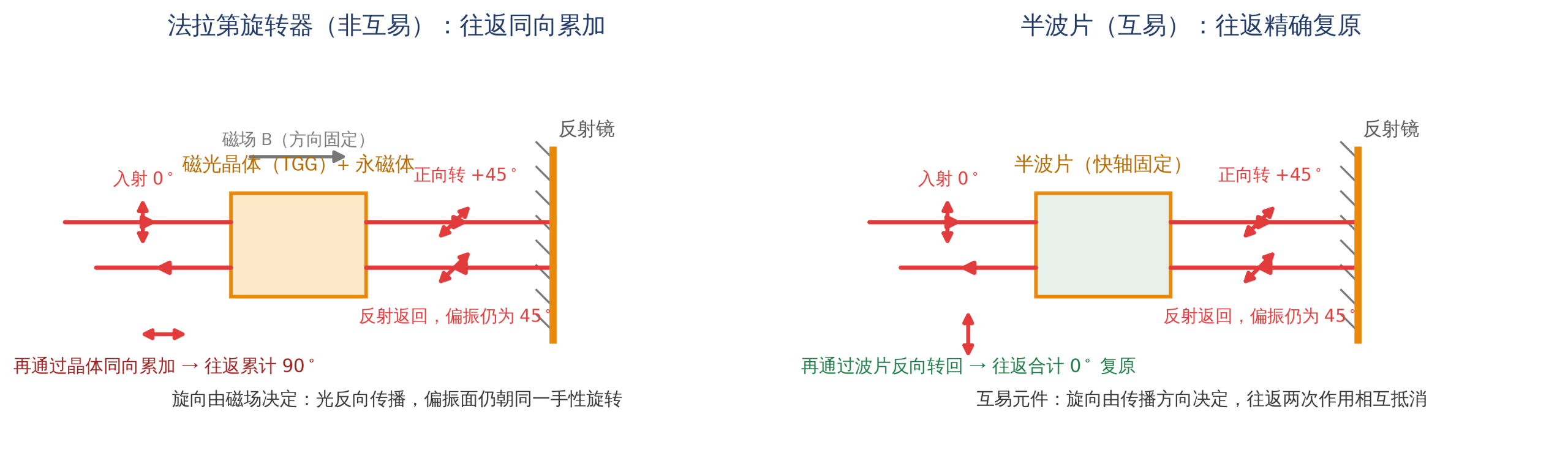
Schematic of a Faraday rotator’s non-reciprocal round-trip path: forward passage rotates the plane 45°, reflection and return rotation add another 45° in the same sense for 90° round trip; compared with a reciprocal waveplate restoring the plane
Source: drawn by Changsha Soar Laser
| Component passed through | One forward pass | One reverse pass after reflection | Round-trip total |
|---|---|---|---|
| 45° Faraday rotator (non-reciprocal) | +45° | a further +45° (adds in the same sense) | 90° |
| Half-wave plate with fast axis at 22.5° (reciprocal) | +45° | −45° (exactly restored) | 0° |
This is exactly how an optical isolator works: the input polariser and output analyser have transmission axes at 45° to each other. Forward light is rotated 45° by the Faraday rotator and thus aligned with the analyser axis and transmitted; backward stray light is rotated a further 45° in the same sense, becoming 90° orthogonal to the input polariser axis and blocked.
Annotating the path like an account book (input polariser axis at 0°, analyser axis at 45°): forward — 0° light exits the polariser → Faraday rotator turns 45° → 45° polariser transmits fully → reaches the mirror; return — 45° light reflects back → turns a further 45° in the same sense → accumulates 90° → blocked orthogonal to the 0° polariser. Replace the Faraday rotator with a half-wave plate whose fast axis is at 22.5° and the round-trip rotation cancels, the returned light remains at 0° and is fully transmitted — the contrast showing why reciprocal devices cannot provide isolation.
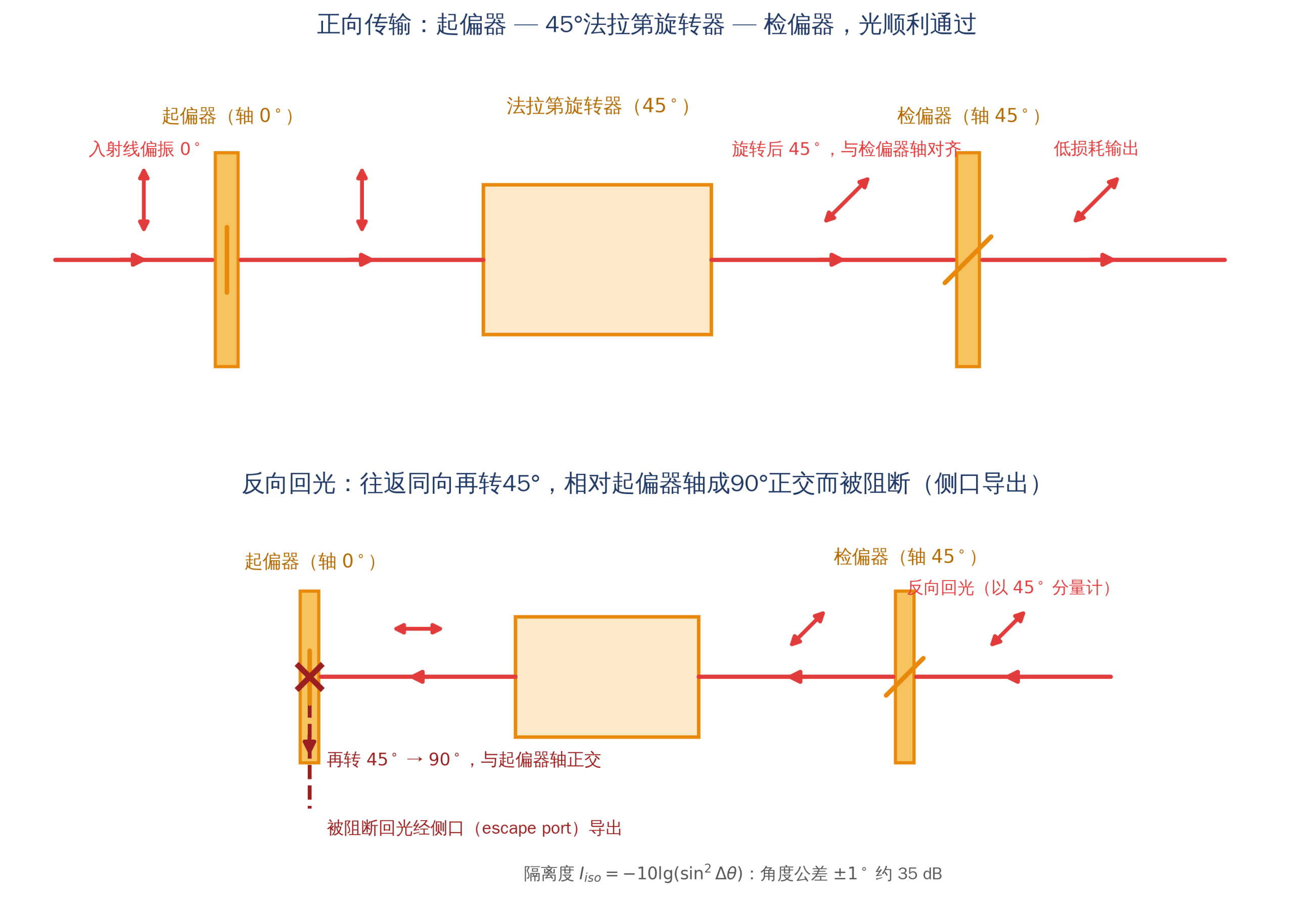
Optical isolator principle: polariser — 45° Faraday rotator — analyser (axes at 45°), forward light passes, return light accumulates 90° on the round trip and is blocked by the polariser
Source: drawn by Changsha Soar Laser
Deviation of the rotation angle from 45° directly degrades isolation. For a polarisation-dependent isolator the relation between rotation-angle error Δθ (degrees) and isolation can be approximated as:

Isolation versus rotation-angle error: I_iso is isolation (dB), Δθ the deviation of the actual rotation angle from 45°. Δθ=1° gives about 35 dB, 0.5° about 41 dB, and 3° only about 26 dB — this is why industrial devices control angle tolerance to ±1°–±3° at manufacture. Note these figures are the theoretical upper limits assuming infinite polariser extinction, no thermal depolarisation and zero assembly error; real isolation is further constrained by prism extinction ratio, crystal thermal depolarisation and assembly error, and measured values are lower
Material and wavelength dependence of the Verdet constant. V increases markedly at shorter wavelengths: away from electronic absorption bands it follows roughly a 1/λ² law (because circular-birefringence phase difference is proportional to wavenumber, with resonant dispersion further enhancing it), and grows faster near rare-earth absorption bands. Taking TGG (terbium gallium garnet, Tb₃Ga₅O₁₂) as an example, its Verdet constant is about −134 rad/(T·m) at 632.8 nm, about −190 rad/(T·m) at 532 nm, and falls to about −40 rad/(T·m) at 1064 nm (widely cited typical measured values). This means about 2 cm of TGG is needed for a full 45° at 1064 nm with a 1 T field, versus only about 6 mm at 632.8 nm — near-IR Faraday devices are generally bulkier and longer than visible ones. Common magneto-optic materials are compared below:
| Material | Typical V / rotation capability | Applicable band | Thermal and optical characteristics | Positioning |
|---|---|---|---|---|
| TGG (terbium gallium garnet) | −134 rad/(T·m)@632.8 nm; −40@1064 nm | about 400–1100 nm (excluding the Tb³⁺ absorption band around 470–500 nm), extendable to about 1500 nm | thermal conductivity about 7.4 W/(m·K), residual absorption on the order of 10⁻³ cm⁻¹, high damage threshold, good optical quality | The most mainstream material in the visible–near-IR and the best-balanced for cost/performance |
| TSAG (terbium scandium aluminium garnet) | V about 20% higher than TGG (about 48 rad/(T·m) at 1064 nm) | same window as TGG | lower absorption and smaller thermally induced birefringence | shorter crystal and smaller magnet possible, for high-power and miniaturised devices |
| TAG (terbium aluminium garnet) and TAG ceramics | V about 1.3 times TGG | visible–near-IR | single crystal is incongruently melting and hard to grow; transparent ceramic processing can produce it | high-power-potential material, mainly the ceramic route |
| CeF₃ (cerium fluoride) and other fluoride crystals (KTF, LiTbF₄, etc.) | V of the same order as TGG (higher in the UV–visible) | UV–visible to near-IR (about 400 nm–1.5 μm) | lower absorption and thermo-optic coefficient (some types about an order of magnitude below TGG) | a new direction for UV windows and high average power |
| Terbium glass / magneto-optic glass | V markedly lower than TGG (about 1/2 to a few fractions of TGG) | broad (visible–near-IR) | low cost, large apertures possible, poor thermal conductivity | large-aperture, low-power, cost-sensitive applications and current sensing |
| YIG (yttrium iron garnet) / Bi-doped BIG | ferromagnetic, specific rotation about 150–280 °/cm (1310/1550 nm), Bi doping can reach several hundred °/cm or more | above about 1100 nm (opaque to visible) | thin film (liquid-phase epitaxy, LPE) rotates 45° in a few hundred micrometres, very compact | the mainstay of fibre-communication isolators, circulators and Faraday rotator mirrors |
Temperature dependence and high-power thermal depolarisation. The Verdet constant of paramagnetic materials such as TGG decreases with rising temperature (paramagnetic susceptibility roughly follows Curie’s law), with a typical relative temperature coefficient of about −0.04%/℃ near room temperature (order 10⁻⁴/℃); permanent-magnet remanence also has a temperature coefficient (NdFeB typically about −0.1%/℃). Devices are usually calibrated at room temperature (about 22 ℃), so the rotation angle drifts when ambient temperature departs significantly. The real limit on high-power use is thermal depolarisation: residual absorption in the crystal creates a radial temperature gradient, high in the centre and low at the edge, across the illuminated aperture, producing a thermal lens (wavefront distortion, focus drift) and, via the photoelastic effect, inducing parasitic linear birefringence (stress birefringence). This thermally induced birefringence lets part of the light ‘leak’ into the orthogonal polarisation (depolarisation ratio γ), directly lowering isolation — above a few hundred watts of average power, isolation is determined almost entirely by thermal depolarisation rather than angle error.
The industry’s countermeasures form a combined set: ① material upgrade — TSAG, TAG ceramics and fluoride crystals (KTF etc.) with higher V, lower absorption and better thermo-optic properties; a larger V means a shorter crystal and less total absorbed heat; ② shorter crystal + stronger magnetic field, reducing absorption length; ③ depolarisation-compensation design — typically inserting a reciprocal optical-activity element between two magneto-optic crystals (each rotating 22.5°), a 45° quartz rotator (natural optical activity), so that the thermal-birefringence axes in the second crystal are rotated 90° relative to the first and the induced depolarisation of the two sections cancels (this ‘dual crystal + intermediate 45° reciprocal quartz rotator’ configuration is the Khazanov compensation scheme). Note that a half-wave plate is a phase-retardation device producing a mirror flip of polarisation and cannot satisfy the condition of rotating the thermal-birefringence coordinate frame; it can be used in other dual-crystal Faraday architectures (e.g. forward polarisation restoration) but is not a standard element of Khazanov thermal-depolarisation compensation; literature reports compensated isolators maintaining about 30 dB at kilowatt average power, whereas single-crystal TGG devices are practically limited to a few hundred watts; ④ heat dissipation and geometric design — larger aperture to lower power density, forced cooling or water cooling of end/side faces, thin-plate crystal geometry. When selecting a high-power device, check at what isolation its stated average power is specified, whether it is a compensated design, and its cooling and mounting-orientation requirements.
Fixed 45° design and adjustability. Industrial Faraday rotators are set to 45° at manufacture by selecting crystal length and field strength, with typical tolerance ±1°–±3°, because an isolator needs exactly 45°. Some special tunable models (e.g. Thorlabs tunable broadband isolators, Leysop tunable series) allow the TGG rod to slide axially in the magnet cavity to fine-tune the effective interaction length (a tuning ring changes the length of crystal inserted into the magnet), adapting to neighbouring wavelengths within the design band or compensating temperature drift; but the vast majority of standard commercial isolators have a fixed crystal assembly with no such mechanism, and the fine-tuning range is limited, so they cannot be used as continuously adjustable rotators.
2.2 Mechanical half-wave plate rotation: birefringence and the 2θ relation
In uniaxial crystals such as quartz, MgF₂ and sapphire, the o- and e-ray refractive indices differ (no ≠ ne); after passing through a crystal of thickness d the two components accumulate a phase retardation:
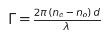
Waveplate retardation: Γ is the phase difference between o and e rays, n_e and n_o the e- and o-ray indices, d the crystal thickness, λ the wavelength; a half-wave plate satisfies Γ = π (optical path difference λ/2), a quarter-wave plate Γ = π/2
The 2θ relation and its derivation. A half-wave plate reverses the phase of the slow-axis component (a π shift), equivalent to reflecting the polarisation direction mirror-symmetrically about the fast axis. In Jones-matrix terms with the fast axis along x, J = diag(1, −1), so an input vector (cosθ, sinθ) emerges as (cosθ, −sinθ), i.e. the azimuth changes from +θ to −θ. With plate fast-axis azimuth φ and input polarisation azimuth α, the output azimuth is α′ = 2φ − α:

Half-wave plate polarisation-plane rotation relation: α is the input polarisation azimuth, φ the plate fast-axis azimuth, α′ the output polarisation azimuth; mechanically rotating the plate by Δφ rotates the plane by 2Δφ (this doubling refers to the change: with input polarisation fixed, turning the plate 10° turns the plane 20°; the absolute output azimuth is still given by α′=2φ−α). Rotating the plane by 90° requires turning the plate only 45°
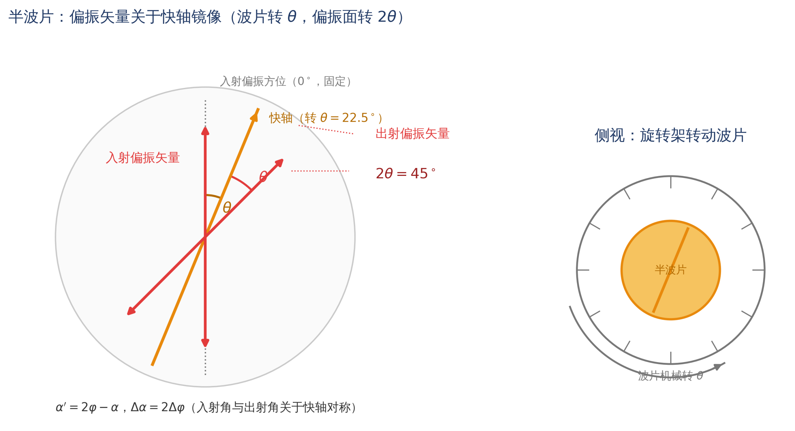
Half-wave plate 2θ relation: input linear polarisation is mirror-flipped about the fast axis; turning the plate fast axis by θ rotates the plane by a total of 2θ
Source: drawn by Changsha Soar Laser
This 2× amplification is both the convenience of a half-wave-plate rotator for fine adjustment (a small mechanical change doubles as polarisation adjustment) and the most common on-site mistake — when controlling a motorised stage, the ‘target polarisation angle’ must be divided by 2 before being sent to the motor. In terms of reciprocity, the half-wave-plate Jones matrix satisfies J·J = I (applying the same rotation twice returns the identity matrix), so a round trip through the same plate exactly restores the polarisation state, the opposite of a Faraday rotator — which is why a waveplate can never block return light.
Wavelength dependence and waveplate construction. Γ is proportional to 1/λ (Δn itself has dispersion but weaker), so a half-wave plate satisfies Γ = π strictly only at the design wavelength; away from it the output degrades to elliptical polarisation, seen as poorer extinction ratio and increased combining crosstalk. Temperature and incidence angle also affect retardation through d and Δn, with greater sensitivity for thicker plates. By construction, waveplates fall into the following categories:
| Waveplate type | Construction | Retardation accuracy and stability | Damage threshold | Typical application |
|---|---|---|---|---|
| Multiple-order waveplate | single crystal, thickness giving Γ = (2m+1)π (m large) | low cost, but most sensitive to wavelength, temperature and incidence angle | high (monolithic crystal) | budget-sensitive, single wavelength, stable-environment simple paths |
| True zero-order waveplate | single ultrathin crystal, thickness exactly λ/(2Δn) (quartz about 60 μm at 1064 nm) | best temperature/angle/wavelength stability; but wafer extremely thin, hard to process and mount, low mechanical strength | high | wide-temperature, wide-angle, high-precision applications |
| Cemented zero-order waveplate | two multiple-order plates with crossed optical axes, cemented, net retardation the difference (λ/2) | stability close to true zero-order, moderate cost; cement layer within the clear aperture | medium (cement limits power) | industrial mainstream, medium-low power |
| Air-spaced zero-order waveplate | two multiple-order plates with crossed axes, metal spacer maintaining an air gap, cement only outside the aperture | stability close to true zero-order; no cement in the optical path | highest (about 10 J/cm²@10 ns@1064 nm pulsed, CW order 2 MW/cm²) | first choice for high-power lasers (cutting/welding) |
| Achromatic waveplate | quartz + MgF₂ (two birefringent materials of different dispersion) giving net retardation ≈π over a broad band | maintains λ/2 over a wide spectrum (hundreds of nm); monochromatic precision slightly below single-wavelength zero-order | medium–high | shared multi-wavelength paths, femtosecond broadband, tuneable lasers |
In materials: crystalline quartz is low-cost, mature in processing and covers UV to near-IR, the most common substrate; MgF₂ has good UV transmission and large birefringence, the standard pairing material for achromatic waveplates and also used in deep UV; sapphire has high mechanical strength and good thermal conductivity for harsh environments; polymer zero-order waveplates are cheap and can be made large-aperture but have low damage threshold, limited to low power. Reference birefringence values at 633 nm: quartz about 0.009, MgF₂ about 0.012, sapphire about 0.008; a larger Δn means a thinner wafer for the same retardation, which is why MgF₂ suits thin zero-order and achromatic elements.
Mechanical implementation: manual and motorised rotation schemes. A waveplate mounted in a precision rotation holder allows continuous scanning of the polarisation plane. Manual schemes are holders with graduated dials (typically 1°–2° divisions, down to about 0.1° with a vernier or micrometer), low cost and suitable for one-off alignment; motorised schemes use a stepper or servo motor driving the plate mount via worm/gear reduction, with an encoder for closed-loop control, giving repeatable positioning on the order of 0.01°–0.1°, but adjustment is at second-level speed (single steps to tens of degrees per second), and gear transmission has backlash — the same dial reading corresponds to different actual angles when reversing direction, so programmatic control should use ‘one-direction approach’ or software backlash compensation. Piezo rotation stages are faster (millisecond level) but have small travel (usually only a few to a dozen degrees) and cannot cover the full range. On high-power cutting heads prefer an air-spaced zero-order waveplate with sealed protection to keep dust and spatter off the optical faces.
2.3 Liquid-crystal polarisation rotators: electrically controlled birefringence
Physical basis of nematic liquid crystal. Liquid-crystal molecules are long rods combining the fluidity of a liquid with the orientational order of a crystal. The cell consists of two glass substrates coated with transparent ITO electrodes; an alignment layer on the inner faces (rubbed polyimide) anchors the molecules parallel to the rubbing direction through anchoring. The molecules have dielectric anisotropy: once the applied voltage exceeds a threshold (order 1–2 V), positive liquid-crystal molecules tend to stand up along the field, reducing the projection of their optical axis in the beam propagation direction and hence the effective birefringence — higher voltage, smaller Δn_eff, smaller retardation, approaching zero at saturation. Retardation is a nonlinear function of voltage and must be calibrated point by point (manufacturers usually supply a voltage table for each 10° of azimuth). Drive must use a 1–2 kHz AC square wave: DC drive causes ion migration, double-layer charge accumulation and material ageing.
A single liquid-crystal variable retarder (LCVR) changes the ellipticity of polarisation, it is not itself a rotator. Commercial liquid-crystal polarisation rotators mainly use three architectures, which must be distinguished when purchasing:
| Architecture | Construction and principle | Rotation capability | Response time | Key constraints |
|---|---|---|---|---|
| Continuous LCPR (LCVR + quarter-wave plate) | A compensated LCVR combined with a zero-order polymer QWP: LCVR fast axis at 45° to the QWP slow axis, input linear polarisation parallel to the QWP slow axis; the LCVR first creates elliptical polarisation according to voltage, the QWP then restores linear, with rotation angle equal to half the change in LCVR retardation | continuous over 180° | typical average 10–30 ms (slower for small angles) | standard supply excludes input polariser; input polarisation must align precisely to the reference axis; polarisation purity typically about 150:1, transmission for polarised input >92% |
| Twisted-nematic two-state type (TN Rotator) | the liquid-crystal layer twists 90° through its thickness; at zero voltage the adiabatic-following condition holds and the plane follows the molecular twist through 90° (output orthogonal to input); with voltage the molecules stand up, the twist disappears and the plane is not rotated (output parallel to input) | 0°/90° two-state switching | ≤5 ms in the visible (selection guides 5–15 ms) | only two states, forming a fast optical switch with a polariser; contrast about 500:1 |
| High-speed LCVR / ferroelectric liquid crystal (FLC) | thin-cell high-speed nematic material with transient nematic effect (TNE) drive; or ferroelectric liquid-crystal bistable switching | continuous (LCVR) / two-state (FLC) | high-speed LCVR rise about 50 µs, fall about 500 µs@532 nm; FLC sub-millisecond | still slower than electro-optic modulators (nanosecond); FLC travel and temperature range limited |
There is another class of multi-cell cascaded modules (several low-twist cells combined or dual LCVR in cascade), synthesising a rotation matrix from the retardance of each cell to achieve achromatic polarisation rotation over a broad band or accept looser input-polarisation conditions; some products build a polariser into the liquid-crystal assembly, claiming linearly polarised output for any input polarisation — in essence ‘built-in polariser + liquid-crystal rotation unit’, where energy is selected by the polariser (half the power lost for unpolarised input), very different from the LCVR+QWP architecture (input must be precisely linear, energy not selected) in loss and alignment difficulty, so confirm the underlying architecture when purchasing.
Response mechanism and timing expectations. Liquid-crystal response has two directions: applying voltage, the field exerts torque on molecular dipoles and molecules turn quickly (turning time shortens with overdrive voltage); removing/reducing voltage, there is no external torque and molecules relax slowly through alignment-layer anchoring and elastic restoring force, so turn-off (relaxation) is usually slower than turn-on. Continuous LCPR response also depends on the size of rotation — small-angle rotation needs a smaller field change and relaxes more slowly. The scaling relation for relaxation time is:
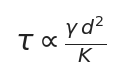
Liquid-crystal relaxation-time scaling: τ is response time, γ the rotational viscosity, d the cell thickness, K the elastic constant; response time scales with the square of cell thickness, so thin cells are much faster (high-speed devices use thin cells + high-birefringence material). Higher temperature lowers viscosity and speeds response, but also reduces birefringence. This scaling applies to ordinary nematic liquid crystal without overdrive; transient nematic effect (TNE) overdrive can break this scaling for faster switching
In engineering the transient nematic effect (TNE) can accelerate switching: at the moment of switching, cut power completely for a short instant so molecules relax naturally at their fastest, then restore the holding voltage once near the target retardation, compressing large-angle switching from tens of milliseconds to a few milliseconds. Overall liquid-crystal response lies in the microsecond-to-millisecond range: continuous type (10–30 ms) is about six orders of magnitude slower than a Pockels cell (nanosecond), high-speed LCVR (microsecond) three to four orders slower. Liquid-crystal devices are reciprocal (cannot isolate), retardation is sensitive to wavelength and temperature (calibrated at a specified wavelength within 450–1800 nm, typical operating temperature 0–50 ℃, precision applications use a temperature-controlled driver), and having no moving parts, no wear or vibration, with remote programmability and closed-loop integration, is their core value.
3. Structure and Classification
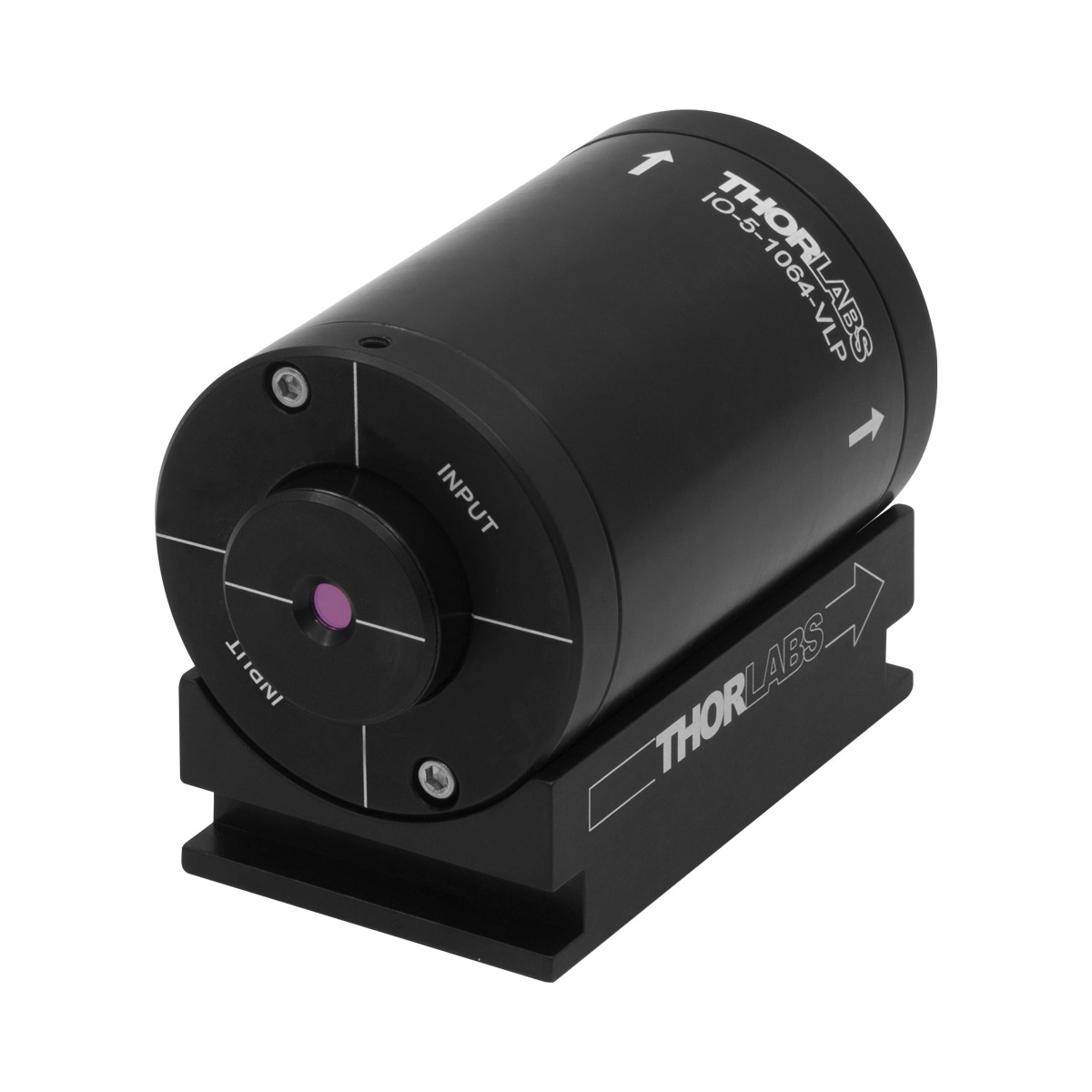
A Faraday rotator typically comprises four parts: ① permanent-magnet circuit — ring NdFeB or SmCo magnet assemblies (often complex multi-piece arrangements rather than a single magnet ring), providing a uniform strong field along the optical axis (typically order 0.5–1 T in the crystal region), requiring no power and generating no heat; ② magneto-optic crystal — a TGG rod (or TSAG, magneto-optic glass, etc.), with length determined by β = VBd = 45°; ③ end-face treatment — crystal input and output faces ground with a 1°–2° wedge and AR-coated, with polarisers in the isolator likewise at 1°–2° off normal incidence, deflecting residual AR reflection out of the path to suppress parasitic etalon effects and back-reflection between parallel faces; ④ housing and interface — an aluminium sleeve with the rotation-direction arrow engraved on the body (the basis for installation and reading the rotation sense), predominantly SM1 (1.035″-40) threading for direct integration with lens tubes and cage systems. Because of the strong internal magnet, ferromagnetic objects and magnet-sensitive equipment (hard disks, mechanical watches, magnetic cards, CRTs, pacemakers) must keep a safe distance: sleeve devices typically require ≥2 inches (about 5 cm), small packages about 1 inch; refer to the manufacturer’s specification.
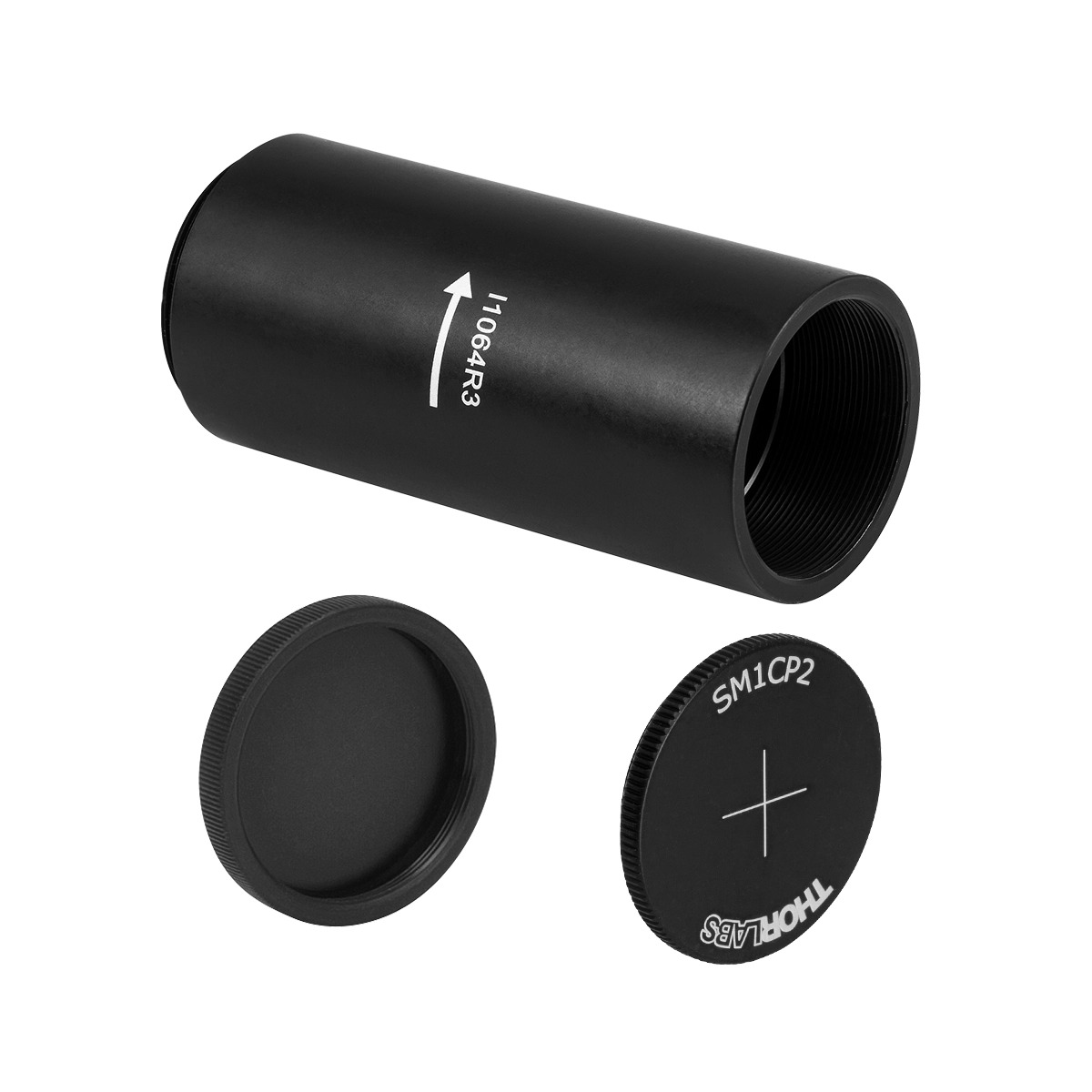
Photograph of a sleeved Faraday rotator: SM1-threaded package with the rotation-direction arrow engraved on the housing
Source: Thorlabs
Faraday devices can be subdivided by function into four categories:
- Standalone Faraday rotator. Performs only 45° non-reciprocal rotation, contains no polariser and provides no isolation by itself; used for user-assembled paths or experimental purposes. Commercial sleeved products are supplied at discrete centre wavelengths (over 20 wavelength points from 405 to 2050 nm), common apertures Ø3 mm and Ø5 mm, with compact small packages down to Ø1.8 mm beam diameter and power at the hundred-milliwatt level.
- Polarisation-dependent optical isolator (free space). Polariser + Faraday rotator + analyser (two polarisation axes at 45°), for linearly polarised paths; polarising elements are commonly Glan-Taylor prisms or thin-film polariser cubes, with blocked return light diverted through an escape port. Single-stage isolation typically 30–40 dB, dual-stage (two stages in series) 45–55 dB.
- Polarisation-independent optical isolator. The mainstream form in fibre communications: input light is first split into o and e beams by a birefringent wedge/polarisation-splitting element, both rotated 45° by the Faraday rotator, then recombined by a second splitting element; forward beams merge into the output, while reverse beams are spatially walked off out of the coupling path. Any input polarisation state can be isolated; common 1310/1550 nm pigtailed packages with single-stage isolation ≥30 dB.
- Optical circulator and Faraday rotator mirror (FRM). A circulator is a multiport (commonly three-port) non-reciprocal device routing light 1→2, 2→3, 3→1, used in fibre amplifiers, bidirectional transmission and optical sensing; an FRM integrates a 45° Faraday rotator with a mirror, giving 90° total round-trip rotation so the reflected polarisation is orthogonal to the input, widely used in interferometers and fibre sensing to eliminate polarisation fading.
A derivative of the Faraday route is the Faraday modulator: an alternating-current coil replaces the permanent magnet, making the polarisation angle oscillate periodically with drive current, used for polarisation detection, intensity modulation and fibre current sensing.
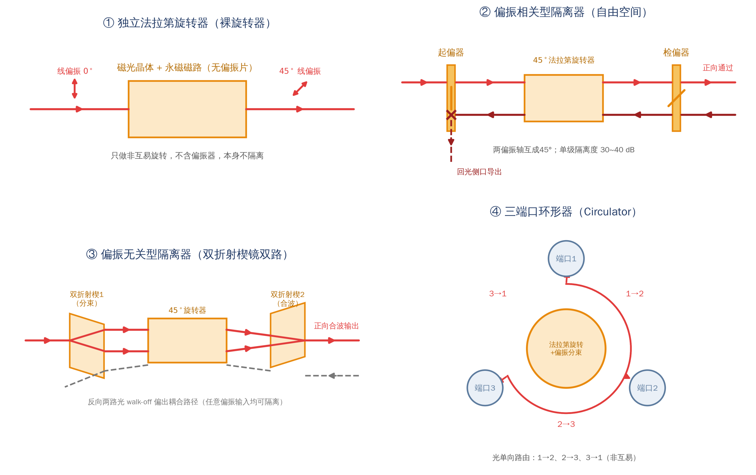
Functional classification of Faraday devices: standalone rotator, polarisation-dependent isolator (polariser+rotator+analyser, return light via escape port), polarisation-independent isolator (birefringent split+rotation+recombination), three-port circulator
Source: drawn by Changsha Soar Laser
Photograph of a free-space optical isolator: central Faraday rotator with polariser units at both ends, blocked return light exiting the side port
Source: Thorlabs
Mechanically rotated half-wave plate construction = half-wave plate (multiple-order/true zero-order/cemented zero-order/air-spaced zero-order/achromatic, commonly quartz, MgF₂, sapphire, polymer) + rotation mount (manual graduated dial or motorised stage/stepper motor, with optional encoder, limits and closed loop) + mounting interface (cage, holder, SM1 threaded ring).
Liquid-crystal polarisation rotator construction = liquid-crystal cell (optical-grade fused-silica substrate + ITO transparent electrode + polyimide alignment layer + nematic liquid-crystal layer, optionally combined with a birefringent-polymer quarter-wave film) + drive controller (1–2 kHz AC square wave, analogue or digital USB/BNC interface, optional temperature control), available as free-space discs (common outer diameters Ø25.4 mm/Ø50.8 mm/Ø76.2 mm) and fibre-pigtailed versions.
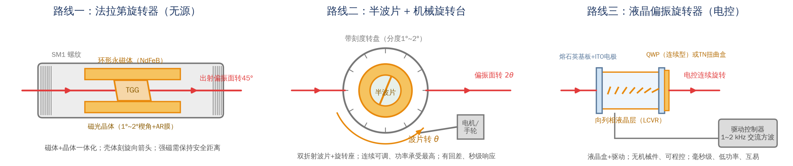
Typical construction of the three routes: Faraday rotator (permanent magnet + magneto-optic crystal + wedged AR faces), half-wave plate rotation mount (birefringent waveplate + rotation stage), liquid-crystal polarisation rotator (LC cell + drive controller)
Source: drawn by Changsha Soar Laser
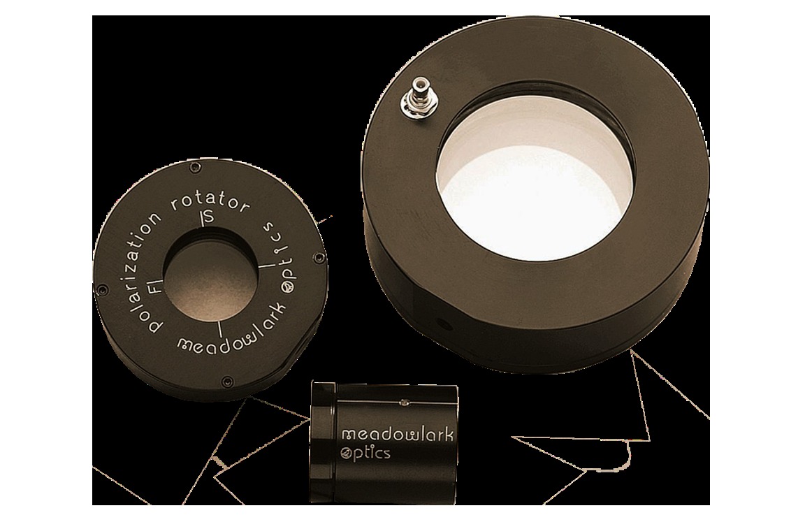
Photograph of a continuous liquid-crystal polarisation rotator: disc-type LC cell with a digital controller
Source: Meadowlark Optics
| Item | Faraday rotator | Half-wave plate + rotation mount | Liquid-crystal polarisation rotator |
|---|---|---|---|
| Core component | magneto-optic crystal + permanent-magnet circuit | birefringent crystal waveplate | liquid-crystal cell + drive circuit |
| Key construction details | 1°–2° wedge + AR coating, rotation-sense arrow, magnet safe distance | zero-order/air-spaced/achromatic design, stage backlash and graduation | input polarisation must align precisely, wavelength calibration, temperature control |
| Power supply | passive | manual or motor power | voltage drive (controller required) |
| Typical interface / package | SM1 sleeve, high-power package, fibre-coupled | cage/holder/SM1 threaded ring, motorised stage | free-space disc, fibre pigtail |
4. Key Parameters
| Parameter | Meaning and typical values | Selection significance |
|---|---|---|
| Rotation angle | Faraday: fixed 45° ± tolerance; half-wave plate: plane 0–180° continuous (plate turns θ, plane turns 2θ); liquid crystal: over 180° continuous, or TN type 0°/90° two-state | determines whether a route can meet the function; non-reciprocity and continuous adjustability cannot be combined |
| Rotation-angle accuracy / tolerance | Faraday typically ±1°–±3°; motorised waveplate depends on stage resolution and backlash (down to order 0.01°–0.1°); liquid crystal depends on calibration and temperature drift | directly determines isolation (see F4: 1° error ≈35 dB), combining crosstalk and process consistency |
| Reciprocity | Faraday non-reciprocal; half-wave plate and liquid crystal reciprocal | the watershed for whether return light must be blocked, the first selection criterion |
| Operating wavelength and bandwidth | Faraday designed and set at a single centre wavelength (Verdet constant varies with wavelength, changing wavelength means changing model; broadband polarisation-independent isolators are dedicated designs); waveplates designed for a single wavelength, achromatic types for broad spectra; liquid crystal calibrated at a specified wavelength within 450–1800 nm | multiwavelength/broadband systems must choose achromatic or broadband models and re-check tolerances |
| Transmittance / insertion loss | zero-order waveplate typically >98% (with AR); Faraday typically >95%–98%; continuous LCPR >92% with polarised input (typical) | in high-power links insertion loss converts directly to heat |
| Extinction ratio / isolation | free-space isolator single-stage typically 30–40 dB, dual-stage 45–55 dB (high specification >60 dB); TGG crystal extinction ratio ordinary >30 dB, premium >40 dB; liquid-crystal polarisation purity typically about 150:1, TN type contrast about 500:1 | the core metric for return-light suppression and polarisation purity, a different matter from transmittance |
| Laser-induced damage threshold (LIDT) and power handling | Faraday sleeve devices CW a few to tens of watts (smaller aperture, lower power), high-power isolators hundreds of watts to kilowatts; TGG isolator crystal rod measured about 22.5 J/cm²@1064 nm/15 ns (1.5 GW/cm²), CW about 20 kW/cm²; air-spaced zero-order quartz waveplate about 10 J/cm²@10 ns (1064 nm, 1550 nm model 20 J/cm²), CW about 2 MW/cm²; liquid-crystal manufacturer safety limits typically 500 W/cm² (CW) and 300 mJ/cm² (10 ns visible), practical mostly milliwatt to few watt | must check average and peak power density together (pulsed thresholds in fluence J/cm², CW in power density W/cm² — different dimensions, not directly comparable); liquid crystal must not be used at high power; high-power Faraday judged by average power and thermal depolarisation rather than pulsed LIDT |
| Clear aperture / maximum beam diameter | Faraday sleeves commonly Ø3 mm, Ø5 mm (compact beam Ø1.8 mm scale), high-power types Ø10 mm and above; waveplates Ø12.7/25.4 mm common; liquid-crystal disc clear aperture about 9–40 mm | allow 1.5–2× margin on beam diameter to avoid clipping and edge heat concentration |
| Wavefront distortion / beam deviation | wedged elements (1°–2° wedge) introduce slight beam deviation; at high power thermal lens/thermally induced stress can introduce wavefront distortion | precision imaging and interferometric systems must watch beam deviation and wavefront quality |
| Response / adjustment speed | Faraday: passive instantaneous; motorised waveplate: second level; liquid crystal: microsecond–millisecond (continuous 10–30 ms, TN type ≤5 ms, high-speed LCVR about 50 µs/500 µs) | when nanosecond polarisation switching is needed none of the three suffices — choose an electro-optic modulator |
| Temperature range and stability | Faraday calibrated at about 22 ℃, V temperature coefficient order 10⁻⁴/℃, thermal depolarisation at high power; liquid crystal typical operating 0–50 ℃ (TN type 10–60 ℃), temperature-sensitive; waveplates most temperature-stable (true zero-order/air-spaced best) | industrial field and high-power scenes must assess temperature rise and heat dissipation |
| Mounting interface | SM1 (1.035″-40) thread, cage systems, fibre FC/APC, etc. | determines compatibility with existing optomechanics |
| Magnetic-field safety | Faraday devices contain strong permanent magnets; ferromagnetic objects and magnet-sensitive equipment must keep the manufacturer’s specified distance (sleeve typically ≥2 inches, small packages about 1 inch) | affects layout of nearby instruments, magnetic storage media and implanted medical devices |
5. Characteristics, Advantages and Disadvantages
Faraday rotator. Advantages: non-reciprocity is unique, the only physical way to block return light; passive, drive-free, instantaneous, with no mechanical wear or backlash; the magneto-optic crystal is cubic with no intrinsic birefringence, minimally affecting beam quality. Limitations: rotation angle fixed at 45°, not continuously adjustable; contains a strong magnet, constraining layout of nearby equipment; relatively costly (magneto-optic crystal and precision magnetic circuit are expensive); strongly wavelength-dependent, changing wavelength essentially means changing model; at high average power thermal depolarisation lowers isolation, requiring extra investment in materials, compensation design and cooling.
Mechanically rotated half-wave plate. Advantages: continuously adjustable angle, simple construction, lowest cost; high transmittance; best damage threshold and power handling of the three (air-spaced type has no cement layer, suited to high power); achromatic models available for broad spectra. Limitations: reciprocal, cannot isolate return light; depends on mechanics — manual adjustment is time-consuming, motorised schemes are second-level with lifetime, backlash and repeatability risks; the 2θ relation is easily reversed during commissioning; the cement layer of cemented zero-order waveplates is a weak point at high power.
Liquid-crystal polarisation rotator. Advantages: no moving parts, no vibration or wear; remote programmable and closed-loop capable; can continuously scan the polarisation plane or switch rapidly between two states. Limitations: lowest power handling, over-power permanently burns the liquid-crystal layer; continuous type requires precise input alignment, is wavelength- and temperature-sensitive, needing calibration and temperature control; polarisation purity (typically about 150:1) and angular accuracy generally below precision waveplate schemes; medium-high cost; response at millisecond level (microsecond for high-speed models), far slower than electro-optic modulators.
| Comparison dimension | Faraday rotator | Half-wave plate + rotation mount | Liquid-crystal polarisation rotator |
|---|---|---|---|
| Reciprocity | non-reciprocal (unique) | reciprocal | reciprocal |
| Adjustability | fixed 45° | continuously adjustable (0–180°) | continuous / two-state switching |
| Power handling | high (high-power isolators hundreds of watts to kilowatts) | highest (air-spaced type first choice at high power) | low (practical milliwatt to few watt range) |
| Adjustment speed | instantaneous (no adjustment needed) | second level (motorised) | microsecond–millisecond |
| Wavelength sensitivity | strong (change wavelength, change model) | medium (achromatic available) | strong (wavelength calibration required) |
| Cost | high | low | medium–high |
| Typical use | optical isolators, circulators, return-light blocking | cutting/welding polarisation adjustment, PBC alignment, power splitting | automated polarisation scanning, closed-loop polarisation control, imaging measurement |
6. Typical Applications and Selection Advice
Typical application scenarios:
- Optical isolators / return-light blocking — the Faraday route exclusively. Mandatory at the front end of high-power fibre lasers, MOPA configurations, multistage amplifiers and ultrafast oscillators. Return light need not be strong to be harmful: even about 4% Fresnel reflection from a fibre facet can disturb a seed source, while stronger return light causes mode hopping, nonlinear effects and even burning of pump combiners and fibre facets. Isolator = polariser + 45° Faraday rotator + analyser: forward light is rotated 45° and passes, return light accumulates 90° round trip and is blocked by the polariser. Fibre links use polarisation-independent isolators and circulators (YIG/BIG thin-film elements). Watch isolation (single-stage 30–40 dB, dual-stage for sensitive systems), aperture, material and cooling.
- Polarisation-direction control in laser cutting/welding. Metals absorb p and s polarisation differently: for straight-line cutting, set polarisation along the feed direction (highest absorption at the cutting front); for arbitrary-contour cutting, rotate the plane 45° then use a quarter-wave plate to make circular polarisation, equalising absorption in all directions and giving a uniform kerf. In the CO₂ laser era no suitable transmissive high-power waveplate existed and reflective phase-retardation mirrors were commonly used to control polarisation; only in the fibre/solid-state era did transmissive zero-order waveplates take over. For medium power with continuous adjustment and no return-light blocking, a rotating half-wave plate (+polariser) is most economical and reliable; at high power prefer an air-spaced zero-order waveplate; for occasional correction a manual graduated holder suffices.
- Polarisation-state alignment before polarisation combining/splitting (PBC/PBS). A half-wave plate acts as a ‘polarisation azimuth fine-adjuster’, bringing two polarisations to strict orthogonality and aligning them to the p/s axes; production-line automatic alignment can use motorised waveplates or liquid-crystal rotators in closed loop. A rotating half-wave plate is also commonly used for power splitting: a half-wave plate + polarising beamsplitter continuously varies the split ratio of two paths.
- Polarisation matching in interferometry, holography and heterodyne detection. Free-space interferometers mostly use zero-order half-wave plates to adjust the polarisation of both arms for maximum fringe contrast; fibre interferometers use Faraday rotator mirrors (FRM) to eliminate polarisation fading; when automatic scanning of the polarisation plane is needed, low-power measurement links prefer liquid-crystal rotators.
- Automatic polarisation-plane scanning / remote control in research. Choose liquid crystal for milliwatt-to-watt levels requiring no vibration, software control and possible closed loop; choose a motorised waveplate for higher power or extremely high polarisation purity; fully automatic polarisation-state analysis and generation can be done by liquid-crystal polarisation controller/polarimeter systems.
- Polarisation control in fibre systems. Fibre polarisation controllers (three-paddle, squeezer types) change the evolution of polarisation state inside the fibre, with output usually arbitrary elliptical, acting directly on the fibre and belonging to a different system from the free-space devices here; the Faraday elements in fibre isolators/circulators use YIG/BIG thin-film magneto-optic crystals — same principle, different form.
Selection decision tree:
- Is return-light blocking or non-reciprocity needed? Yes → only the Faraday route: buy an optical isolator directly, or assemble ‘Faraday rotator + polarisers before and after’.
- No non-reciprocity needed, continuous adjustability wanted, relatively high power (tens of watts and above), or budget-sensitive? → half-wave plate + rotation mount (manual or motorised).
- Electrical control, remote, automatic closed loop, no moving parts needed, and low power (milliwatt to few watts, measurement/research/communications)? → liquid-crystal polarisation rotator.
- Is the wavelength single? Multiwavelength/broadband → achromatic waveplate, or broadband/multiwavelength-calibrated Faraday and liquid-crystal models, re-checking angular tolerances.
- Power budgeting. Check average power, peak power and pulse width against LIDT; for high-power Faraday focus on thermal depolarisation and cooling (larger aperture, TSAG/TAG materials, compensated design, water cooling or derating as needed).
Selection example 1: kilowatt-class fibre laser protection against return light. Choose a high-power free-space optical isolator directly (do not substitute a standalone Faraday rotator — it contains no polariser and does not isolate). Checklist: centre wavelength and power class (confirm the isolation at which the stated power is specified, prefer compensated/TSAG or TAG ceramic models at kilowatt level), clear aperture ≥1.5–2× beam diameter, isolation (≥30 dB starting, dual-stage for sensitive systems), cooling method and mounting orientation, and whether continuous reverse-light power is within limits; the isolator’s own insertion loss turns to heat and must be included in the thermal budget.
Selection example 2: polarisation adjustment on a cutting head. Use ‘motorised (or manual) rotation mount + zero-order half-wave plate’, choosing true zero-order or air-spaced zero-order at high power to avoid a heated cement layer. Key points: remember the 2θ relation — divide the ‘target polarisation angle’ by 2 before sending it to the stage; use an encoder closed-loop stage to remove backlash, or approach the graduation from one direction when adjusting manually; protect the waveplate from dust and spatter; if 1064 nm and visible alignment light share the path, evaluate switching to an achromatic waveplate.
Selection example 3: laboratory automated polarisation scanning. Milliwatt-to-watt power, no vibration, software control and possible closed loop → a continuous liquid-crystal polarisation rotator is simplest; note the input polarisation must align precisely to the device reference axis (add a pre-polariser if necessary), calibrate at the wavelength and watch temperature drift; for higher power or extremely high polarisation purity and angular repeatability → motorised stage + zero-order half-wave plate; for nanosecond switching → neither suffices, use an electro-optic modulator such as a Pockels Cell.
7. Common Misconceptions and Pitfalls
| Common misconception | Correct understanding / consequence |
|---|---|
| Thinking ‘a polarisation rotator is just a waveplate’, or that any waveplate can rotate the polarisation plane | Only a half-wave plate with mechanical rotation produces azimuth rotation; a quarter-wave plate converts linear↔circular, so using it to ‘rotate polarisation’ inevitably fails |
| Reversing the half-wave plate’s 2× relation | Plate turns θ, plane turns 2θ (the change when input polarisation is fixed): plate 10° → plane 20°; to turn the plane 90° the plate needs only 45°. Reversing it doubles or halves the intended azimuth |
| Thinking a half-wave plate can provide optical isolation in a round-trip path | A waveplate is reciprocal and exactly restores the polarisation state on a round trip, so return light passes back normally; only a non-reciprocal Faraday rotator can form an isolator |
| Using a Faraday rotator directly as an optical isolator | A rotator provides only 45° rotation; an isolator also needs polarisers before and after (or a polarising beamsplitter) — on its own it only rotates, it does not isolate |
| Ignoring wavelength and moving a Faraday rotator to another wavelength | The Verdet constant varies markedly with wavelength (TGG about −134 at 632.8 nm, about −40 rad/(T·m) at 1064 nm); at the new wavelength the angle is no longer 45° and isolation deteriorates sharply — use the matching centre-wavelength model |
| Using a half-wave plate away from its design wavelength | Retardation departs from π and the output degrades to elliptical polarisation, seen as falling extinction ratio and increased combining crosstalk; broad spectra require an achromatic waveplate |
| Using a liquid-crystal polarisation rotator at high laser power | The liquid-crystal layer’s power handling is far below crystal elements (practical milliwatt to few watts), and over-power burns it permanently; choose a waveplate or Faraday route at high power |
| Ignoring temperature’s effect on the Verdet constant and liquid-crystal response | Both V and the permanent-magnet field drift with temperature, and thermal depolarisation directly lowers isolation at high power (kilowatt level needs compensation design to hold 30 dB); liquid crystal degrades near the clearing point. Assess operating temperature, improve cooling or use temperature control |
| Placing a Faraday device against magnet-sensitive equipment, mechanical watches, magnetic cards or pacemakers | It contains a strong permanent magnet — keep the manufacturer’s safe distance (sleeve typically ≥2 inches/about 5 cm, small packages about 1 inch); ferromagnetic tools attracted to the magnet can also pinch or damage the device |
| Ignoring crystal wedge orientation and installing the device backwards | The 1°–2° wedge and the housing’s rotation-sense arrow are part of the design; reversing changes the rotation sense and may send back-reflection along the original path, forming parasitic oscillation and interference fringes |
| Forgetting to remove the protective end caps from the sleeve at installation | The factory end caps must be removed before use; running with caps on shows as a blocked path or facet reflection, the most ‘basic’ yet most common power-up fault |
| Expecting a liquid-crystal rotator to respond at nanosecond speed like an electro-optic modulator | Actual response is microsecond–millisecond (continuous 10–30 ms, TN two-state ≤5 ms, high-speed LCVR about 50 µs/500 µs): continuous type about six orders of magnitude slower than a Pockels cell (nanosecond), high-speed LCVR three to four orders slower |
| Assuming a continuous liquid-crystal rotator outputs rotated linear polarisation for any input polarisation | The LCVR+QWP architecture requires input linear polarisation aligned precisely to the device reference axis (Meadowlark’s standard is parallel to the QWP slow axis; standard supply excludes input polariser, alignment follows the housing reference marks and factory calibration, and different makers’ fast/slow-axis labels may differ); elliptical input or misalignment sharply reduces output polarisation purity |
| Using a cemented zero-order waveplate in a hundred-watt cutting path | The cement layer lies within the clear aperture and ages, hazes or even burns after absorbing heat; choose an air-spaced or true zero-order waveplate at high power |
| Watching only transmittance, not extinction ratio / isolation | High transmittance does not mean good polarisation quality; the core metrics for isolators and combining systems are isolation/extinction ratio (a 3° angle error drops isolation to about 26 dB), with insertion loss only a secondary constraint |
| Skipping backlash calibration on manual/motorised rotation mounts | Gear backlash means the same graduation corresponds to different angles in forward and reverse adjustment, with poor repeatability; approach the target from one direction, or use an encoder closed-loop motorised stage with software compensation |
| Confusing a fibre polarisation controller with a free-space polarisation rotator | The former acts on fibre, outputs arbitrary elliptical polarisation, and offers no non-reciprocity; the two differ completely in principle, interface and selection criteria and cannot be interchanged |
8. Historical Development and Notes
The Faraday effect and magneto-optic materials. In 1845 Faraday discovered that a magnetic field could rotate the plane of linearly polarised light in glass, calling the phenomenon ‘the magnetisation of light‘ — one of the earliest experimental proofs of an intrinsic link between light and electromagnetism. Magneto-optic materials then evolved from magneto-optic glass (easy to make at large aperture, low cost, but limited Verdet constant and thermal conductivity) to rare-earth garnet crystals: TGG, with its large Verdet constant, low absorption, high thermal conductivity and high damage threshold, became the mainstream material for Faraday rotators and isolators in the visible–near-IR, while YIG and its Bi-doped series (BIG) dominate miniaturised devices in the 1310/1550 nm fibre-communication window as liquid-phase-epitaxial thin films. Demand for high power further drove TSAG, TAG ceramics, fluoride crystals (KTF etc.) and depolarisation-compensated magnetic circuits.
Evolution of the optical isolator. In the late 1970s and 1980s, as fibre communications created a large-scale need for return-light suppression, magneto-optic isolators and circulators matured commercially (manufacturers such as OFR began volume production in the early 1980s); subsequently the spread of high-power solid-state and fibre lasers pushed isolators from milliwatt pigtailed devices in telecom rooms to hundreds-of-watts-to-kilowatt free-space devices on the shop floor, making thermal depolarisation and high-power magneto-optic materials a main research thread; compensated isolators have achieved about 30 dB at kilowatt average power. On the frontier, multipass Faraday (Herriott-cell configurations with multiple round trips) accumulates sufficient rotation even with low-Verdet materials, offering new ideas for mid-IR and ultra-high-power isolation; silicon-photonic integrated magneto-optic isolators put non-reciprocal elements onto integrated photonic chips for on-chip optical interconnects.
Waveplate manufacturing. From the cheapest multiple-order waveplates to true zero-order, cemented zero-order, air-spaced zero-order, and then quartz/MgF₂ achromatic and super-achromatic plates, the goal has always been to keep π retardation valid over wider ranges of wavelength, temperature and incidence angle; the air-spaced design moves the cement out of the optical path, greatly raising the damage threshold to suit high-power industrial lasers.
Liquid-crystal optical devices. Alongside the maturity of display and optical-communication industries, liquid crystals moved from display media to precision optical control: first the liquid-crystal variable retarder (LCVR), then continuous liquid-crystal polarisation rotators with an LCVR+quarter-wave-plate architecture, twisted-nematic two-state rotators, and polarisation-control modules for fibre and imaging systems, achieving mechanically-free electrically controlled polarisation management and advancing towards higher speed (ferroelectric liquid crystals, transient nematic drive, sub-millisecond) and broader spectra (multi-cell achromatic designs).
Notes: terminology boundaries and product categories of the three routes. In major optics manufacturers’ catalogues, Faraday rotators usually fall under ‘polarisation optics — Faraday rotators/optical isolators’ (e.g. the Faraday Rotators/Isolator product lines of Thorlabs, EOT, LASER COMPONENTS); the half-wave-plate rotation solution is split across the ‘waveplates/retarders’ and ‘rotation mounts/motorised stages’ categories and must be purchased as a pair; liquid-crystal polarisation rotators fall under ‘liquid-crystal devices/polarisation control’ (e.g. Meadowlark Optics’ Rotators/LCVR product line) and usually need a separate controller. Searching by these categories avoids missing a rotation mount or driver.
9. References and Further Reading
- RP Photonics Encyclopedia, entry ‘Faraday Rotators’ (definition of Faraday rotators, non-reciprocity and device design), rp-photonics.com.
- RP Photonics Encyclopedia, entry ‘Faraday Effect’ (Faraday effect, β=VBd, wavelength dependence of the Verdet constant), rp-photonics.com.
- RP Photonics Encyclopedia, entry ‘Optical Isolators’ (isolator construction, isolation and high-power thermal effects), rp-photonics.com.
- RP Photonics Encyclopedia, entries ‘Waveplates’, ‘Polarization of Light’, ‘Birefringence’ (waveplate retardation, polarisation states and birefringence fundamentals), rp-photonics.com.
- Thorlabs, Faraday Rotators product pages and Free-Space Optical Isolators technical documents (21 centre wavelengths 405–2050 nm, 45° non-reciprocal rotation, β=VBd, 1°–2° wedge, SM1 package, magnet safe distance, TGG damage threshold), thorlabs.com.
- Thorlabs, Zero-Order / Air-Spaced Wave Plates product data sheets (waveplate construction, retardation accuracy and laser damage threshold), thorlabs.com.
- Meadowlark Optics, Liquid Crystal Polarization Rotators data sheet (DS0225-LPR), Twisted Nematic LC Rotator product literature, Liquid Crystal Devices Selection Guide and Response Time in LCVR application note, meadowlark.com.
- Edmund Optics, polarisation optics application notes (Polarization Application Notes), edmundoptics.com.
- Electro-Optics Technology (EOT), high-power free-space optical isolator and Faraday rotator product literature, eotech.com.
- Vojna D., Slezák O., Lucianetti A., Mocek T., ‘Verdet Constant of Magneto-Active Materials Developed for High-Power Faraday Devices,’ Applied Sciences 9(15), 3160 (2019).
- Mironov E. A., Palashov O. V., ‘Faraday isolator based on TSAG crystal for high power lasers,’ Optics Express 22(19), 23226 (2014).
- Khazanov E. A., ‘Faraday isolators for high average power lasers,’ Quantum Electronics (2007).
- Hecht E., Optics (chapters on polarisation, birefringence and magneto-optic effects, standard optics textbook).
- Saleh B. E. A., Teich M. C., Fundamentals of Photonics, Wiley (classic photonics textbook, systematic treatment of polarisation, birefringence and magneto-optic effects).
- Collett E., Field Guide to Polarization, SPIE Press (2005) (polarisation optics pocket guide: polarisation states, Jones vectors and optical-activity devices).
- Faraday M., Experimental Researches in Electricity, Nineteenth Series (1845/1846, ‘On the Magnetization of Light and the Illumination of Magnetic Lines of Force’, first-hand experimental record of the discovery of the Faraday effect).
Further reading (Changsha Soar Laser · Laser Encyclopedia)
- Waveplate: principles and selection of zero-order and achromatic waveplates
- Polariser: passing, analysing and polarisation splitting
- Optical Isolator: construction and high-power applications of Faraday isolators
- Dichroic Mirror: wavelength combining and splitting
- Beam Combiner: polarisation and wavelength combining
Product Recommendations and Technical Consultation
Changsha Soar Laser offers a full range of polarisation optics and magneto-optic devices with selection support, covering optical isolators/Faraday rotators, waveplates and precision rotation mounts, polarisers/polarising beamsplitter prisms and other industrial laser optical components; we can provide custom solutions by wavelength, aperture, power class and mounting interface, and assist with thermal-depolarisation assessment and path selection for high-power systems.
For consultation on selection of polarisation rotators, optical isolators or polarisation optics, contact the Changsha Soar Laser technical team: hotline 15927220467
Leave a Reply