


Photodiode
An avalanche photodiode is an important concept in laser technology — understanding its principles, key parameters and applications allows accurate selection and system design. This article explains it clearly, from principles and key parameters to main types and typical applications.
Table of Contents
- I. What Is an Avalanche Photodiode? — Core Concepts
- II. How It Works: How an APD Is Realised
- III. Key Parameters: Understanding Performance Metrics
- IV. Main Types: What Kinds of APDs Exist?
- V. Applications: Where Are APDs Used?
- VI. Common Misconceptions: Pitfalls to Avoid
I. Core Concept: What Is an Avalanche Photodiode?
When it comes to avalanche photodiodes, many people’s first reaction may be “that sounds very specialised.” But if you know something about lasers, you know the avalanche photodiode is a very central, very fundamental concept in the laser field. An avalanche photodiode (APD) is a special kind of photodiode that operates under high reverse bias, using the impact ionization effect in a semiconductor to achieve internal current gain, significantly improving detection sensitivity. It can be understood as a photodiode with a built-in “internal amplifier” — an ordinary PIN tube is “light comes in, current comes out directly,” while an APD is “light comes in and generates electrons, which then knock out more electrons, amplifying like an avalanche.”
In the laser and optoelectronics industries, the APD is a powerful tool for low-light detection. When an optical signal is very weak and the photocurrent from an ordinary photodiode is too small, buried in electronic noise, the APD’s internal gain amplifies the signal in advance, making it easier for subsequent circuits to detect. This gives APDs an irreplaceable role in long-distance optical communication, laser rangefinding, single-photon detection and other fields.
Some may ask, why dedicate a whole article to avalanche photodiodes? Why is precise APD selection needed? Because APD selection is one of the direct determinants of laser application results — if the spot shape is wrong, cutting quality suffers; if power is measured inaccurately, the process is unstable; if signal detection is insensitive, communication distance is short. Understanding the principles, parameters and selection methods of APDs is the first step to using lasers well.
II. How It Works: How an APD Is Realised
To understand how an APD works, it can be broken down into several key steps or mechanisms. Many people find laser principles mysterious, but if you follow this line of thinking, it is not difficult at all. Let’s go step by step:
Photon Absorption and Initial Carrier Generation
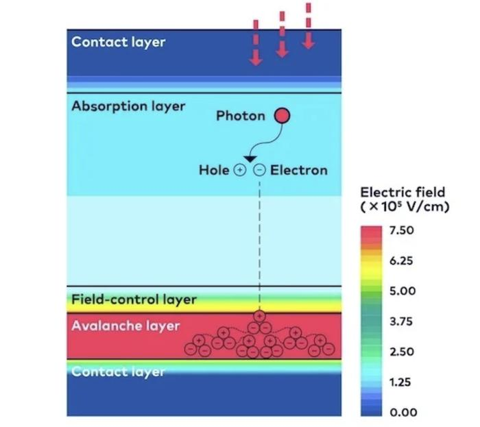
As with an ordinary photodiode, incident photons are absorbed in the absorption region, generating electron-hole pairs. The efficiency of this step is set by the quantum efficiency and is not essentially different from an ordinary PIN tube.
Impact Ionization and Avalanche Multiplication
The key to an APD is the multiplication region (also called the avalanche region). When a very high reverse bias (typically tens to hundreds of volts) is applied across the APD, the electric field in the multiplication region is extremely strong. Initial carriers (electrons or holes) are accelerated in this strong field, gaining high kinetic energy. When these energetic carriers strike lattice atoms, they can “knock” valence electrons out of the atoms, creating new electron-hole pairs — this is impact ionization. The newly generated carriers are again accelerated by the field and go on to strike and create more carriers. This process occurs in a chain reaction like an avalanche; a single initial carrier can ultimately generate hundreds or thousands of carriers, achieving internal current amplification. This amplification factor is called the multiplication factor (M).
Carrier Collection and Signal Output
The large number of multiplied carriers are collected by the electrodes, forming an output current far greater than the initial photocurrent. Thus the weak optical signal is amplified before entering the external electronic circuit, effectively reducing the impact of subsequent amplifier noise on overall signal-to-noise ratio.
APD Operating Mode Classification
APDs have two main operating modes: Linear mode: reverse bias below the breakdown voltage, with a finite multiplication factor (typically tens to hundreds), and output current proportional to incident optical power. This is the conventional mode for analog signal detection. Geiger mode: reverse bias slightly above the breakdown voltage, where a single-photon-triggered avalanche develops self-sustainingly, outputting a large current pulse. This mode is used for single-photon detection, with extremely high sensitivity, but the avalanche must be actively quenched after each detection before the next measurement.
III. Key Parameters: Understanding Performance Metrics
To understand APDs, knowing concepts and principles is not enough — you must also understand their key parameters. Many people, when selecting a laser, stare at a table of parameters without knowing where to start. There is no need to worry; the table below organises the core parameters clearly:
| Parameter | Meaning | Why It Matters |
|---|---|---|
| Multiplication Gain (M) | The avalanche amplification factor, i.e. the ratio of output photocurrent to initial photocurrent. APD gain is not fixed; it varies with reverse bias, temperature and incident wavelength. Typical gains range from tens to hundreds. | The APD’s core advantage, the internal current multiplication factor, from tens to hundreds. Gain raises weak-signal amplitude but also introduces excess noise, so there is an optimal gain point. |
| Responsivity | Output current per unit optical power. Thanks to internal gain, an APD’s responsivity can be tens to hundreds of times that of an ordinary PIN tube. | Measures how much photocurrent is produced per unit optical power, including the internal-gain contribution. Higher responsivity means a stronger output signal for the same input and lower demands on subsequent amplification. |
| Excess Noise Factor (F) | A parameter unique to APDs. The avalanche multiplication process itself introduces extra noise (because impact ionization is a random process), amplifying output noise more than input noise. The excess noise factor describes this “extra noise amplification”; smaller F is better. Silicon APDs have lower excess noise, InGaAs APDs relatively higher. | Measures the extra noise introduced by avalanche multiplication. The closer F is to 1, the lower the noise. Silicon APDs have lower excess noise than InGaAs APDs. |
| Breakdown Voltage | The reverse bias at which avalanche multiplication becomes self-sustaining. Geiger mode operates above breakdown, linear mode below. Breakdown voltage varies with temperature and needs compensation or control. | The reverse bias at which an APD undergoes avalanche breakdown, usually tens to hundreds of volts. The closer the operating bias to breakdown, the higher the gain but also the less stable. |
| Dark Current | The reverse current with no illumination. APD dark current is also amplified by the gain, so it affects APD performance more significantly than in ordinary PIN tubes. Dark current includes bulk dark current (multiplied) and surface leakage (unmultiplied). | The leakage current with no light, an important noise source. Lower dark current means better low-light detection and lower NEP. |
| Gain-Bandwidth Product | A comprehensive metric of APD high-speed performance. APD bandwidth decreases as gain rises, and the product of the two is a relatively stable value. A quality APD can have a gain-bandwidth product of tens to hundreds of GHz. | Determines the data rate and signal bandwidth an APD can support at high gain, a key metric for high-speed communication and rangefinding. A higher gain-bandwidth product means sufficient gain can be obtained while maintaining faster response. |
| Photoelectric Conversion Efficiency / Quantum Efficiency | The efficiency of initial carrier generation, defined the same as for an ordinary photodiode. Note that raising gain does not change quantum efficiency — it only amplifies carriers already generated. | Measures the fundamental efficiency of an APD at absorbing photons to generate photocarriers, directly affecting responsivity and signal-to-noise. Higher quantum efficiency means better low-light sensitivity. |
IV. Main Types: What Kinds of APDs Exist?
APDs can be classified in many ways; different dimensions help us understand their characteristics from different angles. The following introduces them by common classification approaches:
By Semiconductor Material
Silicon APDs (Si APD)
Mainly used from visible to near-IR (about 400–1100 nm). The electron and hole ionization rates in silicon differ greatly, giving a low excess noise factor (F can approach 2 or lower) and excellent performance. The first choice for visible and 800 nm band low-light detection.
InGaAs APDs
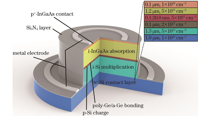
Mainly used in the 1310 nm and 1550 nm optical communication bands. InGaAs has higher excess noise than silicon, typically F around 3–5. A “separate absorption and multiplication” structure (SAM-APD) with InGaAs absorption region + InP multiplication region is usually used to optimise performance.
Germanium APDs (Ge APD)
Cover about 1000–1600 nm, relatively inexpensive, but with dark current and noise performance inferior to InGaAs APDs.
Other materials
Such as III-nitrides (UV detection) and HgCdTe (mid-IR), used for special wavelength bands.
By Structure and Operating Mode
Linear-mode APDs
Operate below breakdown voltage, outputting analog signals, used for continuous low-light detection.
Single-photon APDs (SPAD / Geiger-mode APD)
Operate above breakdown voltage, outputting in pulse form, able to detect single photons. Need a quenching circuit and have a dead-time limit.
APD arrays
Multiple APDs integrated on the same chip, used for position-sensitive detection or imaging applications.
By Package Type
Coaxial package
The most common low-cost package, with an optical window.
Fibre-coupled type
With a fibre pigtail for convenient connection to fibre systems, commonly used in optical communication.
Planar package / surface mount
Suited to high-density integration, such as optical communication transceiver modules.
Different APD types have their own strengths and weaknesses — there is no absolute “best,” only “most suitable.” Selection should consider your specific application, power needs, budget and other factors comprehensively. For example, industrial applications with high power requirements may favor fibre lasers; research applications needing ultrashort pulses may favor titanium-sapphire.
V. Applications: Where Are APDs Used?
APDs have a very broad range of applications, from industrial manufacturing to healthcare, from communication networks to scientific research — almost anywhere lasers are used, APDs are indispensable. A few fields are briefly described below:
- APDs are mainly used in low-light detection scenarios requiring high sensitivity:
- Long-distance fibre communication: in long-haul fibre transmission, the signal becomes very weak after attenuation over long fibre. APD receivers are several dB more sensitive than PIN receivers, extending transmission distance or reducing transmitter power requirements.
- Laser rangefinding and LiDAR: the reflected signal received in rangefinding is often very weak; APDs can effectively amplify the return signal, improving sensitivity and range. Autonomous-driving LiDAR, drone altimeters and other equipment widely use APD arrays.
- Single-photon detection: Geiger-mode APDs are among the most practical single-photon detectors, widely used in quantum key distribution (QKD), quantum optics experiments and fluorescence-lifetime imaging. Compared with superconducting detectors, they need no cryogenics, are compact and easy to use.
- Optical fibre sensing: in distributed temperature/strain sensing (DTS/DAS) and Brillouin optical time-domain reflectometry (BOTDR), backscattered signals are extremely weak and need highly sensitive APDs to detect.
- Biomedical detection: used in fluorescence detection, chemiluminescence detection, flow cytometry and other biomedical instruments to detect extremely weak fluorescence or luminescence signals.
- Radiation detection: in nuclear radiation detection, APDs can be paired with scintillators to detect gamma rays or X-rays.
- High-speed imaging: APD arrays can be used for low-light imaging such as night vision and astronomical observation.
🔧 Engineering selection tips
• Silicon APD vs. InGaAs APD: 800–1000 nm is best with silicon APDs (low noise, high gain); the 1310/1550 nm communication bands require InGaAs APDs, but with higher excess noise.
• Higher gain is not always better: beyond the optimal gain point, excess noise grows faster than signal gain and SNR actually falls. Every APD has an optimal operating gain.
• Temperature control is critical: APD breakdown voltage varies with temperature (about +0.2 V/°C for silicon); temperature swings cause gain drift, so precision measurement needs TEC temperature control or active bias compensation.
• Use a SPAD for single photons, not an ordinary APD: for single-photon counting, use a Geiger-mode SPAD operating above breakdown voltage, requiring a dedicated quenching circuit and outputting digital pulses rather than analog current.
VI. Common Misconceptions
Many people have plausible-sounding but wrong ideas about APDs. See if any of these misconceptions catch you out:
Misconception 1: The higher an APD’s gain, the better the signal-to-noise ratio
This is a common misconception. As APD gain rises, the signal is amplified — but so is the noise, and because of excess noise the noise grows faster than the signal. There is an optimal gain point where overall SNR is best. Beyond it, further increasing gain actually lowers SNR. In practice, gain is not the higher the better; the operating point must be chosen for the specific noise conditions.
Misconception 2: APDs are better than ordinary PIN tubes, so should be preferred
The APD’s advantage lies in low-light detection; when the optical signal is strong enough, an ordinary PIN tube actually has better SNR. Because APDs have excess noise, they degrade SNR under strong light. In addition, APDs need higher bias voltages (tens to hundreds of volts), more complex circuitry and higher cost. Using an APD is meaningful only when incident optical power is very low and preamplifier noise becomes the bottleneck.
Misconception 3: An APD’s gain is a fixed parameter
APD gain is not a fixed value; it is affected by several factors: higher reverse bias gives higher gain (rising very fast near breakdown); rising temperature lowers gain (because lattice scattering increases and ionization rates fall); incident wavelength also affects multiplication. In practice, temperature control or dynamic bias adjustment is needed to stabilize gain, otherwise gain drift affects measurement accuracy.
Misconception 4: A Geiger-mode APD can accurately measure the number of photons
An ordinary Geiger-mode APD can only answer “is there a photon?” (yes/no); it cannot distinguish whether 1 or 5 photons arrived — as long as one photon triggers the avalanche, the output pulse amplitude is the same. This is called “no photon-number resolution.” Only some special designs (such as arrays or special readout circuits) achieve limited photon-number resolution. True photon-number resolution requires other technologies such as superconducting detectors.
Leave a Reply