


Laser Focused Spot Size Calculator
Based on laser wavelength, lens focal length, incident beam diameter and M² (beam quality factor), calculate the Gaussian diffraction-limited spot, the Airy disc and the actual focused spot size taking aperture truncation into account
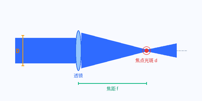
Focused Spot Size Calculator
Enter laser and lens parameters to calculate the Gaussian diffraction-limited spot, the Airy disc and the actual focused spot with aperture truncation
Linked with focal length / beam diameter
Fill in any two of focal length / beam diameter / f-number; M²=1 is the diffraction limit; a truncation ratio T of 0.7–0.9 is recommended in engineering (beam diameter about 70%–90% of the lens aperture)
Differences between the three spot sizes
Comparison of the Gaussian diffraction limit, Airy disc and actual focal spot
Focusing Principles Explained
Understand the effects of the diffraction limit, Airy disc, f-number and aperture truncation on the focused spot
Gaussian diffraction-limited spot
Diffraction Limit
The smallest spot to which an ideal aberration-free optical system can focus a Gaussian beam, determined by the wave nature of light. The 1/e² (intensity falling to 13.5% of the centre) diameter formula for a Gaussian beam is: d = 4λfM²/(πD) = 1.273·λ·f/#·M².
Airy disc
Airy Disc
The central bright spot formed in the focal plane when a uniform plane wave (flat-top beam) diffracts through a circular aperture. Its first dark ring diameter is: d_Airy = 2.44λf/D = 2.44λ·f/#, with about 83.8% of the energy concentrated in this bright spot.
f-number (aperture number)
f-number = f/D
The ratio of the lens focal length to the clear aperture (here taken as the beam diameter D). The smaller the f-number, the larger the relative aperture and the stronger the light-gathering ability, giving a smaller spot but also a shallower depth of focus.
Truncation ratio (aperture fill ratio)
Truncation Ratio, T = D_beam / D_aperture
The ratio of the 1/e² diameter of the incident beam at the lens to the lens clear aperture, consistent with the S/D convention used by manufacturers such as Thorlabs and Sill. The larger the T, the more the beam fills the aperture and the stronger the hard-edge truncation; the smaller the T, the finer the beam relative to the aperture and the weaker the truncation.
Practical Effects of the Truncation Ratio
The truncation ratio T is defined asbeam 1/e² diameter ÷ lens clear aperture. As T increases and the beam approaches or exceeds the aperture (T≥1), the beam is hard-edge truncated: ① the central focal spot grows markedly relative to the untruncated Gaussian spot (about 44% larger at T=1, with the spot coefficient rising from 1.273 to about 1.83λ·f/#); ② pronounced diffraction rings (sidelobes) appear; ③ the aperture power transmittance decreases.
Conversely, when T is very small (the beam much finer than the aperture), truncation is negligible and the spot approaches the untruncated Gaussian diffraction limit, but a larger-aperture lens is required. Practical optical systems generally use T≈0.7–0.9. The ‘actual focal spot (including M² and truncation)’ in this calculator is computed from the K(T) coefficient curve for focal-plane diffraction of a truncated Gaussian beam (K(T=1)≈1.83, derived from numerical calculation of Fraunhofer diffraction and consistent with the Thorlabs focusing optics tutorial).
Core Focused-Spot Formulas
Master these five formulas to quickly estimate focusing system parameters
Calculation Examples
Spot calculation examples for real laser focusing systems
Focused spot of a 1064 nm fibre laser marker
- f-number:f/# = 160/10 = f/16
- Gaussian diffraction-limited spot:d_diff = 4×1064×10⁻⁹×0.16/(π×0.01) ≈ 21.7 μm(M²=1)
- Actual Gaussian spot (including M²):d_real = 21.7×1.2 ≈ 26.0 μm
- Airy disc:d_Airy = 2.44×1064×10⁻⁹×0.16/0.01 ≈ 41.5 μm
- Depth of focus:DOF ≈ 2×1064×10⁻⁹×16²×1.2 ≈ 0.65 mm
Comparison of focusing capability: ultraviolet vs infrared lasers
- Infrared spot:d = 1.273×1064 nm×10×1.1 ≈ 14.9 μm
- Green spot:d = 1.273×532 nm×10×1.1 ≈ 7.5 μm(about 1/2 that of infrared)
- Ultraviolet spot:d = 1.273×355 nm×10×1.1 ≈ 5.0 μm(about 1/3 that of infrared)
- Conclusion:Spot diameter is proportional to wavelength. The 355 nm ultraviolet spot diameter is about 1/3 that of 1064 nm infrared, with a focused area of about 1/9 and a peak power density about 9 times higher — this is precisely why ultraviolet lasers suit precision micromachining.
Effects of each parameter on spot size
From d = 4λfM²/(πD) it follows that spot diameter is proportional to wavelength, focal length and M², and inversely proportional to beam diameter
Four ways to reduce the focused spot
Obtain a smaller, brighter focused spot in a real laser system
① Shorten the wavelength
Spot diameter is proportional to wavelength (d ∝ λ). Ultraviolet (355 nm) and green (532 nm) lasers give much smaller focused spots than infrared (1064 nm), but short-wavelength lasers and optics cost more.
② Reduce the focal length / f-number
Short-focal-length lenses give a smaller spot (d ∝ f), but the depth of focus shortens with f², placing greater demands on workpiece flatness, alignment and focusing accuracy; marking depth and process tolerance must be balanced.
③ Increase the incident beam diameter
Spot diameter is inversely proportional to beam diameter (d ∝ 1/D). First use abeam expanderto expand the beam before focusing, which can markedly shrink the focal spot and is the most common engineering approach (it requires a sufficiently large-aperturef-theta lens)。
④ Improve beam quality M²
Spot diameter is proportional to M². Replacing a multimode laser with a single-mode fibre laser (M²≈1), or optimising the optical path to reduce aberration and thermal lensing, can yield a spot closer to the diffraction limit. See alsoM² Beam Quality Factor Encyclopedia。
Common Questions about Focused Spots
How is the focused spot diameter calculated?
A Gaussian beam is defined by the 1/e² intensity level, giving a diffraction-limited spot diameter d = 4λf/(πD) = 1.273λ·f/#; the actual spot must additionally be multiplied by the beam quality factor M² and corrected by the K(T) coefficient for the aperture truncation ratio T. Enter the wavelength, focal length, beam diameter, M² and truncation ratio above to obtain the result directly.
What is the difference between the Airy disc and the Gaussian diffraction-limited spot?
The Airy disc applies to a uniform plane wave and is defined by the first dark ring, with diameter 2.44λf/D containing about 83.8% of the energy; the Gaussian diffraction-limited spot applies to a Gaussian beam and is defined by the 1/e² intensity level, with diameter 4λf/(πD) containing about 86.5% of the energy. For the same aperture and M²=1, the Gaussian 1/e² diameter is about 0.52 times the Airy disc first dark ring; the two use different criteria, so the same ‘diameter’ cannot be applied to both.
What is the f-number (f/#) and how does it affect the spot and depth of focus?
f-number = focal length ÷ clear aperture (f/D). Spot diameter is proportional to the f-number, while depth of focus is proportional to the square of the f-number: f/2 compared with f/10 gives a spot diameter of about 1/5 and a depth of focus of about 1/25. A small f-number focuses more finely but gives a shallower depth of focus and greater sensitivity to focusing.
How does M² (beam quality factor) affect the focal spot?
Actual focal spot diameter = diffraction-limited spot × M². Single-mode lasers have M² close to 1 and approach the diffraction limit; multimode lasers may have M² of 5–20 or even higher, enlarging the focal spot and reducing the energy density. Improving beam quality is one of the fundamental ways to shrink the focal spot.
What is the typical focal spot of a 1064 nm fibre marker?
Taking f=160 mm, beam diameter D=10 mm and M²=1.2 as an example: f/16, Gaussian diffraction limit about 21.7 μm, actual Gaussian spot including M² about 26.0 μm, Airy disc about 41.5 μm and depth of focus about 0.65 mm. Actual values vary with the f-theta lens focal length, expansion ratio and beam quality.
Why is the focused spot of an ultraviolet laser smaller than that of an infrared laser?
Because spot diameter is proportional to wavelength. At the same f/10 and M²=1.1, the 355 nm ultraviolet spot is about 5.0 μm and the 1064 nm infrared spot about 14.9 μm; the ultraviolet spot diameter is about 1/3 that of infrared, with about 1/9 the area and about 9 times the power density, making it better suited to precision micromachining.
What truncation (fill) ratio should be used — is smaller always better?
The truncation ratio T = beam 1/e² diameter ÷ lens aperture. A larger T means stronger truncation, a larger focal spot and more pronounced sidelobes (at T=1 only about 86.5% of the power passes and the spot grows by about 44%); too small a T gives almost no truncation but underuses the lens aperture and makes the equipment larger. In practice T≈0.7–0.9 is generally used (beam diameter about 70%–90% of the aperture), balancing spot quality, energy utilisation and lens cost. Note that this calculator uses the D_beam/D_aperture convention, the reverse of the ‘aperture/beam’ convention in some references, so confirm the definition before comparing values.
Related Optical Calculators and Encyclopedia
Companion Optical Calculators
Depth of Focus / Rayleigh Range Calculator
f-number and Numerical Aperture (NA) Calculator
Gaussian Beam Parameter Calculator
Optical Resolution Calculator
Related Optical Encyclopedia and Selection Guides
Laser Beam Expander Principles and Selection
F-theta Lens (Focusing Lens) Encyclopedia
M² Beam Quality Factor Encyclopedia
Laser Focusing Lens Encyclopedia