


What Is the Kerr Effect? How Light Intensity Changes the Refractive Index
The Kerr effect is the change in a medium’s refractive index under an electric field, proportional to the square of the field strength. Swap that applied field for light’s own and the index follows the intensity, Δn = n₂I. That is the optical Kerr effect, the common origin of self-phase modulation, cross-phase modulation and self-focusing, and the physical basis of supercontinuum generation, Kerr-lens mode locking and pulse compression. This article covers its three microscopic origins, six key parameters, four manifestations and six application areas.
Contents
- 1. What Is the Kerr Effect? The Core Concept
- 2. How It Works: Where the Kerr Effect Comes From
- 3. Key Parameters: Reading the Numbers Behind the Kerr Effect
- 4. Main Types: How the Kerr Effect Manifests
- 5. Applications: Where the Kerr Effect Is Actually Used
- 6. Common Misconceptions: Four Widely Held Myths
1. The Core Concept: What Is the Kerr Effect?
The Kerr effect is a change in the refractive index of a medium under an applied electric field, the change being proportional to the square of the field strength. It was the second electro-optic effect to be discovered, after the Pockels effect: the Pockels effect (Pockels effect) gives an index change linear in the field, whereas the Kerr effect gives one proportional to its square, which is why it is also called the quadratic electro-optic effect. That word “quadratic” describes the dependence on the field, not the nonlinear order — the two must be kept apart.
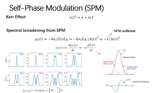
And when laser engineers and fibre-optic specialists speak of the Kerr effect today, they almost always mean the optical Kerr effect: what changes the refractive index is not an electrode but the light’s own field. The index change is then proportional to intensity, written Δn = n₂I, where n₂ is the nonlinear refractive index. This term arises from the third-order nonlinear susceptibility χ⁽³⁾ of the medium and belongs to the four-wave-mixing family, quite different in nature from second-order processes such as sum- and difference-frequency generation, which are governed by χ⁽²⁾. So the same phenomenon sits in two places in two classification schemes: by electro-optic effect it is a quadratic electro-optic effect; by nonlinear susceptibility it is a third-order nonlinear effect. Both statements are correct — they answer different questions.
Two types are distinguished. The electro-optic Kerr effect (DC Kerr effect) is produced by an applied DC or low-frequency field and makes an originally isotropic medium birefringent; the optical Kerr effect (AC Kerr effect) is produced by the light’s own strong field, changes the index with intensity and leaves the medium isotropic. The first makes devices, the second reshapes beams, and this article is about the second.
Almost every transparent medium shows an optical Kerr effect, but two conditions must be met before it is visible: the intensity must be high enough, and the interaction length long enough. Optical fibre satisfies both at once — a core only a few micrometres across gives very high power density at modest power, and runs of kilometres let the effect accumulate. That is why fused silica, with n₂ of only 2.6×10⁻²⁰ m²/W, supports strong enough Kerr nonlinearity in fibre to drive supercontinuum generation, passive mode locking and stimulated scattering. It also explains why fibre communications treat the Kerr effect as damage to be managed, while ultrafast optics treats it as the most useful tool available.
2. How It Works: Where the Kerr Effect Comes From
Three microscopic origins, three time scales
Kerr nonlinearity is not a single mechanism but a superposition of several, each on its own time scale. Knowing which ones and how fast is what tells you which model to use in a given experiment.
- Electronic distortion: the optical field pushes the bound electron cloud away from equilibrium, the polarisability changes and with it the refractive index. The response is sub-femtosecond to femtosecond, essentially instantaneous, and only weakly wavelength-dependent. This is the bulk of the “instantaneous Kerr” effect and the reason Kerr-lens mode locking can keep up with femtosecond pulses.
- Molecular orientation: polar molecules such as CS₂ or nitrobenzene rotate in the field, so a liquid that was isotropic becomes birefringent. The response is on the picosecond scale. The n₂ of CS₂ is about two orders of magnitude above that of silica, which is exactly why Kerr cells use it.
- Electrostriction: the spatial gradient of intensity squeezes the medium towards the bright regions, raising the local density and with it the refractive index. The response is on the nanosecond scale, negligible for femtosecond pulses but unavoidable for nanosecond pulses and continuous light.
All three add up to the measured n₂. This is also one reason why literature values for the same material differ slightly: measure with a different pulse duration and the weighting of the mechanisms changes.
From χ⁽³⁾ to n₂: how small the number is
In SI units n₂ is related to the real part of the third-order susceptibility by n₂ = 3Re[χ⁽³⁾]/(4ε₀cn₀²). The result is tiny: about 2.6×10⁻²⁰ m²/W for silica, which means that at an intensity of 10¹³ W/m² (10 GW/cm²) the refractive index changes by just 2.6×10⁻⁷. At that order of magnitude nothing is visible in isolation.
But phase does not care about a single point; it accumulates. From Δφ = (2π/λ)·Δn·L, an index change of 10⁻⁷ multiplied by a kilometre of fibre builds up several radians of phase shift — enough to broaden a spectrum visibly. The engineering significance of the Kerr effect never lies in how large Δn is, but in how far Δn can accumulate.
Why it is so strong in fibre: γ, not n₂
A fibre combines the material parameter and the waveguide geometry into one coefficient: γ = 2πn₂/(λA_eff), in rad/(W·m). A_eff is the effective mode area; the smaller it is, the higher the intensity at a given power and the larger γ becomes. Standard single-mode fibre has γ of about 1.3 /(W·km) at 1550 nm, while highly nonlinear fibre squeezes A_eff down to 1–2 μm² and reaches 10–20 /(W·km) — an order of magnitude more. What changed is not the material but the geometry.
The DC Kerr effect: why the Kerr cell gave way to the Pockels effect
With an applied field, Δn = λKE², where K is the Kerr constant. The medium then presents different refractive indices to light polarised parallel and perpendicular to the field, producing induced birefringence. A Kerr cell (Kerr cell) is a cell with electrodes at both ends filled with a polar liquid such as nitrobenzene; voltage controls the polarisation state, giving a fast optical shutter or modulator.
Its shortcomings are concrete: Δn scales with E², so reaching a usable phase difference calls for kilovolt drives, and nitrobenzene is toxic. Apart from cases that genuinely need picosecond response, such as ultra-high-speed photography, practical electro-optic modulators therefore use Pockels-effect crystals (LiNbO₃, KDP) instead, because Δn scales with E and the drive voltage drops by more than an order of magnitude.
A one-line way to remember it: the Pockels effect goes with the first power of the field, the Kerr effect with its square — so for the same Δn the Kerr effect needs a far larger field; and the optical Kerr effect replaces “applied field” with “the light’s own field”, which turns it into a first power of intensity and makes it very easy to reach in fibre.
3. Key Parameters: Reading the Numbers Behind the Kerr Effect
There is usually no datasheet to read for the Kerr effect, because most of the time it is a property of the material and a constraint on the system rather than a box you buy. These six quantities are the ones to pin down when designing or evaluating:
| Parameter | Meaning | Why it matters |
|---|---|---|
| Nonlinear refractive index n₂ | The basic parameter for the strength of the optical Kerr effect, that is, the rate at which the index changes with intensity, n = n₀ + n₂I, in m²/W. About 2.6×10⁻²⁰ m²/W for silica. | It is the physical origin of every Kerr-type nonlinear effect (SPM, XPM, self-focusing and so on). The larger n₂, the more the index moves at a given intensity. When choosing a nonlinear material, n₂ is the first number to look at. |
| Nonlinear coefficient γ | The parameter that expresses Kerr nonlinearity in a fibre, γ = 2πn₂/(λA_eff), in rad/(W·m). It folds material properties and waveguide geometry together. | It is the central parameter of fibre nonlinear design. The larger γ, the more nonlinear phase shift per unit power and unit length, and the more readily SPM and stimulated scattering occur. Highly nonlinear fibre raises γ precisely by shrinking the mode area. |
| Nonlinear length L_NL | Defined as L_NL = 1/(γP₀): the length over which a pulse of peak power P₀ accumulates one radian of peak nonlinear phase shift. | It is the characteristic scale over which nonlinearity accumulates. When L_NL is far shorter than the actual length the effect is significant; when far longer it can be ignored. Deciding whether a system needs a nonlinear treatment means comparing these two lengths. |
| Kerr response time | The time a medium needs to develop a nonlinear polarisation response to a change in the optical field. The electronic contribution is very fast (about 10⁻¹⁵ s), molecular orientation is slower (about 10⁻¹² s) and electrostriction slower still (nanoseconds). | It decides whether the Kerr effect can follow the field. For femtosecond pulses only the electronic response keeps up; molecular and electrostrictive responses lag and directly affect how ultrashort pulses propagate nonlinearly. |
| Critical power for self-focusing P_cr | The power above which Kerr self-focusing overcomes diffraction, so the beam collapses and may form filaments. Of order P_cr ≈ λ²/(2πn₀n₂). | It sets the maximum peak power a medium can carry. Beyond the threshold the beam self-focuses, the local intensity spikes and the material is damaged, which is a major limit on high-power laser systems. In fibre the waveguide confines the beam, so the limit shows up mainly as end-face damage. |
| Third-order nonlinear susceptibility χ⁽³⁾ | The macroscopic tensor describing the strength of a medium’s third-order nonlinear response, directly related to n₂. The Kerr effect is one of its most direct manifestations. | It is the fundamental physical quantity of a material’s nonlinear optical behaviour. The larger χ⁽³⁾, the stronger the Kerr effect, third-harmonic generation and four-wave mixing all become. Values for different materials can differ by several orders of magnitude. |
4. Main Types: How the Kerr Effect Manifests
Once the intensity is high enough to move the refractive index, the Kerr effect appears in a few distinguishable forms. There are two threads to sort them by: whether it acts in time or in space, and how fast it responds. The first decides what the phenomenon looks like; the second decides whether it can be used on ultrafast processes.
By manifestation
- Self-phase modulation (SPM): the temporal intensity envelope of a single beam changes its own phase. The leading and trailing edges see different instantaneous refractive indices, so the pulse leaves carrying a time-varying phase and its spectrum broadens. This is the first step of supercontinuum generation and the prerequisite for pulse compression.
- Cross-phase modulation (XPM): when two or more beams travel together, the intensity of one modulates the phase of another. In wavelength-division-multiplexed systems this is a real source of crosstalk — power fluctuations in one channel are transferred onto its neighbours and upset the balance.
- Self-focusing (Kerr lens): the transverse intensity profile creates a transverse index profile, high in the centre and low at the edges, which acts as a positive lens. Above the critical power self-focusing beats diffraction, the beam collapses and, given the right conditions, forms filaments; given the wrong ones, it damages the material.
- Self-steepening: the index changes fastest at the pulse peak, so the group velocity changes with it, the trailing edge catches up with the leading edge and the pulse becomes asymmetric with a steepened front. At femtosecond durations this term has to be included, or the group-velocity dispersion to be compensated will be misestimated.
By response time
- Electronic Kerr effect: arises from distortion of the electron cloud, responds in sub-femtosecond to femtosecond time and dominates the instantaneous Kerr effect. Femtosecond nonlinear processes recognise essentially nothing else.
- Orientational Kerr effect: arises from the rotation of polar molecules, responds on the picosecond scale, is especially pronounced in liquids such as CS₂ and nitrobenzene, and is the physical basis of Kerr-cell media.
- Electrostrictive Kerr effect: arises from the density change driven by the optical field, responds on the nanosecond scale, can be neglected for short pulses and must be included for long pulses and continuous light.
Those three time scales decide which model to use: an instantaneous model for femtosecond pulses, a model with relaxation for nanosecond pulses, and caution in between — that intermediate range is exactly where the “approximately instantaneous” assumption fails most easily.
5. Applications: Where the Kerr Effect Is Actually Used
All six areas share one criterion: the need to control light with light, at a speed no other mechanism can match.
- Passive mode locking (Kerr-lens mode locking): a Kerr lens combined with a hard aperture in the cavity forms an equivalent saturable absorber — a pulse of high peak power self-focuses and passes the aperture almost completely, while weak light is blocked, so the stronger the pulse the lower the loss, and passive mode locking establishes itself. Titanium-sapphire femtosecond lasers are the classic example, and this was the step that turned femtosecond technology from a laboratory curiosity into a commercial product in the 1990s.
- Supercontinuum generation: in highly nonlinear or photonic-crystal fibre, SPM broadens the spectrum first, then soliton fission, four-wave mixing and stimulated Raman scattering take over, and the result can span more than an octave to form “white light”. Spectroscopy, optical frequency combs and OCT imaging all rely on it for a broadband source.
- Pulse compression: SPM imposes a positive chirp (frequency rising with time), which a negative-dispersion element (grating pair, prism pair, chirped mirrors) then cancels, shortening the pulse. This is the basic principle of nonlinear pulse compression and the standard route to few-cycle pulses.
- Optical switching and all-optical signal processing: the intensity of a control beam shifts the phase of a signal beam, and an interferometric structure converts that into an amplitude change, giving all-optical switching, wavelength conversion and regeneration. The speed advantage is obvious — no carrier lifetime sets the limit, so the response can reach the femtosecond range.
- Kerr-cell high-speed photography: the classic application of the electro-optic Kerr effect. A Kerr cell serves as an ultra-fast shutter with a gate time down to nanoseconds or less, recording explosions, discharges and shock waves. It has largely been displaced by ICCD cameras and ultrafast framing cameras, yet it remains hard to replace where strong electromagnetic interference is present.
- Nonlinear pulse shaping: by designing the combination of nonlinear medium and dispersive elements so that SPM and dispersion cancel or reinforce each other at chosen points, pulses of a specific shape can be produced — parabolic or flat-top, for instance — for particular laser-processing and particle-acceleration tasks.
6. Common Misconceptions: Four Widely Held Myths
The Kerr effect comes down to a single line, Δn = n₂I, and the misunderstandings cluster around mistaking that line for the whole story.
Misconception 1: The Kerr effect is self-phase modulation, the two are the same thing
They are not. The Kerr effect is the physical phenomenon — the refractive index changing with intensity; self-phase modulation is one consequence of it, in a single beam and along the time axis. The same Kerr effect also appears as self-focusing in space, as cross-phase modulation between beams and as self-steepening of a pulse. Mistaking SPM for the Kerr effect itself is the surest way to overlook self-focusing — and in high-power systems self-focusing is the more dangerous of the two.
Misconception 2: The nonlinear refractive index n₂ is always positive
Not necessarily. Most transparent media far from an absorption band have positive n₂ and self-focus, but when the photon energy approaches the bandgap (around seventy per cent and above) n₂ can turn negative and the beam self-defocuses. Semiconductors near the band edge are the classic case. The sign decides whether a high-power beam collapses or spreads, and it must be confirmed before designing a high-power device.
Misconception 3: The optical Kerr response is completely instantaneous
Approximately true, strictly false. The electronic response really is near-instantaneous (femtosecond), but molecular orientation (picosecond) and electrostriction (nanosecond) both lag. For femtosecond and picosecond pulses the latter two can be dropped; for nanosecond pulses they cannot. Much of the discrepancy between published n₂ values for the same material comes down to different measurement pulse durations and therefore different weightings of the mechanisms.
Misconception 4: The stronger the Kerr effect of a material, the better
Not necessarily. Supercontinuum generation and Kerr-lens mode locking genuinely want a large n₂, but high-power transmission and fibre communications want the opposite — strong nonlinearity brings spectral broadening, channel crosstalk and pulse distortion, and in the worst case end-face damage. Engineering therefore often sets out to reduce nonlinearity: use large-mode-area fibre, move to a longer wavelength, or spread the power over a larger area. Choosing a material is a trade-off, not a contest of magnitudes.
Leave a Reply