


An aperture stop is the component in an optical system that specifically manages the ‘size of the opening’. Open the aperture too wide and stray light, reflections from the barrel walls and large-angle scattered light all pour in, creating noise and hot spots; close it too far and edge clipping causes diffraction rings, power loss and even return-light feedback. This article explains the stop’s role in optical design, the mechanical principle of the iris diaphragm, the safety lines in laser paths and the selection method, with specifications you can order directly.
1. Definition of Terms and Basic Concepts
An aperture stop (stop) is an opening that limits the aperture through which a beam passes in an optical system. The term has two meanings in engineering: at the optical-design level, it is the aperture surface that limits the beam — including the aperture stop, field stop and vignetting stop — an abstract surface in design theory; at the physical-component level, it is a mountable, adjustable mechanical opening — the variable iris diaphragm and fixed stop disc, the subject of this article.
Stops come in two main physical forms:
| Form | Structural feature | Typical application |
|---|---|---|
| Variable iris diaphragm | Overlapping thin metal blades forming a near-polygonal opening, driven by a lever or rotating ring, with continuously adjustable aperture | Laser experiment paths, microscope illumination, built-in camera apertures |
| Fixed aperture (stop disc) | A single precision-drilled metal plate, fixed aperture, high centring accuracy, low cost | Situations where the aperture is fixed (blocking stray light before a sensor, production equipment) |
Related terms distinguished — several easily confused opening/light-blocking components:
| Term | Relationship to a stop |
|---|---|
| Camera lens aperture | Essentially the same mechanism as an iris diaphragm, only integrated inside a lens group with f-number markings; a standalone iris is used in free-space optical paths |
| Pinhole | A fixed micro-hole of micrometre scale (1–100 μm) mounted in a precision holder for spatial filtering, turning a focused spot into a clean spherical wave — not an iris diaphragm |
| Slit | An elongated opening used in spectrometers/monochromators to control resolution and throughput |
| Beam dump | Its function is to absorb the entire beam energy, not to limit an aperture — a completely different use |
The opening of an iris diaphragm is enclosed by n overlapping blades, commonly 5–25, with 10–14 typical in laser and industrial use. The more blades, the rounder the opening: nearly circular when fully open, a regular n-gon when stopped down. The straight edges of a polygon produce diffraction spikes, one of the factors to weigh when choosing the blade count.
2. Working Principle
2.1 The role of the stop in an optical system (design level)
The aperture stop is the opening that limits the solid angle of the imaging beam from an on-axis object point; it determines the system’s numerical aperture (NA) and f-number:
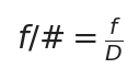
f is the system focal length and D the entrance-pupil diameter; the f-number is the standard way an imaging system describes the stop’s relative light-passing ability, a smaller f-number meaning a relatively larger aperture
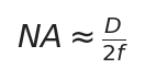
In the paraxial approximation in air, NA is the numerical aperture; NA and f-number describe the same fact: the larger the aperture, the larger the cone angle of light the system gathers
The aperture stop directly controls two quantities. One is light throughput — the luminous flux through the stop is proportional to the clear area:
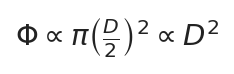
Flux through the stop is proportional to clear area, i.e. to the square of the aperture diameter; doubling the aperture quadruples the throughput
The other is diffraction-limited resolution. An ideal circular aperture images a point object as an Airy disk, whose diameter is:

λ is the wavelength; the diameter of the Airy disk’s first dark ring sets the diffraction-limited resolution; a smaller aperture D gives a larger Airy disk and lower limiting resolution
Thus ‘the smaller the aperture, the higher the resolution’ is a common misconception: stopping down mainly increases depth of field; once the aperture is small enough for diffraction to dominate, the Airy disk grows and resolution actually falls. The real benefit of a small aperture is depth of field, not resolution.
The field stop limits the imaging extent (field size) and lies in a plane conjugate to the object or image plane, a different role from the aperture stop. Vignetting is the partial obstruction of off-axis beams by the edges of several openings in the system, darkening the field edge; how well the stop aperture matches the lens-group apertures sets the degree of vignetting. Depth of field correlates with f-number: a larger f-number (smaller aperture) gives greater depth of field — the physical basis for stopping down the aperture stop in microscopy and machine vision to gain depth of field, but resolution loss and diffraction blur must be accepted at the same time.
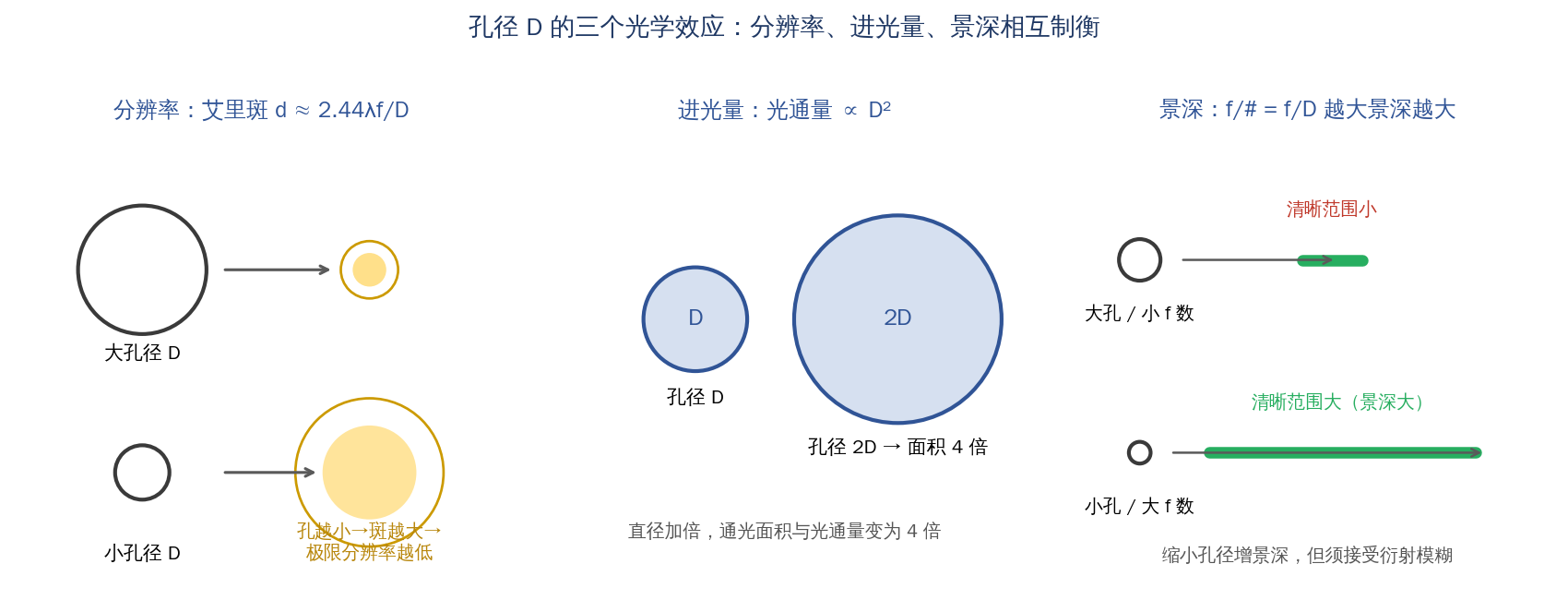
The three optical effects of aperture D: Airy disk (resolution), light throughput and depth of field balance one another
Source: drawn by the Soar Laser technical team
2.2 Mechanical principle of the iris diaphragm (component level)
An iris diaphragm is a purely mechanical synchronised linkage, containing no lens and no optical surface. Each blade is pinned at one end to a fixed ring, with the other end seated in a slot in a rotating ring; as the ring turns, all blades swing in unison and the overlapping opening scales continuously.
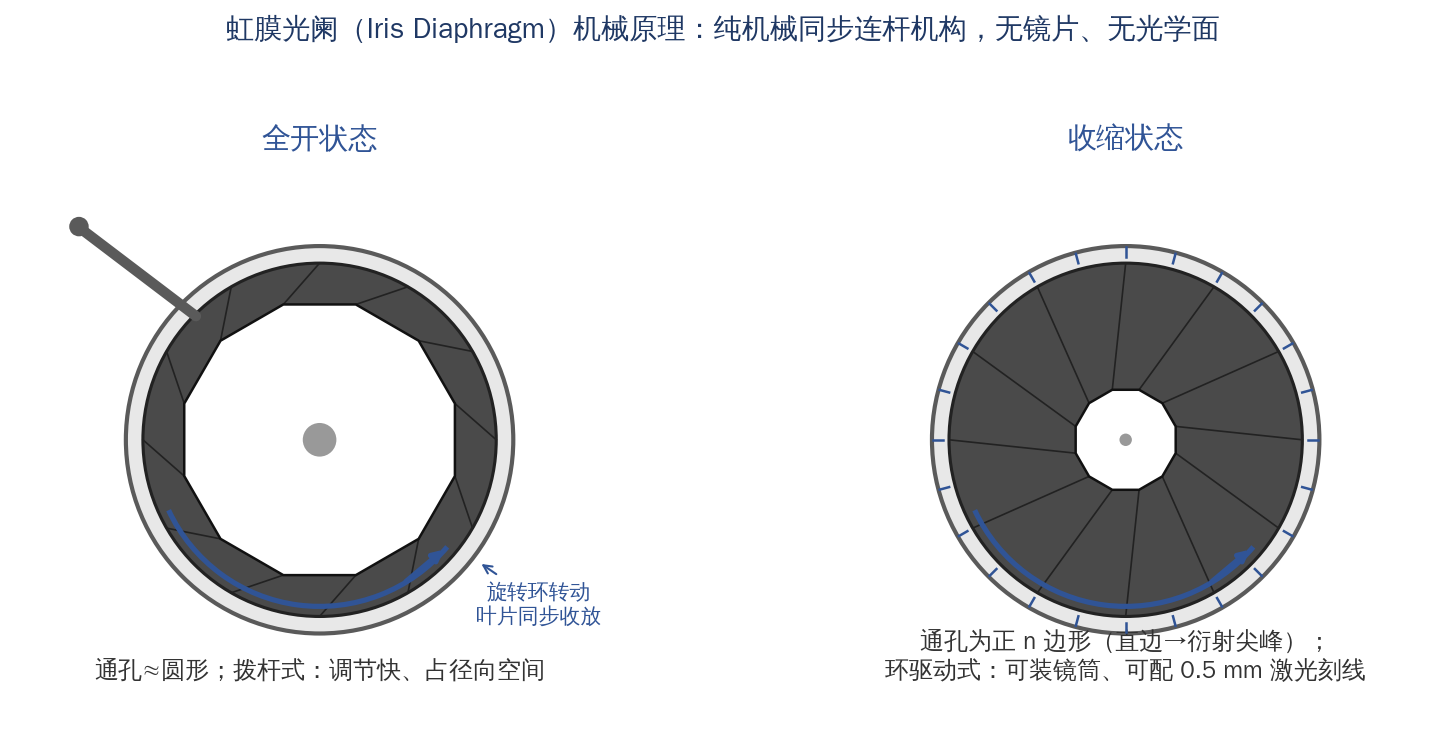
Iris diaphragm mechanical principle: the rotating ring drives the blades to open and close in unison, lever-actuated versus ring-actuated compared
Source: drawn by the Soar Laser technical team
On opening shape and blade count: n blades enclose an almost circular n-gon. More blades give better roundness (reducing diffraction spikes from polygonal straight edges), but also more reflective blade edges, a larger minimum achievable aperture and a more complex mechanism. Laser paths commonly use 10–14 blades as the balance point.
Minimum-aperture limit: constrained by blade-tip geometry, an iris cannot close to zero. Typical commercial minimum apertures are 0.5–2.5 mm, and ‘minimum aperture’ is a parameter that must be checked when selecting. Taking Thorlabs standard-thread irises as an example: an SM1-interface standard type has a minimum aperture of about Ø0.8 mm, SM2 about Ø1.4 mm and the large-aperture SM3 about Ø2.5 mm. When sub-millimetre or micrometre apertures are needed, choose a pinhole rather than an iris; for complete light blocking use a shutter or a zero-aperture stop.
Two actuation methods: the lever-actuated type is pushed and pulled directly by a side lever, adjusting quickly but taking radial space and being easy to knock — suited to temporary adjustment of free-space paths; the ring-actuated type turns an outer graduated ring, can be fitted inside a threaded tube, is axially compact and repeatable — suited to permanent mounting in a lens barrel or lens tube. Ring-actuated types can also carry laser-engraved graduations (e.g. a mark every 0.5 mm) for repeatedly returning to the same aperture.
2.3 The special role of stops in laser paths and the safety lines
In a laser path a stop has three legitimate uses:
① Beam-diameter matching. Beams from beam expanders and collimators are usually specified by their 1/e² diameter, but a fundamental-mode Gaussian beam still carries energy outside the 1/e² boundary:
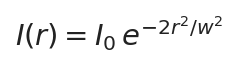
A fundamental Gaussian beam’s intensity decays radially by a Gaussian profile, with beam radius w defined at the 1/e² intensity point; about 13.5% of total power still lies outside this boundary, which is the direct reason the iris opening must be noticeably larger than the beam and must not clip its edge
The iris opening should therefore be clearly larger than the beam, typically leaving 1.5–2 times or more margin (allowing for alignment error, beam divergence and thermal drift), to ‘block’ the beam boundary and prevent large-diameter stray light from reaching downstream small-aperture components.
② Stray-light and ghost-beam management. Scattered light, end-face reflection ghosts and pump leakage in a laser path travel in disorderly directions; placing a stop before critical lens groups blocks off-axis stray light, improves signal-to-noise ratio and prevents stray light from reflecting repeatedly off the barrel wall into hot spots.
③ Beam-size observation and coarse adjustment in low-power alignment or alignment-beam paths.
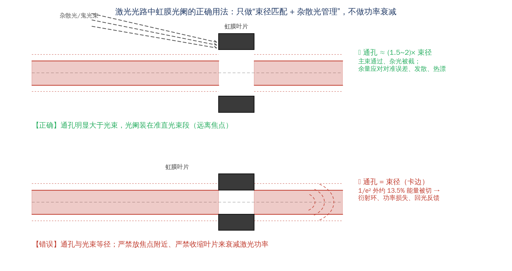
Correct use of an iris in a laser path: leave 1.5–2 times beam-diameter margin in the opening and mount it in the collimated section; an equal-diameter edge clips the beam, producing diffraction and return light
Source: drawn by the Soar Laser technical team
⚠ Safety line one: an iris must never be used to adjust laser power. The blades are metal (spring steel or blackened stainless steel); when the aperture is closed, the blocked portion of laser power is absorbed by the blades or mirror-reflected from their edges, with three consequences: ① at high power the blades rapidly heat, deform, anneal and burn through; ② reflection from blade edges is uncontrollable and may return to the laser as feedback or strike other optics; ③ the blade mechanism seizes after heating. Continuously adjustable laser attenuation must use a half-wave plate + polarising beam-splitter/Glan prism combination, power-rated neutral-density filters (ND filters), or a dedicated laser attenuator. The stop handles ‘aperture’ only, never ‘power’.
⚠ Safety line two: do not place a stop near a focus. Power density is highest at the focus; even if the opening exceeds the focal spot, stray diffracted light can readily damage the blade edges. Where a small aperture is needed for limiting, put it in the collimated-beam section; where filtering at the focus is required, use a microscope objective + pinhole spatial-filter arrangement.
3. Structure and Classification
A typical iris diaphragm consists of inner and outer metal rings + the blade set + pins/slots + the actuator (lever or graduated ring) + the mounting interface. The blades are blackened spring steel/stainless steel (low reflection) and the housing is black-anodised aluminium alloy. Classification dimensions are as follows:
| Classification dimension | Type | Feature |
|---|---|---|
| Adjustability | Variable iris / fixed stop disc | Continuously adjustable versus single aperture, high centring accuracy, no mechanical play, lowest cost |
| Actuation | Lever / ring actuated | Lever is fast but takes space and is easy to knock; ring-actuated is compact, can be graduated and is repeatable |
| Mounting interface | Threaded tube / C-Mount / bare (with a stop holder) / cage / large aperture | Threaded types screw directly into lens tubes and barrels |
| Aperture range | Micro (max about 5 mm) / standard (about 12–25 mm) / large aperture (over 50 mm) | SM1/SM2 standard types are most common in laser experiments |
Standard microscope thread sizes (most used in laser paths, not mutually compatible): SM05 = 0.535″-40, SM1 = 1.035″-40, SM2 = 2.035″-40, SM3 = 3.035″-40. When selecting, the thread must match the existing lens tube/barrel; a wrong purchase will not fit.
Pinholes and spatial-filter assemblies: a pinhole (1–100 μm class) is mounted at a microscope objective’s focus for spatial filtering, as a ‘fixed micro-hole + precision three-axis stage’ combination — structurally not an iris.
| Component | Aperture range | Adjustability | Typical use | Can it adjust laser power? |
|---|---|---|---|---|
| Iris diaphragm | Min about 0.5–2.5 mm up to max 5–50+ mm | Continuously adjustable | Beam-size matching, blocking stray light, illumination dimming | ❌ Strictly forbidden |
| Fixed stop disc | Customisable (μm–mm) | Not adjustable | Fixed-aperture stray-light blocking | ❌ Strictly forbidden |
| Pinhole | 1~100 μm | Not adjustable (three-axis alignment) | Spatial filtering | ❌ Strictly forbidden |
| Slit | Slit width μm–mm class | Partly adjustable | Spectrometer resolution / throughput | ❌ Strictly forbidden |
| Beam dump | No opening | — | Absorbs the whole beam | (not an aperture-limiting component) |
4. Key Parameters
| Parameter | Meaning and typical value | Selection significance |
|---|---|---|
| Min/max clear aperture | Max aperture sets the largest beam that can pass; min aperture sets the adjustment limit, and an iris cannot reach 0 (typically 0.5–2.5 mm) | The opening must be larger than the beam with 1.5–2 times margin |
| Blade count | Typically 5–25, with 10–14 common in laser/industrial use | Affects opening roundness (diffraction spikes) and minimum aperture |
| Actuation | Lever / ring actuated | Sets mounting method, space used and repeatability |
| Mounting interface | SM05/SM1/SM2/SM3, C-Mount, cage, etc. | Must match the existing barrel/tube; threads are not mutually compatible |
| Opening centring accuracy / coaxiality | Fixed stops and ring-actuated types centre well; lever types may go off-centre when adjusted | Affects beam coaxiality with the system optical axis |
| Adjustment repeatability and graduations | Ring-actuated types can have laser engraving (e.g. every 0.5 mm) | For applications repeatedly returning to one aperture, choose a graduated ring-actuated type |
| Material and surface treatment | Blades blackened, housing black-anodised | Low reflection, absorbs stray light; bright blades create ghost light |
| Applicable power and wavelength | Essentially a metal mechanical part, uncoated, with no quoted optical damage threshold | Only for low/medium-power collimated sections where the beam never touches the blades; at high power keep well away from focus with ample aperture margin |
| Operating temperature and thermal stability | Blade deformation from heat can seize the mechanism | Use with caution in high-power environments; choose a fixed stop disc where needed |
5. Characteristics: Pros and Cons
Variable iris diaphragm: the advantage is a continuously adjustable aperture — one component suits many beam sizes and experimental conditions and can be adjusted dynamically while the system runs; limits are a finite minimum aperture (nothing below sub-millimetre), diffraction spikes from polygonal openings, centring error from mechanical play, lever types being easy to knock, inability to withstand the beam sweeping the blades, and lifetime concerns from moving parts.
Fixed stop disc: advantages are high centring accuracy, no play, very low cost, high reliability with no moving parts and any aperture customisable; the limit is that changing aperture means changing the part, with no dynamic adjustment.
Pinhole: a micrometre-scale aperture for spatial filtering, giving a clean Gaussian beam; but easily blocked by dust, requiring a precision three-axis alignment stage and sensitive to vibration.
| Characteristic | Variable iris | Fixed stop disc | Pinhole |
|---|---|---|---|
| Aperture range | About 0.5–50 mm | Any custom value | 1~100 μm |
| Adjustability | Continuously adjustable | Not adjustable (change part) | Not adjustable (three-axis alignment) |
| Centring accuracy | Medium (lever type risks eccentricity) | High | High (with a three-axis stage) |
| Cost | Medium | Very low | High (including stage) |
| Reliability | Has moving parts | No moving parts, highest | Easily blocked, vibration-sensitive |
| Typical application | Lab-path beam matching, illumination | Fixed aperture in production equipment | Laser spatial filtering |
6. Typical Applications and Selection Guidance
Typical applications:
- Laser-path beam-size matching: add an SM1/SM2 iris after a beam expander/collimator, set the opening to 1.5–2 times the beam diameter to bound stray light — continuously adjustable, adapting to different beam sizes.
- Microscope illumination and machine vision: the condenser iris adjusts illumination NA to match the objective NA for the best contrast/depth-of-field balance; a built-in lens aperture sets the f-number.
- Spectrometer / monochromator: a slit controls resolution and throughput.
- Spatial filtering: a microscope objective + pinhole removes high-frequency laser noise for a clean Gaussian beam.
- Illumination / projection systems: a large-aperture iris adjusts the illuminated extent.
- Positions with a fixed aperture in production equipment: use a fixed stop disc (stray-light blocking before a sensor, fixed-f-number systems), at the lowest cost and highest reliability.
Selection decision tree:
- What is the use? Need to change aperture continuously → iris; fixed aperture → fixed stop disc (cheaper and more reliable); micrometre-scale filtering → pinhole.
- How powerful is the laser, and will the beam sweep the stop? Only if the beam never touches the blades (1.5–2 times aperture margin) may a stop be used in a laser path; to adjust power by blocking blades instead → choose a half-wave plate + polarising splitter combination or an ND attenuator; a stop is never acceptable.
- Where will it be mounted? Screwed into a lens tube/barrel → ring-actuated type + the matching thread (choose SM1/SM2/SM3 by beam diameter); temporary free-space adjustment → lever type + a stop holder.
- Sensitive to opening roundness? For diffraction/imaging sensitivity → choose a higher blade count; for coarse stray-light blocking → a standard blade count is fine.
- Will it sit near a focus? If yes → move it to the collimated section, or switch to pinhole filtering at the focus.
Selection / use examples:
- Example one: in a path with an 8 mm beam after a beam expander, the opening needs 1.5–2 times margin, i.e. a maximum aperture of at least 12–16 mm. An SM1 interface (max Ø12 mm) already clips the beam, so choose an SM2 interface (max Ø25 mm) iris, which also leaves ample adjustment range at the lower end; never force an SM1 iris with a 12 mm maximum to clip the edge.
- Example two: you cannot ‘dial’ a 50 W laser down to half power with an iris. The roughly 25 W absorbed by the blocked blades will burn them through within seconds, and uncontrolled edge reflections may feed back. The correct approach is a half-wave plate + polarising beam-splitter combination, or a power-rated high-power ND attenuator; keep the stop only for beam-size matching.
- Example three: when a microscopy vision station lacks depth of field, stop down the condenser iris (reduce illumination NA, increase effective f-number) to increase depth of field, but use a resolution target to confirm diffraction blur has not exceeded the inspection requirement, balancing contrast, depth of field and resolution.
7. Common Misconceptions and Pitfalls
| Common misconception | Correct understanding / consequence |
|---|---|
| Using an iris contraction to adjust laser power | Blade absorption heats and burns through, with uncontrollable reflective feedback, damaging within seconds at high power; attenuate power with a waveplate + polarising element or an ND filter |
| Believing ‘the smaller the aperture, the higher the resolution’ | A photographic rule misapplied: once the aperture reaches the diffraction limit the Airy disk grows (2.44λf/D) and resolution falls; the real benefit of a small aperture is depth of field |
| Setting the opening diameter exactly equal to the laser beam diameter | About 13.5% of power outside the 1/e² edge + alignment error + thermal drift inevitably clips the beam, causing diffraction rings, power loss and return light; leave at least 1.5–2 times margin |
| Placing a stop near a focus | Power density is highest at the focus and stray diffracted light burns the blades; move it to the collimated-beam section |
| Confusing an iris with a pinhole | A pinhole is a micrometre-scale fixed hole for spatial filtering; an iris has a minimum aperture only down to sub-millimetre/2.5 mm and a polygonal opening |
| Thinking an iris can close fully to zero | Blade geometry sets a lower limit on minimum aperture; for full blocking use a shutter or a zero-aperture stop |
| Looking only at maximum aperture, ignoring the interface | SM05/SM1/SM2/SM3 threads are not mutually compatible — a wrong purchase will not fit |
| Ignoring the radial space and knock risk of lever types | For mounting inside a closed barrel, a ring-actuated type is mandatory |
| Thinking more blades are always better | Roundness improves, but reflective blade edges increase, minimum aperture grows and the mechanism gets more complex; 10–14 is the common balance |
| Applying the photographic f-number concept to a free-space laser path | Laser beam diameter is set by the expansion ratio; f/# applies only to imaging/focusing systems |
| Ignoring the purpose of the blackened finish | Bright blades reflect stray light into new ghost sources; choose blackened blades / a black-anodised housing |
| Using plastic parts or ordinary non-blackened stops in high-power equipment | Laser environments require blackened metal parts, kept well away from the beam sweep path |
8. References and Further Reading
- RP Photonics Encyclopedia, Optical Apertures (Optical Apertures entry), https://www.rp-photonics.com/optical_apertures.html
- RP Photonics Encyclopedia, Aperture Stops (aperture stop, entrance/exit pupil entry), https://www.rp-photonics.com/aperture_stops.html
- RP Photonics Encyclopedia, Diaphragms (variable diaphragm / iris entry), https://www.rp-photonics.com/diaphragms.html
- RP Photonics Encyclopedia, Numerical Aperture (Numerical Aperture entry), https://www.rp-photonics.com/numerical_aperture.html
- RP Photonics Encyclopedia, Pinholes (pinhole and spatial filtering entry), https://www.rp-photonics.com/pinholes.html
- RP Photonics Encyclopedia, F-number (F-number entry), https://www.rp-photonics.com/f_number.html
- Thorlabs, Iris Diaphragms (iris products and selection guide, including SM05/SM1/SM2/SM3 specifications), https://www.thorlabs.com/newgrouppage9.cfm?objectgroup_id=1464
- Edmund Optics, Apertures, Pinholes & Slits (aperture, pinhole and slit product literature), https://www.edmundoptics.com/c/apertures-slits/
- Newport / MKS Instruments, Optical Mounts & Hardware (optomechanical product literature), https://www.newport.com/f/optical-mounts
- ZEISS Microscopy, Microscopy Basics (technical documentation on microscope aperture stops and condenser NA matching, ZEISS Campus), https://zeiss-campus.magnet.fsu.edu/
- W. J. Smith, Modern Optical Engineering: The Design of Optical Systems, 4th ed., McGraw-Hill, 2007 (chapters on stops, apertures and vignetting)
- J. E. Greivenkamp, Field Guide to Geometrical Optics, SPIE Press, 2004 (Airy disk and diffraction-limited resolution entries)
Soar Laser · Laser Optics Knowledge Base | Hotline 15927220467 | This article is technical education; refer to product-page parameters for specific specifications
Leave a Reply