


1. Definition of Terms
An achromatic field lens (Achromatic F-Theta Lens, also called an achromatic scanning lens, dual-wavelength field lens or multi-wavelength F-Theta lens) is a special flat-field focusing lens used in galvo scanning systems. On top of the ‘flat focus, linear scan’ behaviour of an ordinary F-Theta lens, it corrects chromatic aberration for two or more specified wavelengths simultaneously, so beams of different wavelengths focus on the same focal plane, while keeping the scan field size consistent across wavelengths and image height linear with scan angle (y′ ≈ f·θ).
Breaking down the name: the ‘field lens’ is the focusing objective at the end of a galvo scanning system, converging the rapidly deflected laser beam onto the processing plane and keeping spot size uniform and foci coplanar across the field; ‘achromatic’ is a classic optical-design problem — making different wavelengths focus at the same position. Combined, the achromatic field lens answers a very practical engineering question: when a single optical path carries more than one wavelength, how do you let them share one field lens, focus on one plane and have scan coordinates coincide exactly?
This question is unavoidable in three scenarios:
- Laser processing + visible coaxial vision alignment: most typically 1064 nm fibre laser processing sharing a path with 633/635/650 nm red vision illumination/alignment. Without achromatisation, the position the camera sees clearly and the laser’s actual focus can differ by several millimetres, making ‘what you see is what you mark’ impossible.
- Multi-wavelength coaxial combined processing: dual-wavelength systems such as 1064 nm infrared + 532 nm green, or 355 nm UV + red alignment, sharing one field lens so wavelength switching needs no lens change or refocusing.
- Ultrafast-laser broadband scenarios: a femtosecond pulse itself has a spectral width of several to tens of nanometres and is not strictly monochromatic, requiring control of axial chromatic aberration and group-delay dispersion (GDD) across the whole band.
It should be stressed that an achromatic field lens is first of all a qualified F-Theta flat-field lens, and only then ‘additionally’ offers multi-wavelength confocal capability. Achromatisation is an added property, not an either/or with flat-field correction.
2. Physical Principles
2.1 The physical origin of chromatic aberration: refractive index varies with wavelength
A lens converges a beam because glass has refractive index n > 1, bending the rays. But the refractive index is not constant: the shorter the wavelength, the higher the index (normal dispersion). The power of a thin lens is:

Thin-lens power equation: n is the refractive index, R₁ and R₂ the radii of curvature of the two surfaces
Because n varies with wavelength, the same lens has different power for different wavelengths: blue/UV has a higher index and stronger bending, so its focus is nearer the lens; red/IR has a lower index and its focus is farther away. Optics quantifies material dispersion with the Abbe number (V-number):

Abbe number definition: n_d, n_F and n_C are the material’s refractive indices at the d line (589.3 nm), F line (486.1 nm) and C line (656.3 nm)
A smaller Abbe number means stronger dispersion. Crown glass has a high V (weak dispersion, typically V≈60), while flint glass has a low V (strong dispersion, typically V≈30–45). The axial chromatic aberration of a single lens (red–blue focal separation) is approximately:
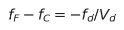
Red (f_C) and blue (f_F) focal-length difference of a single lens: proportional to focal length, inversely proportional to Abbe number
This means a longer focal length and stronger glass dispersion give worse chromatic aberration. For a single crown lens with f=200 mm and V=60, the focal difference between just the visible C and F lines is about 3.3 mm; the span from 633 nm to 1064 nm is larger still, and a several-millimetre focal separation between two wavelengths is a common magnitude for ordinary field lenses — unacceptable in precision processing systems.
2.2 Axial and lateral chromatic aberration: two different kinds of ‘splitting’
Chromatic aberration has two manifestations, which must be distinguished during selection:
| Type | English | Manifestation | Dependence on field |
|---|---|---|---|
| Axial chromatic aberration (longitudinal / positional) | Axial / Longitudinal Chromatic Aberration | Foci of different wavelengths separated along the optical axis | Present across the whole field, on and off axis, roughly the same magnitude |
| Lateral chromatic aberration | Lateral / Transverse Chromatic Aberration (Chromatic Difference of Magnification) | Different magnification at different wavelengths, so image height varies with wavelength | Zero on the optical axis, growing linearly with off-axis distance (field), largest at the field edge |
A common misconception needs clarifying here: lateral chromatic aberration does not cause a ‘scan-centre shift’. The scan centre lies on the optical axis, where on-axis image height is zero and every wavelength focuses at the same point — there is no lateral displacement. The real harm of lateral chromatic aberration is inconsistent scale between two wavelengths at the field edge — the coordinate system calibrated with 633 nm red vision and the 1064 nm infrared processing system coincide at the field centre but diverge increasingly towards the edge, showing up as the red-drawn scan field differing in size from the actual IR-processed field and graphic edges misaligning. For a coaxial vision system that ‘calibrates with red and processes with infrared’, axial aberration determines ‘focal-plane coincidence’ and lateral aberration determines ‘coordinate-scale coincidence’ — both must be corrected.
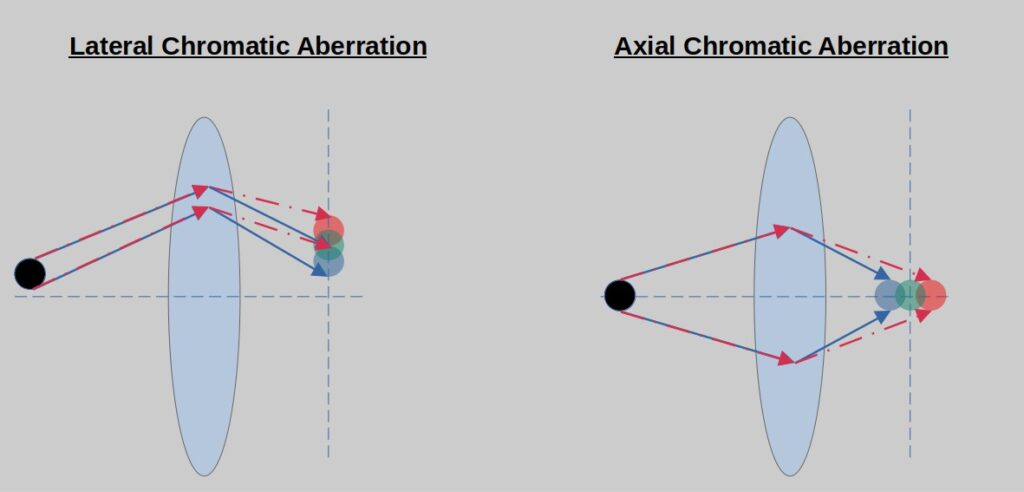
Figure 1 Axial chromatic aberration (foci separated along the axis) and lateral chromatic aberration (magnification differs by wavelength, zero on axis and largest at the edge)
Source: Edmund Optics
2.3 The achromatic principle: positive and negative lenses with complementary dispersion
The core idea of achromatisation is to ‘fight fire with fire’: combine a low-dispersion crown-glass positive lens with a high-dispersion flint-glass negative lens (usually cemented as a doublet, or separated with an air gap), so the dispersions they produce are equal in magnitude and opposite in direction, cancelling each other while retaining positive total power. In the thin-lens approximation, the achromatic condition is:
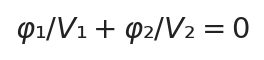
Achromatic condition: the two lenses’ powers are apportioned inversely to their Abbe numbers so the dispersions cancel
At the same time, the system’s total power must meet the application requirement:
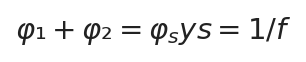
Total power equation: the combination remains a positive-power (converging) system
Solving the two equations gives the power distribution between the two lenses:

Achromatic doublet power solution: the crown positive lens (1) has positive power, the flint negative lens (2) negative power
Since crown V₁ > flint V₂, the denominator is positive, φ₁ is positive and φ₂ negative: the positive lens does most of the converging, while the negative lens cancels dispersion and contributes a little divergence. This is the classic achromatic doublet design, established in the 18th century. Apochromats go further, bringing three wavelengths to a common focus and suppressing the secondary spectrum, requiring special low/abnormal-dispersion glasses (such as fluorite or fluor-crown) at significantly higher cost.
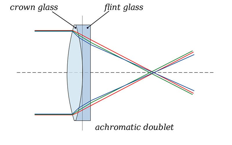
Figure 2 Achromatic doublet: a crown positive lens and flint negative lens cemented, with the two wavelengths focusing together
Source: Wikipedia / optics textbooks
2.4 Hybrid refractive/diffractive achromatisation
Another technical route is to fabricate a diffractive optical element (DOE) on the surface of a refractive lens. A diffractive element’s dispersion is opposite to that of refractive materials: its equivalent Abbe number in the visible band is negative:

Equivalent Abbe number of a diffractive element: determined only by wavelength, not material, about −3.45 in the visible band
A refractive lens has a longer focal length at longer wavelengths, while a diffractive lens has a shorter one — naturally complementary — so hybrid refractive/diffractive designs can achieve broadband achromatisation with fewer elements. This is mature commercially in camera telephoto lenses (such as Canon DO and Nikon PF lenses). In laser F-Theta field lenses, hybrid schemes are limited by diffraction efficiency (stray orders at non-design wavelengths) and the lower laser-damage threshold of the microstructures, remaining a high-end/specialist option; mainstream industrial products are still all-refractive multi-element groups.
2.5 The field lens’s threefold task: achromatisation × flat field × linear scanning
An ordinary achromatic doublet cannot serve as an achromatic field lens — it solves only ‘two wavelengths focusing together’, flattening neither the field nor guaranteeing scan linearity. An industrial achromatic field lens must accomplish four mutually constraining tasks simultaneously:
- Correct axial chromatic aberration for two/multiple wavelengths: design-wavelength foci coplanar;
- Correct lateral chromatic aberration: magnification consistent across wavelengths, scan fields coincident;
- Flatten the field (correct field curvature): foci across the whole field lie in one plane;
- F-Theta linearisation: introduce controlled barrel distortion so image height is proportional to scan angle.
An ordinary lens follows y′ = f·tanθ (nonlinear — beyond large angles the spot moves increasingly fast and scanning distorts); an F-Theta lens deliberately introduces negative distortion to correct this to:
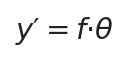
(θ in radians); the F-Theta linear relation means the spot moves at constant speed on the work surface as the galvanometer deflects uniformly
The scan field is determined by focal length and maximum scan angle:
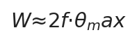
Scan field (order of diagonal / circle diameter): a rule of thumb gives field side length ≈ 0.7f (mm to mm)
To balance a long working distance with a large field, F-Theta lenses commonly use a retrofocus structure (negative-power front group + positive-power rear group) to shift the principal plane rearward; for cutting and drilling with demanding perpendicularity, a telecentric design is further used so the chief ray is nearly perpendicular to the work surface across the field. Adding dual-wavelength achromatisation on top of such multi-element configurations leaves optical design freedom extremely tight, so achromatic field lenses are usually complex groups of 3–8 elements in several glass types, jointly optimised over the full field and both wavelengths by optical design software — the root reason they cost more and have a higher design threshold than ordinary lenses of the same aperture, rather than being a matter of ‘one more coating layer’.
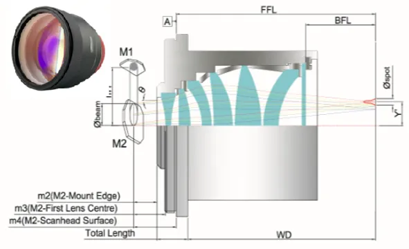
Figure 3 Cross-section of an industrial F-Theta multi-element lens group (retrofocus layout, with FFL/BFL/WD dimensions and galvanometer position)
2.6 Ultrafast-laser scenarios: bandwidth and group-delay dispersion
A femtosecond pulse is not strictly monochromatic. From the Fourier-transform limit, a Gaussian pulse’s spectral bandwidth and duration satisfy:
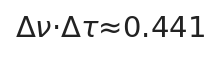
Fourier-transform limit (Gaussian pulse): the shorter the pulse, the broader the spectrum
Converted to wavelength bandwidth:

Wavelength-bandwidth conversion: λ centre wavelength, c speed of light, Δτ pulse duration
Numerically: at a 1030 nm centre wavelength, a 100 fs pulse has about 15.6 nm bandwidth and 50 fs about 31.2 nm; at 1064 nm, 100 fs is about 16.7 nm. An ordinary single-wavelength field lens can have axial chromatic aberration of tens of micrometres across such bandwidths — enough to elongate the focus, lower peak power density and degrade processing edges. Ultrafast scenarios should therefore use dedicated broadband/low-dispersion field lenses, and besides axial chromatic aberration also watch group-delay dispersion (GDD) — dispersion from lens materials and coatings broadens the pulse, so manufacturers should supply GDD specifications. Note: such ‘femtosecond broadband lenses’ target ‘continuously low aberration over one broad band’, a different design emphasis from the ‘two discrete wavelengths confocal’ achromatic field lens; treat them separately when selecting.
3. Structure and Classification
3.1 By wavelength combination (most relevant to selection)
| Wavelength combination | Typical use | Market commonness |
|---|---|---|
| 1064 + 633/635/650nm | Fibre laser marking/welding + red coaxial vision alignment or red alignment (the most mainstream combination) | ★★★★★ standard across vendors |
| 1064 + 532nm | IR deep engraving/cutting + green fine processing, with a convenient 2:1 wavelength ratio | ★★★★ common |
| 355 + 635nm | UV micromachining + red vision/alignment (UV is invisible, so alignment light is essential) | ★★★★ common |
| 355 + 532nm / 355 + 405nm | UV + green/blue-violet dual-wavelength fine processing | ★★★ optional |
| 355 + 1064nm | UV + IR combined processes (actual products mostly small fields, e.g. EFL100 mm / 40×40 mm class) | ★★ special order |
| 532 + 635 nm (often telecentric) | Green processing + red vision, telecentric configuration for high-precision micromachining | ★★★ optional |
| 808/850/980 + 635 nm, 1940 + 635 nm | Semiconductor/medical laser processing + red alignment | ★★ special order |
| 1064 + 450nm | IR + blue combined (blue has advantages on highly reflective materials such as copper), mostly fused-silica hybrid water-cooled versions | ★★ special order |
| Broadband around 1030 nm (±10–20 nm) | Femtosecond/picosecond ultrafast processing, low aberration and low GDD across the band | ★★★ ultrafast-specific |
It should be clarified that an F-Theta field lens is a laser scanning processing component. Laser display/RGB projection uses projection objectives or dedicated scanning lenses, and laser confocal microscopes use microscope objectives — although these also involve achromatisation, their optical configurations and aberration-balancing goals differ from an F-Theta lens and they should not be conflated.
3.2 By telecentricity
- Non-telecentric (standard) achromatic field lens: the chief ray at the field edge is tilted to the work-surface normal (typical telecentric angle 4°–17°). Relatively simple, fewer elements and low cost, suited to marking and ordinary cutting where edge perpendicularity is not critical.
- Telecentric achromatic field lens: the chief ray is nearly perpendicular to the work surface across the field (telecentric angle < 4°, high-end < 2°), with uniform spot size, no perspective error and good sidewall perpendicularity in cutting/drilling. Complex, bulky and expensive, suited to precision micromachining, PCB/FPC drilling and semiconductor dicing.
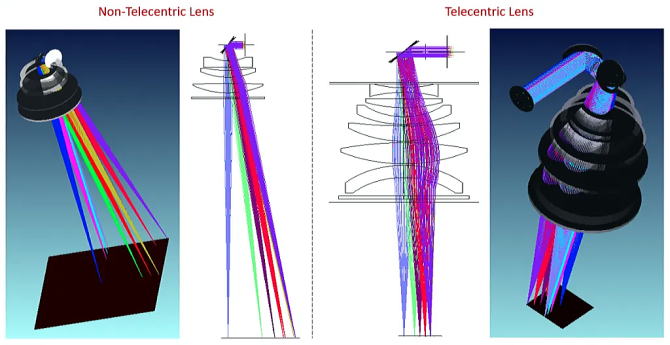
Figure 3b Optical-path comparison of non-telecentric (multi-wavelength oblique incidence, dispersion separated) and telecentric achromatic (full-field perpendicular incidence, dual-wavelength confocal) field lenses
3.3 By material and configuration
- All-optical-glass cemented/separated type: the mainstream solution. Combinations of crown, flint and other glass types give ample achromatic design freedom and moderate cost; suited to regular power.
- Fused-silica + optical-glass hybrid type: in high-power scenarios the elements bearing the most energy use fused silica (low absorption, high damage threshold), while flint glass is retained for achromatisation, often with a water-cooled mount (models commonly carry a WC suffix).
- Hybrid refractive/diffractive type: see section 2.4, a high-end special option.
Note one material-selection detail: fused silica is not the ‘universal first choice’ for achromatic field lenses. Fused silica has a very high Abbe number (very weak dispersion) and few available glass types, making it hard to assemble the power-to-dispersion ratio achromatisation needs; pure fused-silica field lenses are almost always single-wavelength designs. An achromatic field lens must introduce several dispersive glasses, so mainstream products use optical glass; only high-power water-cooled models mix fused silica into critical elements.
4. Key Parameters in Detail
| Parameter | Typical range / description | Selection significance |
|---|---|---|
| Design wavelength pair | E.g. 1064/635, 1064/532, 355/635 nm; each product is achromatised only for the marked wavelength set | First decision item. List all wavelengths needing confocal operation in the system (processing + vision + alignment + harmonics) and match the pair exactly; away from the design wavelength chromatic aberration returns unchanged |
| Effective focal length EFL (f) | Measured across achromatic products about 56–400 mm | Determines field (side ≈ 0.7f) and spot (∝f). Field and spot are a trade-off: fix the field first, then verify the spot |
| Scan field | Measured across achromatic products about 18×18 mm to 212×212 mm (growing with focal length) | Allow 20%–30% margin over the actual processing graphic; check whether the figure is a square side or a circle diameter |
| Entrance pupil (allowable beam diameter) | Measured across achromatic products about 6–30 mm | Must be ≥ the galvanometer output beam diameter. Chain iron rule: laser output × expansion ratio ≤ galvanometer aperture ≤ field-lens entrance pupil; clipping the pupil causes vignetting, spot widening and stray light |
| Focused spot diameter | About 10–50 μm, depending on wavelength, focal length and entrance pupil | Sets processing line width and power density; for dual-wavelength systems check both spots separately (vision wavelength sets calibration accuracy, processing wavelength sets machining accuracy) |
| Working distance WD | Non-telecentric WD≈(0.85–1.0)f; telecentric WD can be markedly larger than f | The mechanical distance from the last lens surface to the focal plane, ≠ focal length; determines fixture height and space for air-knife/nozzle, protective window and coaxial camera — always follow the maker’s mechanical drawing |
| Telecentric angle | Standard type 4°–17°; telecentric type <4°, high-end <2° | Smaller gives more uniform edge spots and better kerf perpendicularity; telecentric types restrict field and cost more, unnecessary for ordinary marking |
| Residual axial chromatic aberration | In quality designs the two-wavelength focal-plane coincidence is within the depth of focus | Directly determines whether the vision and processing focal planes coincide — request measured two-wavelength focus-shift curves from the maker rather than single-wavelength data |
| F-Theta linearity error | Generally ≤1%–2%, precision types <0.5% | Sets geometrical accuracy for large graphics; achromatic models also require consistent linearity error across the two wavelengths |
| Transmittance / absorption | After dual-wavelength AR coatings, per-band transmittance commonly >95%–98% | The coating must transmit all design wavelengths with high efficiency; absorption drives thermal focal drift, so kW-class needs low-absorption glass plus water cooling |
| Damage threshold / GDD | For pulsed operation distinguish ns/ps/fs conditions; ultrafast scenarios also check GDD | CW is checked by average power density, pulsed by peak fluence; ultrafast lenses need GDD confirmation to avoid pulse broadening |
| Mounting interface | Mainstream measured M85×1; also M79×1, M102×1, M58×1, M55×1, M92×1, flanges, etc. | Must match the galvanometer flange; pitch is mostly 1 mm — install to the specified torque and centre carefully |
4.1 How to calculate spot diameter: three coefficient conventions
Different sources give different spot-formula coefficients (1.27, 1.83, 2.44) — none is simply right or wrong; they reflect different definitions of spot diameter:
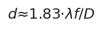
Manufacturer engineering convention (common in LINOS/Qioptiq, Ronar-Smith datasheets): combines beam quality and actual energy distribution, used for selection estimates

Gaussian-beam convention: D is the beam’s 1/e² diameter, coefficient 1.27 for M²=1 fundamental mode
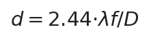
Airy-disc convention: the first-dark-ring diameter of diffraction by a uniformly illuminated circular aperture (1.22 is the radius coefficient)
Relationship: 2.44 is the Airy-disc diameter for an ideal uniform beam; 1.27 is the 1/e² diameter of a fundamental Gaussian beam; 1.83 is a manufacturer’s engineering compromise among real beam quality (M²>1), energy enclosure and effective machining aperture. For selection estimates it is advisable to use the manufacturer’s datasheet convention of 1.83 with margin. Worked example: f=210 mm, D=30 mm, 1064 nm, d≈1.83×1.064×210/30≈13.6 μm, matching mainstream vendors’ quoted values for this specification.
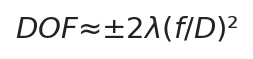
Rayleigh depth-of-focus order: depth of focus is proportional to the square of the f-number, so short-focal-length large-aperture lenses have shallow focus and are more sensitive to focusing and residual chromatic aberration
5. Characteristics: Advantages and Limits
Advantages:
- Multi-wavelength confocal and coplanar, so coaxial vision systems achieve ‘what you see is what you mark’, with vision alignment down to sub-pixel / ±20 μm and no software coordinate-offset compensation;
- Dual/triple-wavelength equipment shares one field lens, switching processes by wavelength without changing lenses or refocusing, improving cycle time and repeatability;
- The red alignment beam (635/650 nm) is strictly confocal with the processing laser — the alignment spot is the processing position, friendly to machine setup and teaching;
- Telecentric achromatic types maintain perpendicular incidence and consistent spots across the field, combining high precision with multi-wavelength capability.
Limits and costs:
- Effective only for the design wavelength pair, not ‘achromatic at all wavelengths’; focus shift grows rapidly away from the design values;
- Many elements, complex glass types and coatings that must optimise several bands simultaneously make it markedly more expensive than an ordinary lens of the same specification;
- Optical glass has more pronounced absorption and thermal-lens problems at high power, limiting ultra-high-power selection;
- Achromatisation does not exempt thermal drift: even at the design wavelength, lens heating causes overall focal drift; kW-class needs low-absorption glass + water cooling + Z-axis compensation;
- The broader the coating band, the thicker the film and the greater the stress and absorption, with lower yield — in practice achromatic field lenses cover only 2–3 specific bands (e.g. 532±15 nm, 1064±30 nm); there is no ‘universal broadband field lens’.
6. Typical Applications and Selection Guidance
6.1 Four typical applications
- Coaxial-vision precision marking/welding (1064 + 633/635/650 nm): essential for consumer electronics, IC chips and PCB coding with automated handling and flying marking. The camera images and locates through red illumination, and the IR laser processes within the vision coordinates; focal-plane coincidence plus scale consistency is the prerequisite for sub-pixel positioning.
- Multi-wavelength coaxial combined processing (1064+532, 355+635, etc.): IR deep engraving/welding and green/UV fine operations on one machine in one optical path — switching the programme’s wavelength switches the process.
- UV processing + red alignment (355+635 nm): UV light is invisible, so focusing and teaching rely entirely on the alignment light; achromatisation ensures the alignment point is the processing point. Common in FPC cutting and glass/sapphire processing.
- Ultrafast-laser micromachining (1030 nm broadband): dedicated broadband lenses with low aberration and low GDD across the femtosecond bandwidth keep the focus from elongating and the pulse from broadening, used for transparent-material cutting and microstructure fabrication.
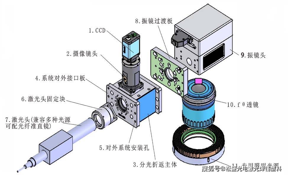
Figure 4 Coaxial-vision marking optical path: the illumination source is coaxial with the processing laser through a beam splitter, and camera and laser share the path through the galvo and field lens, achieving ‘what you see is what you mark’
6.2 Six-step selection process
- List the wavelengths: write down all wavelengths in the system needing confocal operation and their roles (processing/vision/alignment/harmonics), and select the model by wavelength pair — if the pair does not match, nothing else matters;
- Set the field: size the field as the largest graphic +20%–30% margin, then infer focal length from field ≈ 0.7f;
- Verify the spot: use d≈1.83λf/D to check the shortest wavelength (usually the finest operation) meets line-width/power-density requirements;
- Check the aperture chain: laser output × expansion ratio ≤ galvanometer aperture ≤ field-lens entrance pupil — any link over the limit is a deal-breaker;
- Set telecentricity: choose telecentric (<4°) for cutting/drilling/deep engraving, standard type suffices for flat marking;
- Verify power/ultrafast: above several hundred watts average power confirm glass absorption and water cooling; picosecond/femtosecond scenarios additionally verify GDD and pulse damage threshold; finally check the mounting thread and WD on the mechanical drawing.
6.3 Decision tree: when must you use an achromatic field lens
| Question | Conclusion |
|---|---|
| Do two or more wavelengths in the same galvo path need to focus sharply at once (processing + vision/alignment, or dual-wavelength processing)? | Yes → an achromatic field lens for the corresponding wavelength pair is required |
| Single-wavelength processing only, with the red alignment beam used merely for rough preview and not vision positioning? | An ordinary single-wavelength field lens suffices (slight red defocus is acceptable if visible to the eye) |
| Femtosecond/picosecond ultrafast laser (pulse width < hundreds of fs)? | Choose an ultrafast-specific broadband low-dispersion lens (check bandwidth and GDD), not an ordinary dual-wavelength achromatic model |
| Cutting/drilling/deep engraving, sensitive to edge perpendicularity? | Telecentric type (telecentric achromatic if multiple wavelengths are needed) |
6.4 Mainstream manufacturers and real product references
Mainstream suppliers of achromatic F-Theta lenses are specialist laser-optics makers. The following parameters come from public catalogues (using Ronar-Smith® / Wavelength Opto-Electronic public specification tables as an example, to establish orders of magnitude):
| Model | Wavelength (nm) | EFL(mm) | Field (mm) | Entrance pupil (mm) | Telecentric | WD(mm) | Interface |
|---|---|---|---|---|---|---|---|
| SLA-1064-635-100-163 | 1064/635 | 163 | 100×100 | 12 | No | 157.6 | M85×1 |
| SLA-1064-630-150-254 | 1064/635 | 254 | 150×150 | 30 | No | 306.9 | M102×1 |
| SLA-1064-635-200-360 | 1064/635 | 360 | 200×200 | 30 | No | 358.4 | M85×1 |
| SLA-1064-532-100-163 | 1064/532 | 163 | 100×100 | 12 | No | 159.7 | M85×1 |
| SLA-1064-532-175-254 | 1064/532 | 254 | 175×175 | 15 | No | 262.8 | M85×1 |
| SLA-355-635-110-220 | 355/635 | 220 | 110×110 | 10 | No | 166.3 | M85×1 |
| SLA-355-532-90-170 | 355/532 | 170 | 90×90 | 10 | No | 125.6 | M85×1 |
| SLA-355-1064-40-100 | 355/1064 | 100 | 40×40 | 10 | No | 43.5 | M58×1 |
| TSLA-1064-633-30-75 | 1064/633 | 75 | 30×30 | 10 | Yes | 50.3 | M79×1 |
| TSLA-1064-532-60-110 | 1064/532 | 110 | 60×60 | 10 | Yes | 56.7 | M85×1 |
| TSLA-532-635-60-150 | 532/635 | 60×60 | 15 | Yes | 79.5 | Flange |
Other verifiable international suppliers include Sill Optics (German, S4LFT multispectral/telecentric F-Theta line), Edmund Optics (multispectral F-Theta scanning lenses) and Thorlabs (F-Theta field lens series). It should be noted that manufacturers such as Scanlab focus on galvanometers (scan heads) and do not themselves produce field lenses — their systems use field lenses from specialist optics makers, so confirm the compatible-lens list with the galvanometer vendor. Domestically, Wavelength Opto-Electronic and CASTECH have field-lens R&D capability, localisation is fairly mature in the low/mid range, and high-end telecentric achromatic products continue to break through.
6.5 Use and maintenance
- Cleaning: gently wipe the coated surface in one direction with lint-free lens tissue or a non-woven cloth with analytical-grade alcohol or an ethanol/ether mix, avoiding dry and repeated wiping; keep dust covers on in daily use.
- Back-reflection protection: when processing highly reflective materials, the workpiece reflection can form a secondary focus on the lens surface and damage the coating; add an optical isolator or tilt the lens mount in high-power/ultrafast scenarios.
- Installation and centring: the lens optical axis must be coaxial with the galvanometer path; tighten the thread to the specified torque, since tilt introduces decentration aberration — telecentric types are more sensitive to alignment.
- Environment: control dust and humidity; in welding/cutting add air blowing and protective windows to prevent fumes contaminating the first lens surface and causing local overheating.
7. Common Misconceptions
| ✕ Misconception | ✓ Correction |
|---|---|
| An achromatic field lens is achromatic at all wavelengths | It corrects only the design wavelength pair (e.g. 1064/635 nm). Run it at 532 nm and chromatic aberration returns; the further from the design wavelength, the larger the focus shift |
| Single-wavelength systems should also buy an achromatic lens for a better spot | There is no benefit for a single wavelength. Achromatisation solves ‘multi-wavelength focus separation’, not single-wavelength spot quality, and costs more |
| Lateral chromatic aberration causes a scan-centre shift | Lateral (magnification) chromatic aberration is zero on the optical axis, so the centre does not shift; it makes the two wavelengths’ magnification/scale differ at the field edge, with misalignment growing towards the edge |
| An achromatic doublet can serve as an achromatic field lens | A doublet only brings two wavelengths to one focus; it neither flattens the field nor linearises the scan — using it directly defocuses the field edge and distorts graphics |
| Working distance WD is the focal length f | f is an optical parameter, WD a mechanical one. Non-telecentric WD≈0.85–1.0f, telecentric WD can be much larger than f; fixture height always follows the mechanical drawing |
| Achromatisation means no focal drift | Chromatic aberration is a ‘difference between wavelengths’, thermal lensing an ‘overall temperature-rise drift’ — different things. Even the design wavelength drifts after the lens absorbs heat; kW-class needs low absorption + water cooling + Z-axis compensation |
| The broader the lens coating band, the better — ideally universal | Broader-band coatings are thicker, more stressed, more absorbing and lower-yield. Achromatic field lenses fine-tune only 2–3 specific bands; band matching is the right approach |
| An achromatic field lens must be made of fused silica | Fused silica has weak dispersion and few glass types, making it hard to form an achromatic pair on its own; mainstream achromatic lenses use several optical glasses, with fused silica mixed into critical elements only in high-power water-cooled models |
| A femtosecond laser just needs a dual-wavelength achromatic field lens | Femtosecond bandwidth reaches tens of nanometres (100 fs @1030 nm ≈ 15.6 nm), requiring a broadband low-dispersion lens with GDD verified; discrete dual-wavelength correction cannot replace continuous broadband correction |
| Galvanometer vendors (e.g. Scanlab) produce their own matching achromatic field lenses | Scanlab’s core business is galvanometers/scan heads; field lenses come from specialists such as Sill and Ronar-Smith — request the official compatibility list |
| The longer the focal length, the more ‘advanced’ | Long focal length = larger field but a coarser spot (d∝f) and lower power density; fine processing instead wants short focal length and a small field — matching the need is optimal |
| An entrance pupil slightly smaller than the beam diameter is not a big issue | Clipping causes vignetting: a sharp edge-energy drop, enlarged spot, stray light and heating, with uneven processing around the field; the pupil must exceed the beam diameter throughout |
| Spot-formula coefficients 1.27/1.83/2.44 contradict each other | They reflect different conventions: 1.27 is the 1/e² diameter of a fundamental Gaussian beam, 2.44 the Airy-disc diameter and 1.83 the manufacturer’s engineering convention — use the datasheet convention consistently with margin |
| Achromatic field lenses can be used for laser projection / confocal microscopes | F-Theta lenses are designed for laser scanning processing; projection uses projection objectives and confocal uses microscope objectives, with different aberration-balancing goals — they cannot be interchanged |
8. History and Development Trends
The achromatic lens is a classic optical invention: in 1733 the English lawyer and optics enthusiast Chester Moore Hall first made an achromatic doublet, in 1758 John Dollond patented and commercialised it, and subsequently Joseph von Fraunhofer, Ernst Abbe and Otto Schott established systematic glass science and aberration theory — the Abbe number is precisely the glass-dispersion metric Ernst Abbe proposed in the 19th century. The F-Theta scanning field lens matured with the industrialisation of laser marking and galvo scanning in the late 20th century, and the achromatic F-Theta lens is a product of the spread of coaxial-vision processing and multi-wavelength laser systems over the past two decades.
Current trends:
- Ultrafast adaptation: low-aberration, low-GDD field lenses for femtosecond/picosecond broad spectra are a development focus, matching the industrialisation of hundred-watt ultrafast lasers;
- Higher power: low-absorption glass, fused-silica hybrid designs and water-cooled mounts support kilowatt-class multi-wavelength processing;
- Three wavelengths and ultrabroadband: moving from dual to 355/532/1064 nm triple-wavelength confocal, with apochromatic designs trickling down;
- Galvo-lens-vision integration: joint optimisation of the lens with the galvanometer and coaxial camera module reduces alignment error;
- Domestic substitution: low/mid-range achromatic field lenses are largely localised, with continuing breakthroughs in telecentric, ultrafast and deep-UV high-end categories.
9. References and Further Reading
- RP Photonics Encyclopedia, Abbe Number — https://www.rp-photonics.com/abbe_number.html
- RP Photonics Encyclopedia, Chromatic Dispersion — https://www.rp-photonics.com/chromatic_dispersion.html
- Edmund Optics, Introduction to Aberration Theory — https://www.edmundoptics.com/knowledge-center/application-notes/optics/introduction-to-aberration-theory/
- Wikipedia, Achromatic Lens — https://en.wikipedia.org/wiki/Achromatic_lens
- ISO 10934, Optics and optical instruments — Vocabulary (definitions of chromatic aberration, achromatism and apochromatism)
- Wavelength Opto-Electronic (Ronar-Smith®), F-Theta Lenses / Achromatic Scan Lenses catalogue — https://wavelength-oe.com/zh-CN/f-theta-lenses
- Sill Optics, F-Theta Lenses — https://www.silloptics.de/en/products/laser-optics/f-theta-lenses/
- Thorlabs, F-Theta Lenses Tutorial — https://www.thorlabs.com/zh/f-theta-lenses-tutorial
Further reading
- F-Theta field lens encyclopedia: flat-field focusing and linear scanning principles explained
- Laser beam expander encyclopedia: beam expansion and focused-spot control
- Laser collimator encyclopedia
- Ultrafast laser encyclopedia: femtosecond pulses and harmonic wavelengths
- Telecentric achromatic field lens selection guide (technical article)
- Laser protective window encyclopedia: selection and materials for protection windows at every station in cutting/welding/galvo/field-lens paths
Related product recommendations
Soar Laser offers a full range of F-Theta field lenses, achromatic/dual-wavelength lenses, telecentric lenses, beam expanders and optics for galvo scanning systems, covering mainstream wavelengths of 1064 nm fibre, 532 nm green, 355 nm UV and femtosecond ultrafast — provide your wavelength combination, field and beam diameter for selection support: hotline 15927220467.
Leave a Reply