


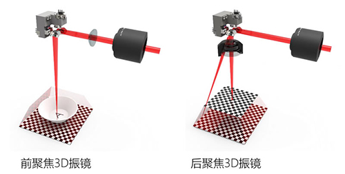
As demand keeps growing for marking on curved surfaces, steps, cones, deep engraving and large areas, the “3D galvo scanner” has become a common configuration on high-end laser equipment. Yet under the same name, the market offers two fundamentally different optical architectures: “pre-focus (pre-scan)” and “post-focus (post-scan)”. Many buyers and engineers get tangled up in these two terms during selection, and some are even misled by sales materials. Starting from the optical principles, this article explains the structure, pros and cons, speed differences and applicable scenarios of both in one pass.
- For conventional 300×300–500×500mm work areas where a suitable F-theta field lens can be matched, choose post-focus 3D first (galvo + field lens + short-travel Z axis): flat-fielding is done optically by the field lens, the Z axis only follows height differences and barely moves on flat work, and the XY galvos can scan at full speed throughout — faster, and the complete machine costs no more than pre-focus.
- Only two situations call for falling back to pre-focus 3D (long-travel dynamic focus ahead of the galvo, usually without a field lens): (1) the work area is so large that no suitable F-theta field lens can be found on the market (meter-class, approx. 2.4m extra-long areas); (2) the workpiece height difference/depth exceeds the Z-axis travel of post-focus 3D (commonly on the order of ±30mm) and a post-focus solution with a longer Z axis cannot be customized.
- The overall machine prices of the two are close: pre-focus has a large-travel Z axis and an expensive dynamic module but saves the field lens; post-focus has a short Z axis but must add an F-theta lens, so the costs cancel out. The real decision criterion is “work area × height difference”, not price or the “3D” marketing label.
1. First, get the concept straight: what do “pre” and “post” actually mean
To judge whether a system is “pre-focus” or “post-focus”, look at only one thing: whether the focusing (focal adjustment) action happens before or after galvo scanning.
- Pre-focus (pre-scan / pre-objective): the laser first passes through a movable dynamic focusing lens group (Z axis) to complete focusing/focal adjustment, then enters the X and Y galvanometers for deflection scanning — that is, “focus first, scan second”.
- Post-focus (post-scan / post-objective): the laser is first deflected by the X and Y galvanometers, then converges onto the workpiece through the focusing lens (usually an F-theta field lens) — that is, “scan first, focus second”.
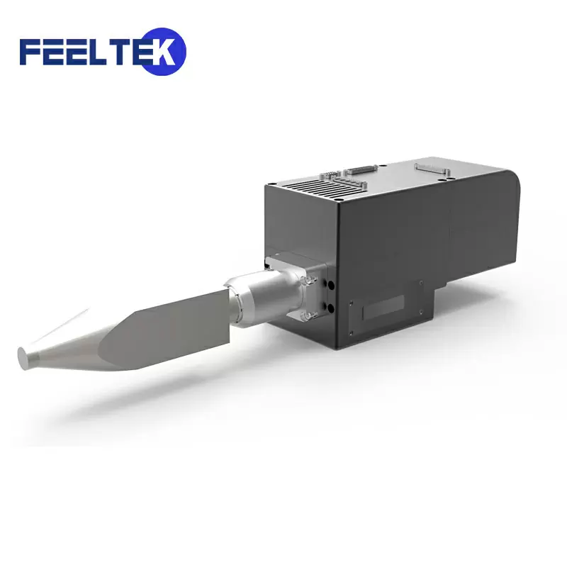
A conventional 2D laser scanning galvo marking machine (galvo + fixed F-theta field lens) is a post-focus structure; adding a short-travel Z-axis dynamic module on top of it gives the post-focus 3D galvo scanner on the market (some vendors call it 2.5D — “F-theta + Z axis” architectures such as the JCZ G3-3D and RAYLASE FOCUSSHIFTER); a system without a field lens that relies on a long-travel dynamic focusing lens group ahead of the galvo to achieve flat-fielding and focal tracking is a pre-focus 3D galvo scanner.
2. How the two architectures work
1. Post-focus (post-scan): the field lens handles flat-fielding, the Z axis only handles height
2D post-focus with a fixed field lens: the collimated beam is first redirected by the two X/Y galvo mirrors, then converged onto the focal plane by the F-theta flat-field lens. Through special optical design, the F-theta lens “flattens” what would otherwise be a spherical focal plane and keeps image height approximately linear with the deflection angle. The limitation is that work area and spot size are constrained by the field lens design: at large deflection angles the edge spot grows and pincushion/barrel distortion appears.
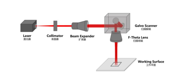
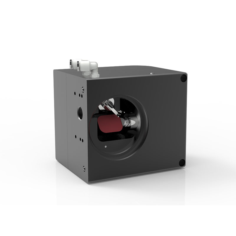
Post-focus 3D with a Z axis: a Z-direction dynamic module is added on top of the F-theta architecture. The key point is the division of labor — flat-fielding across the entire work area is done optically by the F-theta field lens; the Z axis takes no part in flat-fielding and does only two things:
- Following height differences on curved surfaces/steps: when the workpiece surface undulates, the Z axis moves over a small range to compensate defocus;
- Layer-by-layer refocus in deep engraving: as material is removed layer by layer and the machined surface sinks, it tracks and refocuses to prevent the focal point from drifting upward.
The Z axis therefore needs only a small travel (typically on the order of ±30mm, depending on wavelength and field lens) with a light motion load. When marking flat surfaces the Z axis barely moves, and the XY galvos can scan at rated high speed throughout — the fundamental reason post-focus 3D is fast.
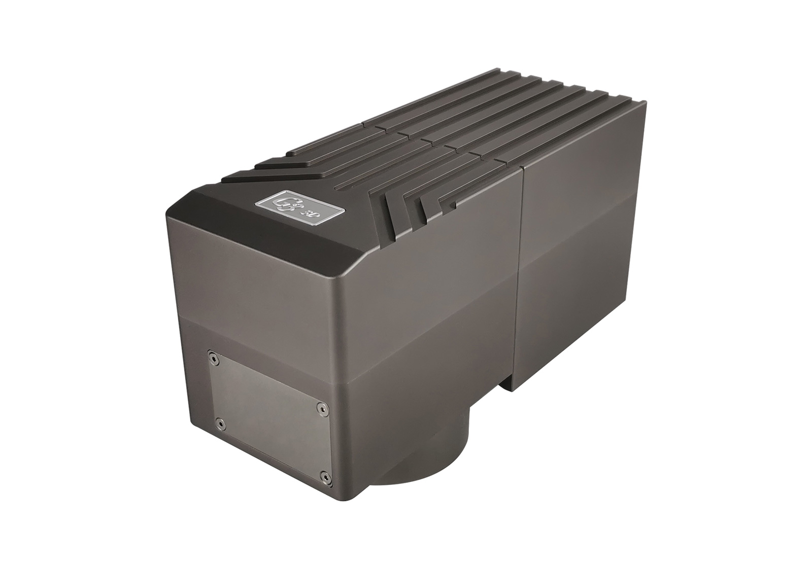
2. Pre-focus (pre-scan) 3D dynamic focus: the Z axis both flattens the field and tracks focus
A dynamic focusing lens group is added before the galvo: it usually consists of a beam expander (a concave lens) movable at high speed along the optical axis plus a focusing lens group, and the system generally carries no F-theta field lens. The control software makes the Z-axis dynamic mirror move in coordination with the X and Y galvos:
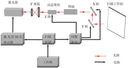
- On flat work, the Z axis must move in real time according to the optical path difference from every scan point to the lens, compensating edge defocus and stretching the spherical focal plane into a flat one — note that even on purely flat work, the Z axis is in continuous motion throughout;
- On curved surfaces/steps/cones, the Z-axis position becomes an arbitrary function of the X/Y positions, keeping the focus fitted to the 3D surface.
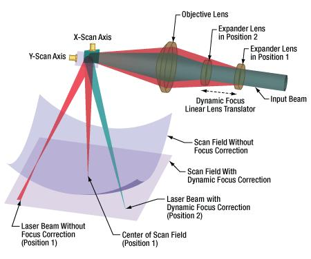
The larger the work area, the greater the Z-axis travel and acceleration required per unit of scan displacement, and the Z-axis bandwidth directly constrains scan speed (high-speed voice-coil focusers such as the Thorlabs BLINK were created precisely to break this bottleneck, with a servo bandwidth of 500Hz). The advantage is that focusing is completed before the galvo and the beam does not move across the objective, so the objective need not be oversized — supporting meter-class and even approx. 2.4m extra-large, extra-long work areas, as well as curved surfaces with height differences of hundreds of millimeters.
3. Key parameters and pros/cons comparison
| Comparison dimension | Pre-focus 3D (pre-scan dynamic focus) | Post-focus 3D (post-scan, Z axis + F-theta) |
|---|---|---|
| Optical path order | Dynamic focus lens (Z) → X/Y galvos → workpiece (usually no F-theta) | X/Y galvos → F-theta field lens → workpiece (Z axis fine-adjusts focus over a small range) |
| Who does the flat-fielding | Z axis dynamically compensates optical path difference point by point (keeps moving throughout even on flat work) | F-theta field lens does optical flat-fielding; the Z axis takes no part |
| Z-axis travel/load | Large: flat-fielding plus full surface compensation; grows with work area | Small (typically on the order of ±30mm); only follows height differences and engraving depth |
| Applicable work area | From 400×400 up to meter-class and approx. 2.4m extra-long areas; the larger the area, the greater its advantage | Areas with a matching field lens: commonly up to 300×300; some wavelengths can use 400/500mm field lenses; beyond that, lenses become expensive and bulky |
| Scan speed | Constrained by Z-axis bandwidth; in large areas the continuously moving Z axis is the bottleneck, and full speed requires a high-frequency focuser | Faster within the field lens’s rated work area: flat-fielding is done optically, the Z axis moves little or not at all, and XY can run at full speed |
| Spot consistency | Real-time compensation across the full area; center and edge can be made highly consistent | Depends on field lens quality; a premium F-theta gives excellent consistency within its rated area |
| Curved surfaces/large height differences | Strong: large Z travel fits 3D surfaces with large height differences (some solutions reach 270mm of height variation) | Can do curved surfaces/steps, but height difference is limited by the short Z travel |
| System cost | Large Z travel and a longer dynamic focus module; cost is mainly in the dynamic axis, but no F-theta field lens is needed | Short Z module, but an F-theta field lens is required (large-aperture lenses are not cheap either). Overall machine prices of the two are close; only the cost composition differs |
| Control and calibration | Complex: three-axis coordination; watch Z-axis linearity, repeatability, thermal drift and bandwidth | Relatively simple: the field lens guarantees the flat field and the Z-axis calibration range is small |
Advantages of pre-focus 3D
- High work-area ceiling: not limited by F-theta aperture; the mainstream solution for inline marking of meter-class and extra-long areas;
- True 3D with large height differences: large Z travel keeps deep cavities, tall protrusions and complex curved surfaces in focus, with no pattern stretching;
- Spot can be made highly uniform across the full area: point-by-point compensation of optical path difference keeps edges sharp;
- Stable deep engraving: the Z axis follows over a large range, so the focus does not drift upward as material is removed layer by layer.
Disadvantages of pre-focus 3D
- Complex calibration: three-axis coordination with a long Z travel places high demands on the dynamic axis’s linearity, repeatability, thermal drift and bandwidth; the overall machine price is close to post-focus 3D — not “a tier more expensive” — the difference lies mainly in cost composition;
- No speed advantage in mid-size areas: the Z axis must compensate continuously throughout even on flat work; the larger the area, the more easily the Z axis becomes the speed bottleneck;
- Higher size/integration demands: large galvo aperture; stricter requirements on beam quality, mounting space and heat dissipation.
Advantages of post-focus 3D
- Fast and efficient within the field lens’s work area: flat-fielding is done optically by the F-theta, the Z axis barely moves on flat work, and XY scans at full speed;
- Mature, reliable and easy to commission: short-travel Z module plus a mature field lens supply chain; low integration barrier and many lens options for conventional 300–500mm areas;
- The volume solution for conventional 300–500mm areas: covers curved surfaces, steps and deep engraving; the mainstream choice in this range;
- Excellent spot consistency with a quality field lens; marking quality is stable within the rated work area.
Disadvantages of post-focus 3D
- Work-area ceiling constrained by the field lens: beyond the economical aperture, large F-theta lenses rise sharply in price and weight and become impractical;
- Surface height difference limited by Z travel: a short-travel Z module suits conventional undulations only; large height differences/deep cavities need pre-focus;
- Edge performance depends on the field lens: with a poorly chosen lens, edge spots enlarge and distortion becomes obvious.
4. Typical application scenarios
| Processing requirement | Recommended architecture | Notes |
|---|---|---|
| Ordinary flat marking, work area ≤300mm | Post-focus 2D/3D | An F-theta is enough; the 3D version also handles some curved surfaces and deep engraving |
| 300/400/500mm areas with curved surfaces, steps and deep engraving of modest height difference | Post-focus 3D | First choice when a matching field lens exists: short Z travel, XY at full speed, faster with a mature supply chain |
| Work areas beyond 500mm, or no suitable F-theta available | Pre-focus 3D (the fallback) | Use Z-axis dynamic flat-fielding as a substitute only when no field lens covers the area |
| Curved surfaces with large height differences, deep cavities, tall 3D parts | Pre-focus 3D | Large Z travel fits complex surface profiles |
| Meter-class sheets, extra-long inline marking | Pre-focus 3D | Scalable to meter-class / approx. 2.4m processing range |
| Small-area precision deep engraving, micro-holes, microstructures | Post-focus 3D (2.5D) | Small clear aperture, high precision, mature solution |
5. Selection advice
- Look at “work area × height difference” first, not the name: within areas where a suitable F-theta field lens can be found (300–500mm), post-focus 3D is always the first choice — fast and simple to commission. Only two situations call for falling back to pre-focus 3D: (1) no F-theta field lens covers the area; (2) a field lens exists, but the workpiece height difference exceeds the post-focus 3D Z-axis travel and a post-focus solution with a longer Z axis cannot be customized. Pre-focus is a choice forced by requirements, not a high-end upgrade.
- Understand where the speed difference comes from: post-focus hands flat-fielding to the optical field lens while the Z axis follows unburdened, so flat work is naturally faster; pre-focus computes a flat field point by point via the Z axis — it wins on work area and height difference, not on speed in mid-size areas.
- Don’t be misled by “price tiers”: overall machine prices of the two architectures are close — pre-focus has a long Z axis and an expensive dynamic module but saves the field lens; post-focus has a short Z module but needs an F-theta. The decision criterion is whether the work area and height difference can be met, not which is pricier or more “high-end”.
- Examine measured Z-axis specs: regardless of architecture, check the dynamic axis’s repeatability, resolution, linearity, 24-hour thermal drift and (especially for pre-focus) servo bandwidth — these determine yield and actual speed on curved surfaces and deep engraving.
- Match wavelength and power: choose field lenses/galvos with coatings matched to 1064nm fiber, 532nm green, 355nm UV or 10.6μm CO₂; for high power, watch optic heat resistance and heat dissipation.
- Ask for the optical path diagram plus sampling on real workpieces: have the vendor state the pre-/post-focus architecture, field lens focal length and Z-axis travel; sample with your own workpiece (ideally with 3D files), focusing the tests on edge spot size, surface distortion, thermal drift in continuous processing and actual cycle time.
6. FAQ
Q1: How can you tell pre-focus and post-focus 3D galvo scanners apart at a glance?
Look at two things: (1) whether there is an F-theta field lens below the galvo scan head — with a field lens it is post-focus; without one, with the beam going straight from the galvo to the workpiece, it is pre-focus; (2) whether the dynamic focusing lens group (Z axis) sits ahead of or behind the galvo — a Z axis ahead of the galvo and doing the flat-fielding means pre-focus; a Z axis that only follows small height changes while the field lens handles flat-fielding means post-focus. The safest approach is to ask the vendor for an optical path diagram directly.
Q2: For the same 300×300, 400×400, 500×500mm work areas, which 3D galvo is faster?
Provided a suitable F-theta field lens can be found, post-focus 3D is faster. In these areas, flat-fielding is done optically by the field lens, the Z axis only follows small workpiece height differences and barely moves on flat work, and the XY galvos can run at full speed throughout; in pre-focus 3D, the Z axis must compensate point by point even on flat work, and a linear motion axis’s speed (a few hundred hertz of bandwidth) can never catch up with galvo deflection (kilohertz level) — the larger the area, the more obvious this becomes.
Q3: Is there a big price gap between pre-focus 3D and post-focus 3D? Is pre-focus the more high-end, more expensive one?
The overall machine prices are roughly the same; only the cost composition differs: pre-focus has a long Z-axis travel and a longer, costlier dynamic focusing module but saves the F-theta field lens; post-focus has a short, cheaper Z module but must add an F-theta field lens (large-aperture lenses are not cheap either), so the costs largely cancel out. Don’t judge the tier by price — the real selection basis is “work area × height difference”.
Q4: When is a pre-focus 3D galvo scanner the only option?
Two situations: (1) the processing area is so large that no F-theta field lens covering it can be found on the market (e.g., meter-class sheets, approx. 2.4m extra-long areas); (2) a field lens exists, but the workpiece height difference/depth exceeds the short-travel Z-axis range of post-focus 3D and a post-focus solution with a longer Z axis cannot be customized (deep cavities, tall protrusions, complex curved surfaces with large height differences). In all other cases, conventional 300–500mm areas should choose post-focus 3D first.
Q5: How large is the Z-axis travel of post-focus 3D? How deep a relief or how large a curve can it handle?
Common post-focus 3D systems have a Z focusing range on the order of ±30mm (exact values vary with wavelength, field lens focal length and vendor design; refer to spec sheets). That is enough for ordinary curved surfaces, steps, nameplate reliefs and layered deep engraving; but if the product has height differences of over a hundred millimeters or very deep cavities, verify whether the Z travel suffices — if not, either customize a post-focus solution with a longer Z axis or switch to a long-travel pre-focus 3D.
Q6: Is a 2D galvo with a Z axis added already “3D”? Are the vendor terms 2.5D and 3D the same thing?
Vendors are inconsistent: FEELTEK calls the “F-theta + Z axis” architecture 2.5D post-focus, while JCZ calls the same architecture a 3D galvo outright (G3-3D). The name doesn’t matter; the optical path does — as long as it is “galvo + F-theta field lens + short-travel Z axis”, it is essentially the post-focus 3D described in this article, while “long-travel dynamic focus ahead of the galvo, no field lens” is pre-focus 3D. When purchasing, state the architecture and Z travel explicitly to avoid confusion over “2.5D/3D” wording.
Q7: Without a field lens, will the edge spot of a pre-focus 3D grow large and blurry over large areas?
It does not necessarily degrade just because there is “no field lens”. Pre-focus compensates each point’s optical path difference by changing the beam divergence angle via the Z axis, and in theory the center and edge spots can be made highly consistent across the full area — one of its advantages. Actual uniformity depends on the dynamic focusing lens group’s quality, Z-axis positioning accuracy and control calibration; the cost is that the Z axis moves at high speed throughout, demanding high bandwidth and careful calibration — not that edges are inherently blurrier.
Q8: When requesting quotes or samples from galvo vendors, which parameters and verifications matter most?
At minimum: (1) an optical path diagram stating the pre-/post-focus architecture; (2) field lens focal length/work area (post-focus) or maximum processing area; (3) Z-axis travel, repeatability, resolution, linearity; (4) Z-axis servo/response bandwidth and the actual marking speed curve; (5) 24-hour thermal drift; (6) matching of wavelength, power and coating. Ideally, sample with your own workpiece (including 3D files), focusing on edge spot, surface distortion, deep-engraving consistency, thermal drift in continuous processing and true cycle time.
Conclusion
Further reading
- What Is an F-Theta Lens? How the “Flat-Field Magic” in Laser Marking Machines Works
- Laser Scanning Galvo: Principles and Applications
- What Is a Galvo? The Little Scanning Mirror Inside Laser Marking Machines
- Achromatic Field Lens: F-Theta Selection for Dual-Wavelength Confocus and Coaxial Vision
- What Is a Beam Expander? Principles, Types and Selection Pitfalls
- What Is Laser Marking? How Permanent Marks Are Created on Materials
- The Ultimate Guide to Laser Field Lens Selection
- Laser Galvo Scanner Selection Guide
Leave a Reply