


What Is an Optical Window? The Transparent Door of a Laser System
The window is the least conspicuous component in a laser system and the one that gets replaced most often. It does two things: lets the light in and keeps the environment out. Get it wrong and it becomes the weak link of the whole beam path. A parallel plate shifts the beam sideways and stretches the equivalent optical path by (n−1)d; two uncoated faces each reflect about 4% and can send that light back into the resonator; a surface figure error is printed straight onto the transmitted wavefront. This article starts from the displacement and optical path of a parallel plate, puts numbers on wedge, surface figure, Fresnel reflection and thermal lensing, compares six substrate materials, then lands on applications and six common myths.
Contents
- 1. Core Concept: What an Optical Window Is
- 2. How It Works: What a Window Does to the Light
- 3. Key Parameters: Nine Specifications and How to Read Them
- 4. Main Types: From Substrate Material to Functional Window
- 5. Selection in Depth: Displacement, Wedge, Figure, Reflection and Contamination
- 6. Applications: Where Windows Are Fitted
- 7. Common Myths: Six Widespread Misunderstandings
1. Core Concept: What an Optical Window Is
An optical window is a transparent plate with two parallel, or nearly parallel, surfaces. Its job is to separate two environments while letting light through with as little loss as possible. It keeps dust, moisture, corrosive gas, pressure difference and temperature swings away from the delicate optics inside, and absorbs the entire environmental cost itself.
Functionally, a window is a passive element: it generates no light, amplifies none and modulates none, it only provides isolation and a path. That has to be said plainly, because the word window tempts people into assuming gain or beam shaping. There is really only one criterion for a good window: how close it comes to not being there at all.
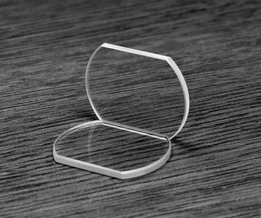
That is also where it differs from a lens or a prism. A lens trades curvature for focusing and a prism trades an angle for deviation; both actively reshape the wavefront. A parallel plate leaves the direction of propagation alone and contributes only a lateral shift and some extra optical path. So what makes a plate a window is its purpose, isolating an environment, not its shape: the same plate becomes an interference element inside an etalon and a window when bolted to a flange.
2. How It Works: What a Window Does to the Light
The effect of an ideal window on a beam splits into four items, and selection is really the business of keeping each of them within an acceptable magnitude:
- Lateral displacement: at oblique incidence the exit beam is parallel to the entrance beam but shifted sideways, and the shift grows with thickness and angle.
- Extra optical path: light travels d inside the medium, which is equivalent to n·d in air, a net addition of (n−1)·d. For a resonator or an interferometer arm, that is a real change in length.
- Surface reflection: about 4% per face when uncoated, roughly 8% for the pair, and the reflected light can travel straight back as harmful feedback.
- Absorption and scatter: bulk absorption, bubbles and striae in the material, plus scratches and dust on the surfaces, all convert a small fraction of the power into heat.
Of these four, the first two are geometric: know the thickness and the refractive index and you can calculate them exactly. The last two are what actually decides the specification, because they determine whether you need a coating, whether the window should be tilted, and how long it will survive at your power level. The geometry comes first, though, because most instances of the beam going astray after a window was fitted come from there.
3. Key Parameters: Nine Specifications and How to Read Them
The datasheet of a window looks dull, but every line maps onto a specific failure. The table below lays out nine parameters, and the last column tells you how each one bites.
| Parameter | Meaning | What goes wrong |
|---|---|---|
| Transmission | Transmitted fraction at a stated wavelength and angle of incidence, including both surface reflections, bulk absorption and scatter | Every 1% of loss in a kilowatt system is 10 W of heat deposited in the window itself, and several plates in series multiply the losses |
| Surface figure | Peak-to-valley deviation from an ideal plane, quoted as λ/10, λ/4 or in fringes, referenced to 633 nm as a rule | Figure error is transferred to the transmitted wavefront at roughly (n−1), about 46% for fused silica; interferometry and tight focusing will show the fringe distortion directly |
| Parallelism (wedge) | Angle between the two surfaces, which sets how far the two reflected beams separate and how much the transmitted beam deviates | Wedge deviates the beam like a very thin prism, and splits the two surface reflections into two ghost images that separate with distance |
| Substrate material | Sets the transmission band, refractive index, thermal expansion, thermal conductivity and strength | A wrong material is rarely a matter of a few percent: germanium is simply opaque in the visible, and some crystals are thermally unstable in ways coatings cannot fix |
| Coating type | Single-wavelength or broadband anti-reflection, one face or both, with a stated design wavelength and angle | A coating works near its design wavelength and angle only; away from them the reflectance climbs quickly, and the coating is also the weakest point for damage |
| Damage threshold | Maximum continuous power density (kW/cm²) or pulse energy density (J/cm²) the window tolerates | Failure above threshold usually starts as coating pits, then absorption and heating, then a fractured plate; contamination lowers the real threshold considerably |
| Clear aperture and thickness | Usable aperture, substrate thickness and the thickness-to-diameter ratio | A thin window over a large aperture deflects under pressure difference, while thickness also sets displacement and absorption, so the three have to be traded off together |
| Surface quality | Scratch-dig specification such as 60-40, 40-20 or 20-10 | Scratches and digs scatter and absorb, and at high power they are where damage begins; the lower the numbers the tighter the spec, and the price rises fast |
| Environmental compatibility | Pressure, humidity and corrosion resistance, plus the way the plate seals to its flange: O-ring, adhesive or metallised seal | The seal sets the leak rate and whether the window can be removed; CaF₂ and ZnSe dislike moisture and heat and will fog or shed their coating in a damp environment |
4. Main Types: From Substrate Material to Functional Window
Windows are classified along two axes, and mixing them up causes most of the confusion. One axis is the substrate material, which fixes the physical limits: what it transmits, how much power it takes, how it behaves when hot. The other is the functional design, which decides what role the window plays in the system: isolation, protection, sampling or attenuation. In practice you cross out the impossible materials first, then pick the function.
| Function | Typical construction | Where it is used |
|---|---|---|
| Single-wavelength AR window | V-coat anti-reflection on both faces, reflectance below 0.2% at the design wavelength | Fixed-wavelength beam paths and cavity isolation |
| Broadband AR window | Multilayer broadband coating, for example 400–700 nm or 650–1050 nm | Tunable sources, shared multi-wavelength paths, imaging |
| Laser protective window | Fused-silica substrate, high-threshold AR coating, mounted in a quick-change frame | End of a cutting or welding head, blocking spatter and fume |
| Vacuum / sealed window | Increased thickness-to-diameter ratio, O-ring or metallised seal, polished face towards the vacuum | Vacuum chambers, gas cells, sealed detector packages |
| Wedge window | Faces at 0.5°–2° to each other so the two reflections separate | High-power feedback control, imaging paths that must avoid ghost images |
| Brewster window | Installed at the Brewster angle, where the p-polarised reflection is theoretically zero | Low-loss intra-cavity window that also acts as a polarisation selector |
| Attenuation window | Metal coating or an absorbing substrate, with optical density calibrated at the wavelength | Fixed attenuation ahead of a detector, switching power ranges |
5. Selection in Depth: Displacement, Wedge, Figure, Reflection and Contamination
5.1 Displacement and Extra Optical Path of a Parallel Plate
When light crosses a parallel plate of thickness d at an oblique angle, it leaves in the same direction but shifted sideways by:
s = d · sin(θ₁ − θ₂) / cos(θ₂), with sin θ₁ = n · sin θ₂
Put in some ordinary numbers: a 10 mm BK7 plate (n ≈ 1.52) at 45° incidence refracts to about 27.7° and shifts the beam by s ≈ 3.4 mm. In a free-space path that is easily enough to miss a pinhole or the active area of a detector, so any window inserted at an angle means realigning afterwards.
The extra optical path is subtler: light travels d inside the plate, which is n·d of equivalent air path, a net addition of (n−1)·d. For the same 10 mm of BK7 that is about 5.2 mm. Inside a 1 m resonator the length changes by 0.52%, and the longitudinal mode spacing moves from 150 MHz to about 149 MHz. For a frequency-stabilised or single-frequency system that is already enough to demand a retune, and it is why any plate inserted into a cavity forces you to recalculate the cavity length.
5.2 Wedge and Surface Figure
A window is meant to have parallel faces, yet engineers often leave a deliberate small angle between them, and that angle is the wedge.
- Wedge angle: the angle between the two surface normals. It has two immediate consequences. The transmitted beam deviates from the incident direction, as if through a very thin prism, and the two surface reflections separate by twice the wedge angle. A window with a 10 arcmin wedge sends its two reflections 20 arcmin apart, which is about 5.8 mm at 1 m, easily enough to move a ghost image off a detector. Good windows hold the wedge to a few arcmin, and demanding ones to arcseconds.
- Surface figure: the peak-to-valley deviation of a surface from an ideal plane, quoted as λ/10, λ/4 or a fringe count, referenced to the 633 nm helium-neon line. λ/10 means the peak-to-valley error is better than 63 nm. Note that it describes the consistency of the thickness, and the transmitted wavefront inherits that error at roughly (n−1): for fused silica with n = 1.46, a λ/10 figure contributes only about 29 nm, or λ/22, to the wavefront, whereas germanium with n = 4.0 magnifies the same figure almost threefold.
That ratio explains a common puzzle: the same window looks fine in visible imaging but fills an interferometer with fringes. The window has not got worse; its figure error is simply being magnified by a short wavelength and a phase-sensitive system.
5.3 Fresnel Reflection and Optical Feedback
At normal incidence the reflectance of an uncoated interface is fixed by the refractive index: R = ((n−1)/(n+1))². BK7 (n ≈ 1.52) gives about 4.3% per face, fused silica (n ≈ 1.46) about 3.5%, so a plate with two uncoated faces transmits only 91%–93%. That loss is tolerable. What really hurts is where the reflected light goes.
In a laser system a few percent travelling straight back into the resonator causes mode instability, frequency jitter and power fluctuation, and at worst destroys the gain medium or the seed source. Laser windows therefore must be anti-reflection coated, bringing the single-face reflectance below 0.1%, and to the 0.01% level where the application demands it.
💡 Engineering note: At high power even 0.1% of feedback can cause trouble, and three measures can be combined: ① specify a better coating and confirm its threshold at your peak power density; ② tilt the window by 5°–10° so the reflection leaves the original path and never returns to the cavity; ③ use a wedge window so the two reflections travel in different directions and the feedback is diluted further. Tilted mounting costs you astigmatism and polarisation-dependent loss, which have to be budgeted as well.
5.4 Choosing the Material
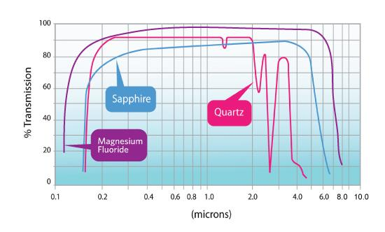
The choice is boxed in by four conditions: operating wavelength, power level, environment (humidity, temperature, pressure, corrosion) and cost. The table below puts the hard numbers of the common substrates side by side, so the impossible ones can be crossed out first.
| Material | Transmission band | Refractive index | Thermal expansion | Thermal conductivity | Typical use and limitations |
|---|---|---|---|---|---|
| K9 / BK7 | 350 nm – 2.2 μm | about 1.52 | 7.1 × 10⁻⁶/°C | about 1.1 W/(m·K) | Visible and near infrared, low power, lowest cost; contains alkali oxides and resists neither strong acids nor thermal shock |
| Fused silica | 180 nm – 2.5 μm | about 1.46 | 0.55 × 10⁻⁶/°C | about 1.4 W/(m·K) | First choice for ultraviolet to near-infrared at high power; extremely low expansion and the best thermal shock resistance, at a mid-to-high price |
| Sapphire | 150 nm – 5.5 μm | about 1.77 | about 7.5 × 10⁻⁶/°C | about 35 W/(m·K) | High pressure, high temperature and abrasive environments; second only to diamond in hardness and transparent in the infrared, but its birefringence rules it out for polarisation-sensitive paths |
| Calcium fluoride (CaF₂) | 130 nm – 9 μm | about 1.43 | 18.9 × 10⁻⁶/°C | about 9.7 W/(m·K) | Deep ultraviolet to mid-infrared with low dispersion; high expansion and poor thermal shock resistance, and it hydrolyses and fogs in long-term damp conditions |
| Zinc selenide (ZnSe) | 0.5 μm – 22 μm | about 2.4 | 7.1 × 10⁻⁶/°C | about 18 W/(m·K) | The workhorse for CO₂ lasers and thermal imaging; opaque in the visible, so alignment needs an infrared indicator or a red aiming beam |
| Germanium (Ge) | 1.8 μm – 23 μm | about 4.0 | 6.1 × 10⁻⁶/°C | about 58 W/(m·K) | Thermal imaging and CO₂ lasers; the high index gives about 36% reflection per face, so a coating is mandatory, and its properties drift strongly with temperature |
Three points are easily missed. First, the higher the refractive index the stronger the Fresnel reflection: germanium reflects about 36% per face, which makes an uncoated plate unusable and is nothing like the 4% of visible glass. Second, an order of magnitude in thermal expansion means a thermal shock that fused silica shrugs off will crack CaF₂ outright. Third, thermal conductivity decides whether the heat can escape: sapphire and germanium cope with high power density because heat leaves quickly, while BK7 can only compromise by staying at low power.
5.5 Contamination and Maintenance
The window is the first component in the system to get dirty, because it sits at the outer edge. The consequences escalate: transmission drops, scatter rises, and at high power the contamination absorbs energy, overheats locally, pits the surface and eventually fractures the plate. The process has clear positive feedback, since a dirtier window absorbs more heat and a hotter window collects the next layer of fume faster.
A protective window should therefore be designed as a consumable: mounted in a quick-change frame with a defined replacement interval, rather than dealt with after it fails. In industrial cutting and welding the interval runs from a few hours to a few hundred hours depending on material, fume load and power. Put replacement frequency and unit price into the total cost of ownership together; judging on purchase price alone tends to select the cheap plate that has to be changed every week.
Cleaning has its own rules: blow off the particles first, then drag a lint-free swab wet with solvent in one direction only, and never wipe dry, because a dry wipe presses grit into the coating and leaves permanent scratches. Once a coated window shows coating lift or pits, it is replaced, not repolished: repolishing usually costs more than a new plate.
6. Applications: Where Windows Are Fitted
Almost every application is a variant of one action: leave a path for light where something has to be kept out. What differs is only what is being kept out.
- Laser protective windows: fitted at the end of a cutting or welding head to block spatter, fume and slag and protect the focusing lens inside. It is a sacrificial part, and when it dies the rest of the path is still intact.
- Vacuum and sealed-chamber viewports: the optical path into a vacuum system, gas cell or sealed detector package. The pressure difference deflects a thin plate, so the thickness-to-diameter ratio and the resulting deflection have to be calculated.
- Spectrometer and detector windows: the cover over a sample cell or a detector chip, isolating the environment without blocking the signal band. Deep ultraviolet and infrared cases punish a poor material choice immediately.
- Infrared thermometry and thermal imaging windows: pass the infrared radiation while holding back corrosive gas and pressure. ZnSe, germanium or sapphire are usual, and in visible light such a window is an opaque dark disc.
- High-pressure and harsh-environment windows: deep-sea instruments, chemical reactors, high-pressure combustion chambers. Here mechanical strength and seal integrity matter more than the optical figures.
- Intra-cavity Brewster windows: mounted at the Brewster angle so that p-polarised light passes with zero reflection while the s-component is partly reflected, which lowers cavity loss and provides polarisation selection at the same time. It is standard in many gas lasers.
7. Common Myths: Six Widespread Misunderstandings
Windows are simple structures, yet the misconceptions cluster, because most of them grow from the intuition that a piece of glass cannot be that particular.
Myth 1: A window does not affect beam quality
Of course it does. Figure error is printed onto the transmitted wavefront at roughly (n−1), index inhomogeneity inside the material adds phase ripple, and absorption at high power creates a thermal lens. For interferometry or tight focusing, the wavefront specification of a window belongs in the same budget as the mirrors.
Myth 2: A thicker window is always stronger and better
Thickness has a price: absorption grows linearly with it, lateral displacement grows linearly with it, the extra optical path (n−1)·d grows with it, and so do weight and cost. The right approach is to calculate the minimum thickness the pressure difference and aperture demand, then add a modest safety margin rather than simply thickening the plate.
Myth 3: Any parallel plate is a window
Same shape, different job. An etalon uses its parallel faces for multiple-beam interference and is a precision wavelength-selective element; a compensator plate is there to cancel optical path; a window exists to isolate an environment. Using an etalon as a window puts a filter you did not ask for into the beam path.
Myth 4: A transparent material is all a window needs
Far from it. Bare glass in a laser path reflects 4% per face, and that return is enough to disturb a resonator; with no figure control the wavefront is dragged out of shape; with no edge preparation or sealing design the flange leaks. A usable laser window is the sum of substrate, coating, figure and seal.
Myth 5: A window is a one-off purchase
The opposite is true. Protective windows in industrial cutting and welding are standard consumables, replaced every few hours to a few hundred hours. Buying on unit price alone usually lands you on the cheap plate that needs changing weekly; add replacement frequency, downtime and labour and the conclusion often reverses.
Myth 6: An anti-reflection coating means no reflection
The coating works near its design wavelength and design angle only. A few tens of nanometres of wavelength shift, or a tilt of ten-odd degrees, and the reflectance climbs back noticeably; the coating is also the lowest damage threshold anywhere on the plate. It pushes reflection from 4% down to 0.1%, it does not make it zero.
◆ Recommended Reading
- Optical Glass and Window Materials: Principles, Classification, Parameters and 6 Common Misconceptions
- Fused Silica Glass: Principles, Properties, Classification and 6 Common Misconceptions
- Sapphire Crystals: Principles, Structure, Properties and 6 Common Misconceptions
- What Is an Optical Lens? The Focusing Element of Every Laser System
Leave a Reply