


Optical thin films are one or more layers of film deposited on the polished surface of an optical component to modify how light waves are transmitted. Depending on the application, the common functions of optical thin films fall into seven categories: reflection (HR), anti-reflection (AR), beam splitting (BS), attenuation (AT), filtering (FI), polarisation control (PBS) and phase change (PC), plus non-optical functions such as hydrophobic and conductive (ITO) coatings. This article introduces the principle, typical specifications and common materials of each function to give you a fuller picture of the field.
Contents
- 1. What Are Optical Thin Films?
- 2. Common Functions of Optical Thin Films
- A. Reflection (HR)
- B. Anti-Reflection (AR)
- C. Beam Splitting (BS)
- D. Attenuation (AT)
- E. Filtering (FI)
- F. Polarisation Control (PBS)
- G. Phase Change (PC)
- H. Non-Optical Functions
- 3. Common Misconceptions
- 4. Frequently Asked Questions (FAQ)
- 5. Conclusion
1. What Are Optical Thin Films?
In the early days, optical components made of glass were exposed to moisture, acids, alkalis and other substances in the air, which degraded their surface performance and shortened the life of optical products. To solve this problem, optical coating technology was developed: by depositing a thin film on the lens surface, the polished surface is isolated from the air, protecting the optical face.
As the technology was used, people found that a thin film could do more than protect the optical surface — it could also change the optical characteristics of a beam, for example by altering the surface transmittance or reflectance. This led to more research into coating technology. Modern optical coating refers to the process of depositing one or more thin films on the polished surface of an optical part, with the aim of modifying how light waves are transmitted — including transmission, reflection, absorption, scattering, polarisation and phase change — or of achieving some other specific purpose through the film.
2. Common Functions of Optical Thin Films
What are the common functions of optical thin films? When defining coating requirements on an optical drawing, three things normally need to be specified: first, the applicable spectral range — whether the coating is needed in the ultraviolet, visible or infrared band; second, the angle of incidence on the coating, to meet the component’s specific use in the optical system; and third, the numerical specification after coating — for example, whether reflectance must be below 0.5% or above 96%. Depending on the application, the common functions of optical thin films can be grouped into seven categories (plus one class of non-optical functions), summarised below:
| Function | Abbreviation | Brief role | Typical specifications and applications |
|---|---|---|---|
| Reflection | HR (High Reflection) | Raises the reflectance of an optical surface so it can serve as a mirror | Metal films up to about 97%, dielectric films up to 99.99%; used for mirrors, cavity mirrors, etc |
| Anti-reflection | AR (Anti-Reflection) | Lowers surface reflectance and increases beam transmission | Multilayer films in the visible band can reach reflectance below 0.5%; used for lenses, windows, displays, etc |
| Beam splitting | BS (Beam Splitting) | Splits an incident beam into transmitted and reflected beams at a set ratio | Common ratios 1:1, 1:2, etc.; used in interferometers, laser systems, etc |
| Attenuation | AT (Attenuating) | Weakens the transmitted beam by absorption | Constant and graded attenuators; used in sunglasses, optical instruments, etc |
| Filtering | FI (Filtering) | Passes only light in a chosen spectral band and rejects the rest | Bandpass, short-pass and long-pass filters; used in spectrometers, photography, etc |
| Polarisation control | PBS (Polarizing Beam Splitter) | Controls beam polarisation and separates p- and s-polarised light | Polarisers, polarising beam-splitter cubes; used in 3D cinema glasses, LCD displays, laser systems, etc |
| Phase change | PC (Phase Change) | Controls the phase of light in different polarisation states | Phase matching, phase retardation; used in ultrafast optics, interferometry, etc |
| Non-optical function | — | Surface functions such as hydrophobic and conductive | Hydrophobic films, ITO conductive films; used for waterproof lenses, touchscreens, solar cells, etc |
A. Reflection (HR Coating)
A film with this function is called a reflective coating, often referred to as a high-reflection film (HR film). It increases the reflectance of an optical surface; once coated, the surface can be used as a mirror.
Different reflectance targets call for different film designs. Common reflective coatings fall broadly into two types. One is metal films, such as aluminium, silver and gold — these are usually thin and preserve surface figure well, with reflectance reaching up to about 97%. The other is dielectric films, built by stacking different dielectric materials into a multilayer — for example, a dielectric reflective film made from magnesium fluoride (MgF2) and tantalum pentoxide (Ta2O5) can reach a reflectance of 99.99%. Dielectric films are generally thicker, however, and so are less able to maintain high-precision surface figure. As an example, the figure below shows reflectance curves for BK7 coated with gold, silver, aluminium and dielectric films in the visible band:
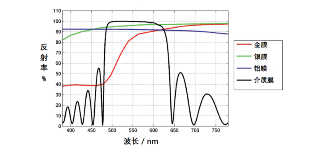
In the figure above, the beam is at 0° incidence. The red line is the gold film, green the silver film, blue the aluminium film and black the dielectric film. The dielectric film is made of 10 layers of MgF2 and 11 layers of Ta2O5, with a total MgF2 thickness of 66 nm and a total Ta2O5 thickness of 99 nm; its reflectance is the highest of all the designs shown.
B. Anti-Reflection (AR Coating)
A film with this function is called an anti-reflection film or AR film; its role is to lower the reflectance of an optical surface over a given spectral range, thereby increasing the beam’s transmission through the component. Anti-reflection films are usually built from one or more layers of different dielectric materials — magnesium fluoride and tantalum pentoxide can be used here too. The figure below shows surface reflectance curves for BK7 in the visible band when uncoated, coated with a single dielectric layer and coated with a multilayer dielectric stack:
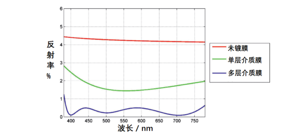
In the figure above, the beam is at 0° incidence. The red line is the uncoated polished BK7 surface, with reflectance of about 4.2%; the green line is the reflectance curve for a single MgF2 layer about 99 nm thick deposited on the substrate, where reflectance is visibly reduced; the blue line is a multilayer dielectric stack of three MgF2 and three Ta2O5 layers on the substrate, where surface reflectance is already below 0.5%.
Coating materials are not limited to MgF2 and Ta2O5. Many materials are available in practice, mainly fluorides, oxides and other compounds: common fluorides also include lanthanum fluoride (LaF3), yttrium fluoride (YF3) and ytterbium fluoride (YbF3); common oxides also include silicon dioxide (SiO2), titanium dioxide (TiO2), zirconium dioxide (ZrO2) and hafnium dioxide (HfO2); and there are compounds such as zinc sulfide (ZnS) and zinc selenide (ZnSe).
C. Beam Splitting (Beam Splitting)
By depositing a coating, a beam incident on the coated surface can be split into two: one transmitted through and one reflected, with the intensity ratio of the two defined during film design. The most common is a 1:1 beam-splitter film, where the transmitted and reflected intensities are equal; in practice, 1:2 and many other ratios are also used.
D. Attenuation (Attenuating)
Coating a flat plate can weaken the intensity of the beam passing through it, with the lost light absorbed by the film rather than reflected back, achieving beam attenuation. The sunglasses people wear every day absorb ultraviolet light and reduce light intensity, protecting the eyes. In optical instruments there are attenuators with constant attenuation, where every point of the product attenuates the incident beam to the same degree, and attenuators with graded attenuation — as the graded attenuator is rotated through a full turn about its centre, the transmitted intensity changes continuously from strong to weak.
E. Filtering (Filtering)
The component used for filtering is usually called an optical filter; it passes light in a chosen spectral band and rejects light in bands of no interest. Filters are widely used in optical instruments and, classified by spectral characteristic, include bandpass, short-pass and long-pass filters. In photography, filters are often used as colour selectors to obtain photographs with a particular artistic effect.
F. Polarisation Control (Polarizing Control)
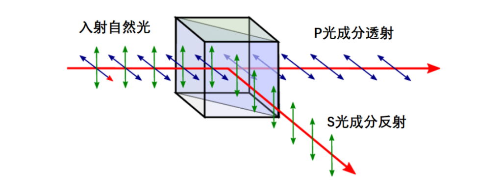
As we know, linearly polarised light splits into p- and s-polarised light, whose vibration directions are perpendicular to each other and whose propagation is independent. Through coating, the polarisation state of an incident beam can be controlled. A common application is the polariser, which turns natural light into polarised light and is widely used in 3D cinema glasses and LCD displays. The polarising beam-splitter cube (PBS) commonly used in optical instruments is made by depositing a polarising film on the hypotenuse of a cemented right-angle prism, splitting the incident beam into p-light (transmitted) and s-light (reflected) at 90° to each other, thereby acting as a polariser. The PBS principle is shown below:
G. Phase Change (Phase Change)
As mentioned above, optical thin films are usually a stack of one or more dielectric layers. When a beam is reflected or refracted at the interfaces between different media, the phase of light in different polarisation states changes. Making use of this property, optical thin films can control the phase of the p- and s-components of incident light, in applications such as phase matching and phase retardation.
H. Non-Optical Functions
There is another class of optical thin films that has no optical function but is nevertheless needed in practice. For example, when an optical surface must be waterproofed, a hydrophobic film is deposited — this makes water droplets less likely to cling to the lens, so they run off efficiently like droplets on a lotus leaf. In other cases the optical surface must conduct electricity, and an ITO (Indium Tin Oxide) film is deposited; this film has good transmittance in the visible band and excellent conductivity, providing transparent conduction for flat-panel displays, touchscreens, solar cells and other electronic products.
3. Common Misconceptions
There are a few commonly confused ideas about optical thin films that are worth noting when selecting and using them:
Misconception 1: The higher the reflectance, the better.
In fact, coating specifications must match the application: mirrors aim for high reflectance, while lenses and windows should minimise it (anti-reflection); and higher reflectance usually means a narrower bandwidth, greater sensitivity to incidence angle and a higher cost, so it is not suitable in every situation.
Misconception 2: Ignoring angle of incidence and spectral range.
The reflectance and transmittance specifications of a film are usually designed for a particular incidence angle (such as 0° normal incidence or 45° oblique incidence) and a particular spectral range; in use, deviating from the design conditions shifts the specifications noticeably.
Misconception 3: Metal films are obsolete and dielectric films should be used everywhere.
In fact, metal films have a broad bandwidth, are insensitive to angle and are low-cost, remaining the mainstream choice for broadband reflection and cost-sensitive applications; dielectric films offer higher reflectance (up to 99.99%) and lower absorption, but with narrower bandwidth, angle sensitivity and higher cost. Each has its place.
Misconception 4: Coated components can be wiped and cleaned freely.
Compared with bare glass, a film is more delicate: high-power laser light, humidity or acid–alkali environments accelerate its ageing and damage; when cleaning, avoid dry or hard wiping and use the specified tools and solvents.
4. Frequently Asked Questions (FAQ)
What are the common functions of optical thin films?
There are seven main categories: reflection (HR, high-reflection film), anti-reflection (AR, AR/anti-reflection film), beam splitting (BS, beam-splitter film), attenuation (AT, attenuator), filtering (FI, filter), polarisation control (PBS, polarisers and polarising beam-splitter cubes) and phase change (PC). There are also non-optical functions such as hydrophobic films and ITO transparent conductive films.
What is the difference between an HR film and an AR film?
The two work in opposite directions. HR (High Reflection) is a high-reflection film, used to make the reflectance of an optical surface as high as possible: metal films reach about 97% and dielectric films up to 99.99%, with typical applications in mirrors and laser cavity mirrors. AR (Anti-Reflection) is an anti-reflection film (also called an AR coating), used to make surface reflectance as low as possible: multilayer anti-reflection films in the visible band can be below 0.5%, increasing transmittance, with typical applications in lenses, windows and displays.
What are the characteristics of metal and dielectric films, and how do you choose?
Metal films (aluminium, silver, gold, etc.) reflect over a broad band, are insensitive to incidence angle, use mature processes and are low-cost, with reflectance generally up to about 97%, but they have absorption losses and suit broadband reflection and cost-sensitive applications. Dielectric films are built from alternating high- and low-refractive-index layers, achieving reflectance of 99.99% with very low absorption, but they are thicker, narrower in bandwidth, angle-sensitive and more costly, suiting laser systems and other applications with demanding requirements on reflectance and loss.
What is a PBS and what is it used for?
A PBS is a polarising beam-splitter cube: a polarising beam-splitter film is deposited on the hypotenuse of a cemented right-angle prism, splitting the incident light into p-light (transmitted) and s-light (reflected), which emerge at 90° with mutually perpendicular vibration directions. PBSs are widely used in laser systems, optical isolators, optical measurement and display equipment for polarising, analysing and polarisation splitting.
What coating materials are commonly used?
Common coating materials include low-index materials such as magnesium fluoride (MgF2), lanthanum fluoride (LaF3), yttrium fluoride (YF3), ytterbium fluoride (YbF3) and silicon dioxide (SiO2); and high-index materials such as tantalum pentoxide (Ta2O5), titanium dioxide (TiO2), zirconium dioxide (ZrO2) and hafnium dioxide (HfO2). There are also compounds such as zinc sulfide (ZnS) and zinc selenide (ZnSe), and metal coating materials such as aluminium, silver and gold. The specific combination is chosen according to the spectral range, specification requirements and damage threshold.
5. Conclusion
Depending on the film design, optical thin films commonly provide high reflection, anti-reflection, beam splitting, attenuation, filtering, polarisation control and beam phase change; there are also non-optical functions such as hydrophobic films and ITO films, which are frequently used in practice. If you would like to learn more about any of these functions, please browse the optical coating articles in the Laser Encyclopedia section, or contact us to discuss.
Leave a Reply